Introduction to Circuit Protection
Introduction to Circuit Protection
Introduction to Circuit Protection

Create successful ePaper yourself
Turn your PDF publications into a flip-book with our unique Google optimized e-Paper software.
<strong>Introduction</strong> <strong>to</strong> <strong>Circuit</strong> <strong>Protection</strong><br />
Transien<strong>to</strong>logy<br />
Overvoltage Suppression Facts<br />
Transient Voltage Scenarios<br />
ESD (Electrostatic Discharge)<br />
Electrostatic discharge is characterized by very fast rise times and very<br />
high peak voltages and currents. This energy is the result of an imbalance<br />
of positive and negative charges between objects.<br />
Below are some examples of the voltages which can be generated,<br />
depending on the relative humidity (RH):<br />
• Walking across a carpet:<br />
35kV @ RH = 20%; 1.5kV @ RH = 65%<br />
• Walking across a vinyl floor:<br />
12kV @ RH = 20%; 250V @ RH = 65%<br />
• Worker at a bench:<br />
6kV @ RH = 20%; 100V @ RH = 65%<br />
• Vinyl envelopes:<br />
7kV @ RH = 20%; 600V @ RH = 65%<br />
• Poly bag picked up from desk:<br />
20kV @ RH = 20%; 1.2kV @ RH = 65%<br />
Referring <strong>to</strong> Table 2 on the previous page, it can be seen that ESD that is<br />
generated by everyday activities can far surpass the vulnerability threshold<br />
of standard semiconduc<strong>to</strong>r technologies. Figure 2 shows the ESD<br />
waveform as defined in the IEC 61000-4-2 test specification.<br />
Inductive Load Switching<br />
The switching of inductive loads generates high energy transients which<br />
increase in magnitude with increasingly heavy loads. When the inductive<br />
load is switched off, the collapsing magnetic field is converted in<strong>to</strong> electrical<br />
energy which takes the form of a double exponential transient.<br />
Depending on the source, these transients can be as large as hundreds<br />
of volts and hundreds of Amps, with duration times of 400 milliseconds.<br />
Typical sources of inductive transients are:<br />
• Genera<strong>to</strong>r<br />
• Mo<strong>to</strong>r<br />
• Relay<br />
• Transformer<br />
These examples are extremely common in electrical and electronic systems.<br />
Because the sizes of the loads vary according <strong>to</strong> the application,<br />
the wave shape, duration, peak current and peak voltage are all variables<br />
which exist in real world transients. Once these variables can be approximated,<br />
a suitable suppressor technology can be selected.<br />
12<br />
V S<br />
www.littelfuse.com<br />
V<br />
90%<br />
10%<br />
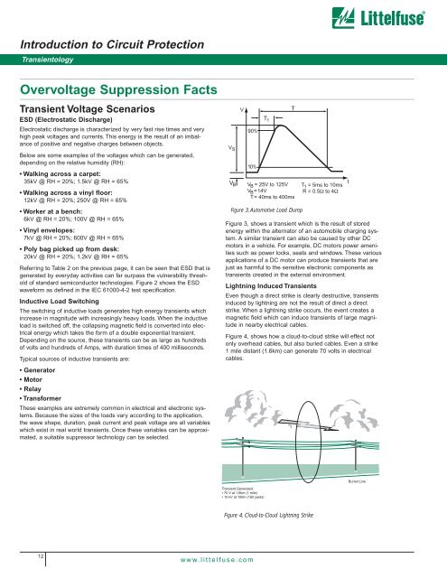
Figure 3, shows a transient which is the result of s<strong>to</strong>red<br />
energy within the alterna<strong>to</strong>r of an au<strong>to</strong>mobile charging system.<br />
A similar transient can also be caused by other DC<br />
mo<strong>to</strong>rs in a vehicle. For example, DC mo<strong>to</strong>rs power amenities<br />
such as power locks, seats and windows. These various<br />
applications of a DC mo<strong>to</strong>r can produce transients that are<br />
just as harmful <strong>to</strong> the sensitive electronic components as<br />
transients created in the external environment.<br />
Lightning Induced Transients<br />
Even though a direct strike is clearly destructive, transients<br />
induced by lightning are not the result of direct a direct<br />
strike. When a lightning strike occurs, the event creates a<br />
magnetic field which can induce transients of large magnitude<br />
in nearby electrical cables.<br />
Figure 4, shows how a cloud-<strong>to</strong>-cloud strike will effect not<br />
only overhead cables, but also buried cables. Even a strike<br />
1 mile distant (1.6km) can generate 70 volts in electrical<br />
cables.<br />
Transient Generated:<br />
• 70 V at 1.6km (1 mile)<br />
• 10 kV at 150m (160 yards)<br />
T 1<br />
Figure 4. Cloud-<strong>to</strong>-Cloud Lightning Strike<br />
T<br />
V B VB = 25V <strong>to</strong> 125V<br />
V B = 14V<br />
T= 40ms <strong>to</strong> 400ms<br />
Figure 3. Au<strong>to</strong>motive Load Dump<br />
T 1 = 5ms <strong>to</strong> 10ms<br />
R = 0.5Ω <strong>to</strong> 4Ω<br />
t<br />
Buried Line