GEMINI Laser Marking System - Telesis Technologies, Inc.
GEMINI Laser Marking System - Telesis Technologies, Inc.
GEMINI Laser Marking System - Telesis Technologies, Inc.

You also want an ePaper? Increase the reach of your titles
YUMPU automatically turns print PDFs into web optimized ePapers that Google loves.
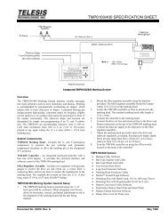
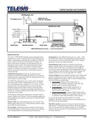
<strong>System</strong> Setup<br />
Complete installation procedures are provided in the <strong>GEMINI</strong><br />
Installation/Maintenance Manual. The following procedures are<br />
listed for reference only to provide a general overview of the<br />
installation process.<br />
1. Equipment should remain powered down and in the OFF<br />
position until the mounting is complete.<br />
2. Place the computer, monitor, keyboard, and laser controller<br />
in the desired location. The standard fiber optic cable length<br />
is 3 meters (9.8 feet) long between the laser marking head<br />
assembly and the controller.<br />
3. Locate the laser marking head assembly on the selected<br />
mounting.<br />
a. Do not to bend or kink the fiber optic cable. The<br />
fiber optic cable will tolerate approximately 305 mm<br />
(12 in.) diameter bend without damage.<br />
b. Allow a minimum distance of 150 mm (6 in.) at the<br />
rear of the laser. This will provide sufficient room<br />
for a proper bend radius of the fiber optic cable.<br />
4. Mount the laser marking head assembly using any four of<br />
the six factory-tapped M5-0.8 mounting holes provided.<br />
a. Locate the six pre-drilled M5-0.8 mounting holes.<br />
Refer to the Mounting and Dimension Details drawing<br />
more information.<br />
b. <strong>Telesis</strong> recommends using a minimum of three (3)<br />
attach points for mounting the <strong>GEMINI</strong> laser.<br />
c. Mounting bolts must not extend into the marking<br />
head more than 7.6 mm (.3 in) to avoid interference<br />
with the internal components.<br />
5. Secure the laser to the mounting fixture using M5-0.8 bolts<br />
and lock washers. Do not over tighten bolts.<br />
6. Ensure the laser control console power switch (on the front<br />
panel) is OFF.<br />
7. Select the proper voltage setting (either 115V or 230V), and<br />
then connect the power cable.<br />
8. Refer to the <strong>GEMINI</strong> Operation Supplement for proper<br />
startup procedure of the complete system.<br />
9. Refer to the laser marking system Operation Manual for<br />
complete information on using the system software.<br />
<strong>GEMINI</strong> <strong>Laser</strong> <strong>Marking</strong> <strong>System</strong><br />
General Mounting Procedures<br />
If you chose to integrate the laser into a workstation that has not<br />
been designed by <strong>Telesis</strong>, you should keep in mind the following<br />
engineering considerations when integrating your system.<br />
• Design simple X-, Y-, and Z-axis adjustments.<br />
When designing a mounting fixture for the laser marking<br />
head, allow for simple three-axis adjustment to aid in<br />
horizontal, vertical, and lateral alignment of the laser marking<br />
head. Experience has shown that a minimum adjustment<br />
value of 12.7 mm (0.50 in.) is a prudent design consideration<br />
if the intent is to integrate the laser into workstation not<br />
designed by <strong>Telesis</strong>.<br />
• Ensure the part and the part holding fixture are<br />
perpendicular to the final objective lenses.<br />
When designing a work piece holding fixture, ensure the<br />
fixture is flat relative to the final objective lens of the galvo<br />
block assembly and square to the centerline of the laser<br />
marking field.<br />
• Ensure the part is stable and will not move during<br />
marking.<br />
<strong>Laser</strong> marking is a non-contact marking method. Typically all<br />
that is needed is simple fixturing pockets or X-axis, Y-axis<br />
datum rails.<br />
• Ensure the part width and length will fit in the<br />
marking area.<br />
Double check that all the parts to be marked will fit within<br />
the laser marking field. Ensure the marking area is not<br />
obstructed and can be targeted by the laser beam.<br />
• Ensure the combined total height of the part and<br />
fixturing does not exceed the working clearance of<br />
the final objective lens selected.<br />
Care should be taken to ensure that the laser beam can be<br />
focused on the part. The total combination of the part and<br />
fixturing height must not exceed the adjustment capability of<br />
the customer-supplied Z-axis. The working clearance is the<br />
distance between the bottom of the lens and the top of the part to<br />
be marked. See <strong>Marking</strong> Characteristics (<strong>Marking</strong> Field Size)<br />
for details on working clearances for the available lenses.<br />
Doc. No. 6 of 6