DI Series Shunt Isolator - LEM
DI Series Shunt Isolator - LEM
DI Series Shunt Isolator - LEM

You also want an ePaper? Increase the reach of your titles
YUMPU automatically turns print PDFs into web optimized ePapers that Google loves.
ITC series Current Transducers: Main Characteristics<br />
ITC series reaches the Class 0.5R measurement accuracy<br />
according to Pr EN 50463.<br />
Linearity error is less than 0.05% of peak current, offset<br />
currents less than +/- 20 µA are really stable, and offset drift in<br />
temperature is less than 100 µA. ITC models provide a current<br />
output thanks to the Class D amplifier.<br />
With the use of the double Class D output current generator,<br />
the supply currents are balanced and reduced versus a<br />
transducer using a Class AB amplifier.<br />
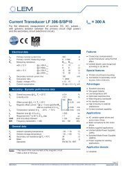
The supply current is always positive and almost equal on<br />
both supplies: 0.3 A at nominal output current on each power<br />
supply polarity (Fig. 12), electronic losses are less than 6 W<br />
when supplied under +/- 24 V.<br />
For instance, using a Class AB amplifier would have required a<br />
supply current of 1.6 A and would have created 30 W of losses<br />
at nominal current.<br />
Fig. 12. Consumption currents on each power supply polarity<br />
in regards with the primary current (R M = 0.1 Ω, ± V C = ± 24 V)<br />
(both supply currents are identical)<br />
Use of large heatsink is not anymore necessary due to this<br />
losses reduction leading to current transducer largely reduced<br />
in size.<br />
With less current consumption needed, power supplies to<br />
be associated with the ITC transducers can be of a lower<br />
capacity and then cheaper.<br />
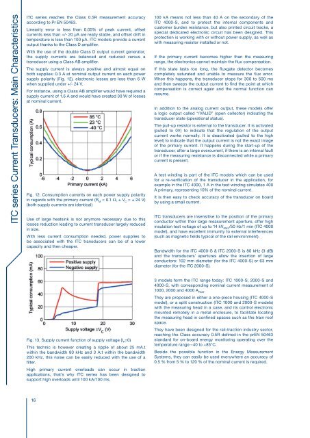
Fig. 13. Supply current function of supply voltage (I P =0)<br />
This technic is however creating a ripple of about 25 mA.t<br />
within the bandwidth 80 kHz and 3 A.t within the bandwidth<br />
200 kHz, this noise can be easily reduced with the use of a<br />
filter.<br />
High primary current overloads can occur in traction<br />
applications, that’s why ITC series has been designed to<br />
support high overloads until 100 kA/100 ms.<br />
16<br />
100 kA means not less than 40 A on the secondary of the<br />
ITC 4000-S, and to protect the internal components and<br />
customer burden resistance, but also printed circuit tracks, a<br />
special dedicated electronic circuit has been designed. This<br />
protection is working with or without power supply, as well as<br />
with measuring resistor installed or not.<br />
If the primary current becomes higher than the measuring<br />
range, the electronics cannot maintain the flux compensation.<br />
If this state lasts too long, the fluxgate detector becomes<br />
completely saturated and unable to measure the flux error.<br />
When this happens, the transducer stops for 300 to 500 ms<br />
and then sweeps the output current to find the point at which<br />
compensation is correct again and the normal function can<br />
resume.<br />
In addition to the analog current output, these models offer<br />
a logic output called “/VALID” (open collector) indicating the<br />
transducer state (operational status).<br />
The pull-up resistor is external to the transducer. It is activated<br />
(pulled to 0V) to indicate that the regulation of the output<br />
current works normally. It is deactivated (pulled to the high<br />
level) to indicate that the output current is not the exact image<br />
of the primary current. It happens during the start-up of the<br />
transducer, after a large overcurrent, if there is an internal fault<br />
or if the measuring resistance is disconnected while a primary<br />
current is present.<br />
A test winding is part of the ITC models which can be used<br />
for a re-verification of the transducer in the application, for<br />
example in the ITC 4000, 1 A in the test winding simulates 400<br />
A primary, representing 10% of the nominal current.<br />
It is then easy to check accuracy of the transducer on board<br />
by using a small current.<br />
ITC transducers are insensitive to the position of the primary<br />
conductor within their large measurement aperture, offer high<br />
insulation test voltage of up to 14 kV RMS /50 Hz/1 min (ITC 4000<br />
model), and have excellent immunity to external interferences<br />
(such as magnetic fields typical of the rail environment).<br />
Bandwidth for the ITC 4000-S & ITC 2000-S is 80 kHz (3 dB)<br />
and the transducers’ apertures allow the insertion of large<br />
conductors: 102 mm diameter (for the ITC 4000-S) or 63 mm<br />
diameter (for the ITC 2000-S).<br />
3 models form the ITC range today: ITC 1000-S, 2000-S and<br />
4000-S, with corresponding nominal current measurement of<br />
1000, 2000 and 4000 A RMS .<br />
They are proposed in either a one-piece housing (ITC 4000-S<br />
model), or a split construction (ITC 1000 and 2000-S models)<br />
with the measuring head in a case, and its control electronic<br />
mounted remotely in a metal enclosure, to facilitate locating<br />
the measuring head in confined spaces such as the train roof<br />
space.<br />
They have been designed for the rail-traction industry sector,<br />
reaching the Class accuracy 0.5R defined in the prEN 50463<br />
standard for on-board energy monitoring operating over the<br />
temperature range –40 to +85°C.<br />
Beside the possible function in the Energy Measurement<br />
Systems, they can easily be used everywhere an accuracy of<br />
0.5 % from 5 % to 120 % of the nominal current is required.