DI Series Shunt Isolator - LEM
DI Series Shunt Isolator - LEM
DI Series Shunt Isolator - LEM

Create successful ePaper yourself
Turn your PDF publications into a flip-book with our unique Google optimized e-Paper software.
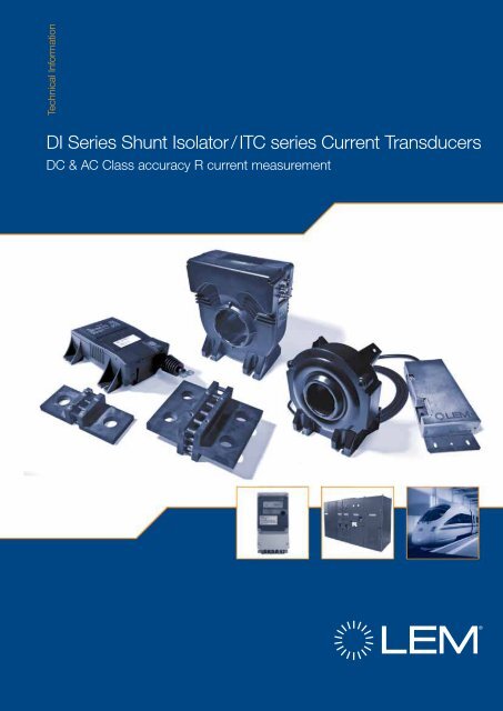
Technical Information<br />
<strong>DI</strong> <strong>Series</strong> <strong>Shunt</strong> <strong>Isolator</strong> / ITC series Current Transducers<br />
DC & AC Class accuracy R current measurement
DC & AC Class accuracy R Current Measurement<br />
<strong>DI</strong> series <strong>Shunt</strong> <strong>Isolator</strong><br />
ITC series Current Transducers<br />
Measure DC and AC currents with a Class accuracy R (Railway)<br />
Market regulations require improvements for Railway<br />
Energy Billing.<br />
• European rail freight markets are liberalized (privatization<br />
of the rail networks into infrastructure and operators)<br />
• Since the beginning of January 2010 passenger rail<br />
markets are opened to cross-border competition<br />
Liberalization of European railway markets leads to:<br />
• new competitors in each national market<br />
• increasing cross-border traffic<br />
• new situation concerning intra- und inter-modal<br />
competition<br />
• rising demands in terms of cost transparency (exact<br />
electricity consumption must be invoiced)<br />
Traction Units consume energy in different countries along<br />
their way:<br />
• Railway Undertaking (RU) have contractual relationships<br />
with the respective Infrastructure Manager (IM)<br />
• In order to be able to transparently bill the energy<br />
consumption, the RU will need information regarding<br />
each border crossing<br />
• The IM has to invoice the RU for the supply of energy<br />
The on-board Energy Measuring System (EMS) is the<br />
system for measurement of electric energy taken from or<br />
returned (during regenerative braking) to the overhead<br />
contact line (OCL) by the traction unit, supplied from the<br />
external electric traction system.<br />
This energy measurement allows the operators to better<br />
understand their real consumption and will enable energy<br />
management to reduce energy consumption for example.<br />
The Energy Measurement Function (EMF), includes voltage<br />
and current measurement.<br />
The new EN 50463 standard defines characteristics<br />
of transducers for current and voltage DC or AC<br />
measurement as well as the energy measurement function.<br />
2<br />
In order to fulfill this standard, <strong>LEM</strong> proposes different<br />
solutions for current and voltage measurements:<br />
• DV family for DC voltage measurement Class 0.5R for a<br />
single network voltage<br />
• <strong>DI</strong> family (to be used with a shunt Class 0.2) for DC<br />
current measurement Class 1R<br />
• ITC family for DC current measurement Class 0.5R<br />
Common features:<br />
• Measurement of all types of signals: DC, AC, pulsed and<br />
complex<br />
• Compact size<br />
• High galvanic insulation between primary (high power)<br />
and secondary circuits (electronic circuit)<br />
• Low consumption technology<br />
• Excellent accuracy to suit to high demanding<br />
applications such as energy metering<br />
• Low temperature drift of accuracy<br />
• High insulation and partial discharge levels in order to<br />
guarantee safety<br />
• Good immunity against external electric, magnetic and<br />
electromagnetic fields for EMC protection<br />
• Low level of emission<br />
• Compliant to fire and smoke, mandatory in railway<br />
applications<br />
• Low influence of common mode voltage<br />
• Fast response time<br />
• Large bandwidth<br />
• Low noise<br />
• Modular approach allows easy adaptation with various<br />
connections available for the secondary side like<br />
connectors, shielded cables, terminals (threaded studs,<br />
M4, M5, UNC ect) according to customer specifications<br />
• Reliability and lifetime are guaranteed by the quality in<br />
design and process and ageing tests
The Energy Measurement Function must have a total<br />
accuracy of 1,5 % for AC and 2 % for DC at + 25°C.<br />
The accuracy of current transducer, voltage<br />
transducer and Energy Meter is measured<br />
separately and combined for the overall accuracy<br />
using the following formula:<br />
2 2 2<br />
ε = ε + ε + ε EMF VMF CMF ECF<br />
With e EMF = Overall accuracy of EMF (system of current sensor, voltage sensor and energy meter)<br />
e VMF = Class accuracy of Voltage Measurement Function (Voltage transducer)<br />
e CMF = Class accuracy of Current Measurement Function (Current transducer)<br />
e ECF = Class accuracy of Energy Calculation Function (Energy meter)<br />
The EN 50463 gives the following details for the measurement of DC currents:<br />
Accuracy class<br />
Percentage error limits — DC current transducers<br />
± Maximum percentage current (ratio) error at percentage of rated<br />
primary current (I PN) shown below, DC transducers<br />
Temperature condition: 23°C+/-2°C<br />
1 % 5 % 10 % 20 % 100 % 120 %<br />
0,2 R 2 0,4 0,2 0,2 0,2 0,2<br />
0,5 R 5 1 0,5 0,5 0,5 0,5<br />
0,75 R 7,5 1,5 0,75 0,75 0,75 0,75<br />
1 R 10 2 1 1 1 1<br />
For AC current transducers, the maximum permissible error at 1% of I PN is 5% (Class 1R)!<br />
Value of current System<br />
type<br />
Influence quantities for current transducers<br />
Transducer temperature coefficient [%/K]<br />
Ambient temperature variation (main<br />
range)<br />
-10 °C to +60 °C*<br />
Ambient temperature variation<br />
(extended range)<br />
-40 °C to –10 °C* and<br />
+60 °C to +75 °C*<br />
0,1I PN ≤ I ≤ 1,2I PN DC 0,01 0,02<br />
0,05I PN ≤ I ≤ 0,1I PN DC 0,02 0,04<br />
0,01I PN ≤ I ≤ 0,05I PN DC 0,1 0,2<br />
*Note: reference temperature is at +/-2%<br />
3<br />
DC & AC Class accuracy R Current Measurement
Standards<br />
4<br />
Energy measurement<br />
EN 50463<br />
These transducers comply to the EN 50463<br />
standard for energy measurement:<br />
• DV family for DC voltage measurement Class 0.5R<br />
for a single network voltage<br />
• <strong>DI</strong> family (to be used with 1 shunt Class 0.2) for<br />
DC current measurement Class 1R<br />
• ITC family for DC current measurement Class 0.5R<br />
It is possible to use these transducers for bi voltage<br />
applications (when switching from a network to<br />
another one when crossing) with a slightly derated<br />
accuracy.<br />
These transducers have a very low sensitivity to<br />
external magnetic DC or AC fields.<br />
Traction standard<br />
EN 50155<br />
The EN 50155 standard dedicated to “Electronic<br />
Equipment used on Rolling stock” in railway<br />
applications is our standard of reference for<br />
electrical, environmental and mechanical<br />
parameters.<br />
It guarantees the overall performances of our<br />
products in railway environments.<br />
Fire and smoke<br />
NFF 16101/102<br />
Materials used for the DV, <strong>DI</strong>, ITC products comply<br />
with the NFF 16101/2 standards for fire and smoke<br />
classification (tests report for materials available on<br />
request).<br />
EMC<br />
EN 50121-3-2<br />
These transducers comply to the EN 50121-<br />
3-2 standard for emission and susceptibility<br />
(railway EMC standard) in its latest update,<br />
with EMC constraints higher than those of the<br />
typical industrial application standards.<br />
CE Marking 2004/108/EEC &<br />
Low voltage directive<br />
The DV, <strong>DI</strong>, ITC products are CE marked as a<br />
guarantee of the product compliance to the<br />
European EMC directive 2004/108/EEC and low<br />
voltage directive. They also comply with the derived<br />
local EMC regulations (EMC: Electro-Magnetic<br />
Compatibility).<br />
Insulation and safety<br />
EN 50124-1<br />
The EN 50124-1 (“Basic requirements – clearances<br />
and creepage distances for all electrical and<br />
electronic equipment”) standard has been used as<br />
a reference to design the creepage and clearance<br />
distances for t he DV, <strong>DI</strong>, ITC products.<br />
IRIS<br />
Our main production centers for traction<br />
transducers are IRIS certified.<br />
ISO 14000<br />
<strong>LEM</strong> is proud to be able to contribute to<br />
energy savings and is certified ISO 14001 for<br />
environmental management standards.
<strong>DI</strong> series solution (<strong>Shunt</strong> <strong>Isolator</strong>)<br />
The <strong>DI</strong> shunt isolator series allows an insulated<br />
measurement of a voltage across a shunt from<br />
30 mV up to 200 mV RMS providing high voltage<br />
insulation. <strong>DI</strong> product is available for Traction and<br />
Industry applications.<br />
The <strong>DI</strong> (based on the DV product technology)<br />
is used to measure the voltage across a shunt<br />
in vehicles that are supplied with energy from<br />
networks up to 3000 V. The transmission of power<br />
and signals from a high voltage environment<br />
to a low voltage environment requires specific<br />
insulation features depending on the application.<br />
The <strong>DI</strong> fulfils all the required standards to enable<br />
these features.<br />
To operate, <strong>DI</strong> only needs to be connected to a<br />
shunt, and to a standard DC power supply in the<br />
range of +/- 13.5 to +/- 26.4 V.<br />
The <strong>DI</strong> models have been specially designed for<br />
the railway environment and to respond to the<br />
technology evolution in converters used in trains<br />
and locomotives as well as in stationary facilities<br />
like substations in DC switchgear, rectifiers<br />
requiring better performances such as:<br />
• Class 1R according EN 50463<br />
(including a shunt class 0.2).<br />
It can easily be associated to a <strong>Shunt</strong> already part<br />
of one installation where isolation is required.<br />
The cable connection from <strong>Shunt</strong> to the <strong>DI</strong> must<br />
be twisted (recommended wire 1.5 mm2). Secondary cable connections for the <strong>DI</strong> must be<br />
with a shield.<br />
High Isolation<br />
Class 1R accuracy<br />
5<br />
<strong>DI</strong> series (<strong>Shunt</strong> <strong>Isolator</strong>): Main Characteristics
<strong>DI</strong> series Technology<br />
<strong>Shunt</strong><br />
<strong>DI</strong> series: Insulating Digital Technology<br />
The measuring voltage across a shunt (image of the primary current) is applied directly to the <strong>DI</strong> primary<br />
connections, the analogue signal is converted to a serial digital signal using a Sigma-Delta modulator.<br />
This digital signal is then transmitted to the secondary side over an insulating transformer ensuring the<br />
insulation between the high voltage side (called “primary”) and the low voltage side (called “secondary“).<br />
The signal is reshaped on the secondary side of the transformer, then decoded and filtered through a<br />
digital filter to feed a micro-controller using a Digital/Analogue (D/A) converter.<br />
The analogue voltage signal at the output of the micro-controller and D/A converter is then transformed<br />
through a voltage/current converter protected against short circuits.<br />
The recovered output signal is completely insulated against the primary (high voltage), and is an exact<br />
representation of the primary current.<br />
A DC/DC converter connected to customer power supply provides different supply voltages for the<br />
secondary side of the transducer, primary side being supplied through another insulated transformer<br />
based on the same principle than the one used for the data transmission.<br />
Primary<br />
Current<br />
6<br />
I P<br />
+In<br />
-In<br />
-Up<br />
Rectifier<br />
Filter<br />
+Up -Up 0V +5V<br />
Modulator<br />
Supply<br />
Bitstream<br />
Power<br />
Supply<br />
Digital<br />
Filter<br />
Insulating digital technology features<br />
• Measurement of all types of signals: DC, AC,<br />
pulsed and complex<br />
• Low volume technology: compact size<br />
• High galvanic insulation between primary (high power)<br />
and secondary circuits (electronic circuit)<br />
• Low consumption technology<br />
• Very high accuracy<br />
• Low temperature drift<br />
Micro controller<br />
D/A Converter<br />
U / I<br />
Generator<br />
+V C<br />
-V C<br />
Output<br />
R M
<strong>DI</strong> <strong>Series</strong> (<strong>Shunt</strong> <strong>Isolator</strong>): Main Characteristics<br />
Absolute maximum ratings<br />
Maximum supply voltage for current output <strong>DI</strong>s<br />
(terminal +V C to -V C , no input voltage, 0.1 s)<br />
Parameter Symbol Value<br />
Maximum supply voltage (working) (-40..85°C) ± V C ±26.4 V<br />
Maximum input voltage (1.2/50µs exponential shape) 30 kV<br />
Maximum input voltage (DC) (-40..85°C) V PM<br />
Maximum steady state input voltage (-40..85°C) V PN<br />
Absolute maximum ratings apply at 25°C unless otherwise noted.<br />
Stresses above these ratings may cause permanent damage.<br />
This is a stress rating only; functional operation of the device at these or any other conditions above<br />
those indicated in the operational section of this data sheet are not implied.<br />
Exposure to absolute maximum ratings for extended periods may degrade reliability.<br />
Insulation characteristics<br />
68 V<br />
Parameter Symbol Unit Min Comment<br />
RMS voltage for AC insulation<br />
test 50/60 Hz /1 min<br />
RMS voltage for partial discharge<br />
extinction @ 10 pC<br />
V d kV 18.5 100% tested<br />
V e V 5<br />
Clearance distance (pri. - sec.) dCl mm 127 Shortest distance through air<br />
Creepage distance (pri. - sec.) dCp mm 226 Shortest path along device body<br />
CTI of case material CTI - 600<br />
Environmental and mechanical characteristics<br />
Parameter Symbol Unit Min Typ Max<br />
Ambient operating temperature T A °C -40 85<br />
Ambient storage temperature T S °C -50 90<br />
Mass m g 620<br />
7<br />
<strong>DI</strong> series (<strong>Shunt</strong> <strong>Isolator</strong>): Main Characteristics
<strong>DI</strong> series (<strong>Shunt</strong> <strong>Isolator</strong>): Main Characteristics<br />
<strong>DI</strong> <strong>Series</strong> (<strong>Shunt</strong> <strong>Isolator</strong>) Main Characteristics: Electrical data<br />
Electrical data <strong>DI</strong> 30/SP1(as example. The transducer can be easily adapted for different ranges by modifying the<br />
gain programmed by the micro-controller).<br />
At T A = + 25 °C, V C = ± 24 V, R M = 1 Ω , unless otherwise noted.<br />
Parameters with a * in the conditions column apply over the –40.. 85°C ambient temperature range.<br />
8<br />
Electrical data <strong>DI</strong> 30/SP1<br />
Parameter Symbol Unit Min Typ Max Conditions<br />
Primary nominal voltage, RMS V PN mV 30 *<br />
Primary voltage, measuring range V PM mV -45 45 *<br />
Measuring resistance R M Ω 0 133 *<br />
Secondary nominal current, RMS I SN mA 50 *<br />
Output range I S mA -75 75 *<br />
Supply voltage ±V C V ±13.5 ±24 ±26.4 *<br />
Current consumption @ V C = ±24 V I C mA 20 + I S 25 + I S<br />
Offset current I O µA -25 0 25 100% tested<br />
Offset drift I OT µA<br />
-65<br />
-80<br />
±20<br />
65<br />
80<br />
-25°C .. 70°C<br />
-40 .. 85°C, 100% tested<br />
Sensitivity G A/V 1.6667 50 mA for 30 mV<br />
Sensitivity error e G<br />
Thermal drift of sensitivity %<br />
Linearity error e L<br />
Overall accuracy X G % of V PN<br />
Overall accuracy X G<br />
Overall accuracy X G<br />
Overall accuracy X G<br />
% -0.1 0.1<br />
-0.5<br />
-0.7<br />
0.5<br />
0.7 *<br />
-25°C .. 70°C<br />
-40 .. 85°C<br />
% -0.025 0.025 * ±45 mV range<br />
% of reading<br />
@ 10% V PN<br />
% of reading<br />
@ 5% V PN<br />
% of reading<br />
@ 1% V PN<br />
-0.1<br />
-0.5<br />
-0.65<br />
-0.4<br />
-1.15<br />
-1.35<br />
-0.8<br />
-2.15<br />
-2.5<br />
-3.8<br />
-11.5<br />
-12.9<br />
0.1<br />
0.5<br />
0.65 *<br />
0.4<br />
1.15<br />
1.35 *<br />
0.8<br />
2.15<br />
2.5 *<br />
3.8<br />
11.5<br />
12.9 *<br />
25°C; 100% tested<br />
-25°C .. 70°C<br />
-40 .. 85°C<br />
25°C<br />
-25°C .. 70°C<br />
-40 .. 85°C<br />
25°C<br />
-25°C .. 70°C<br />
-40 .. 85°C<br />
25°C<br />
-25°C .. 70°C<br />
-40 .. 85°C<br />
Output current noise i no µA RMS 10 1 Hz to 100 kHz<br />
Reaction time @ 10 % of V PN t ra µs 40<br />
Response time @ 90 % of V PN t r µs 75<br />
Frequency bandwidth BW kHz<br />
Start-up time ms 190 250 *<br />
Primary resistance R 1 kΩ 2 *<br />
10<br />
5<br />
1.5<br />
0 to 30 mV step,<br />
1µs rise time<br />
3 dB<br />
1 dB<br />
0.1 dB
<strong>DI</strong> <strong>Series</strong> (<strong>Shunt</strong> <strong>Isolator</strong>): Main Characteristics<br />
Typical accuracy (% of reading)<br />
Error (% of reading)<br />
4<br />
3<br />
2<br />
1<br />
High Accuracy over temperature range<br />
and over measuring range<br />
Absolute value of input voltage relative to V PN (=0.03V)<br />
Fig. 1. Accuracy of <strong>DI</strong> shunt isolator for 1 % to 150 % of the nominal<br />
input and ambient temperature between –40 °C and 85 °C<br />
0<br />
-40<br />
-25 0 25<br />
typical<br />
EN 50643-2<br />
Temperature (C°)<br />
Fig. 3. Overall accuracy in temperature for<br />
0.05V PN ≤ V P ≤ 0.1V PN<br />
50 75 100<br />
Typical output offset (µA)<br />
Error (% of reading)<br />
25<br />
20<br />
15<br />
10<br />
5<br />
0<br />
-5<br />
-10<br />
-15<br />
-20<br />
-40<br />
20<br />
15<br />
10<br />
5<br />
0<br />
-40<br />
-20 0 20 40 60 80 100<br />
-25 0 25<br />
Temperature (°C)<br />
Fig. 2. Offset drift of the <strong>DI</strong> shunt isolator for ambient temperature<br />
between –40 °C and 85 °C (nominal output current is 50 mA)<br />
typical<br />
EN 50643-2<br />
Temperature (C°)<br />
Fig. 4. Overall accuracy in temperature for<br />
0.01V PN ≤ V P ≤ 0.05V PN<br />
50 75 100<br />
9<br />
<strong>DI</strong> series (<strong>Shunt</strong> <strong>Isolator</strong>): Main Characteristics
<strong>DI</strong> series (<strong>Shunt</strong> <strong>Isolator</strong>): Mechanical Characteristics<br />
<strong>DI</strong> <strong>Series</strong> (<strong>Shunt</strong> <strong>Isolator</strong>): Dimensions<br />
Dimensions in mm. 1 mm = 0.0394 inches<br />
10<br />
Mechanical characteristics<br />
General tolerance ± 1 mm<br />
Fastening of transducer 4 notches 6.5 mm<br />
4 steel screws M6<br />
+ washer ext. dia. 18 mm<br />
Recommended fastening torque 5.00 Nm or 3.70 Lb. -Ft.<br />
Connection of primary 2 x M5 in busbar hole<br />
Connection of secondary M5 threaded studs<br />
Recommended fastening torque 2.5 Nm or 1.85 Lb. -Ft.<br />
Remark<br />
• I S is positive when a positive voltage is applied on + IN<br />
• The transducer connections to a shunt have to be twisted<br />
• Recommended 1.5 mm2, maximum 1 meter<br />
• The secondary side cables (supplies and M) have to be<br />
routed together all the way<br />
• Installation of the transducer to be done without voltage<br />
presence<br />
Safety<br />
This transducer must be used in electric/electronic equipment<br />
with respect to applicable standards and safety requirements in<br />
accordance with the manufacturer’s operating instructions.<br />
!<br />
Caution, risk of electrical shock<br />
F<br />
When operating the transducer, certain parts of the module can<br />
carry hazardous voltage (eg. primary busbar, power supply).<br />
Ignoring this warning can lead to injury and/or cause serious damage.<br />
This transducer is a built-in device, whose conducting parts<br />
must be inaccessible after installation.<br />
A protective housing or additional shield could be used.<br />
Main supply must be able to be disconnected.
ITC series Current Transducers<br />
High Isolation<br />
Class 0.5R accuracy<br />
The ITC transducer series comprises three models to measure a current up to 4000 ARMS (6000 Apk) in vehicles that<br />
are supplied with energy from networks up to 3000 V. The transmission of power and signals from a high voltage<br />
environment to a low voltage environment requires specific insulation features depending on the application. The<br />
ITC series fulfills all the necessary standards to enable these features.<br />
These models are available for Traction and Industry applications.<br />
ITC transducers have been specially designed for the railway environment and to respond to the energy<br />
measurement function evolution requiring better performances, ITC series is Class 0.5R measurement accuracy<br />
when Class 1R is required by the pr EN50463 standard for on-board energy monitoring. ITC models are not<br />
sensitive to the position of the conductor inside their apertures.<br />
Beside the possible function in the Energy Measurement Systems, they can easily be used everywhere an accuracy<br />
of 0.5 % from 5 % to 120 % of the nominal current is required.<br />
To reach this Class 0.5R accuracy, <strong>LEM</strong> used the Closed loop Fluxgate technology.<br />
11<br />
ITC series Current Transducers: Main Characteristics
ITC series Technology<br />
ITC series: Closed loop Fluxgate Technology<br />
For accurate measurement of DC currents, the methods<br />
consist in compensating the current linkage Θ P created<br />
by the current I P to be measured by an opposing<br />
current linkage Θ S created by a current I S flowing<br />
through a known number of turns N S , to obtain (fig. 5):<br />
Θ P - Θ S = 0 or N P ·I P - N S ·I S = 0 with N P : Number of<br />
primary turns and N S : Number of secondary turns<br />
Fig 5. Closed loop current transducer Principle<br />
Fig 6. Hysteresis cycles of the magnetic cores Fig 7. Full bridge to drive Fluxgate (saturable inductor)<br />
The hysteresis cycles of the magnetic cores have a form comparable to the one represented in fig. 6 (more or less<br />
square according to the type of material used).<br />
Observing B = f(H) on the magnetization curve, notice that for a given field strength H1 a flux density variation ∆B1 corresponds to ∆H1 . But, also observe that further along the cycle, for another given field strength H2 , for the same<br />
variation ∆B2 = ∆B1 , the ∆H2 variation must be much greater.<br />
The detection of the zero flux condition (Ψ = 0) is based on this phenomenon.<br />
12<br />
To obtain an accurate measurement, it is necessary<br />
to have a highly accurate device to measure the<br />
condition Θ = 0 precisely. The aim is to obtain a current<br />
transducer with the following characteristics:<br />
• Excellent linearity<br />
• Outstanding long-term stability<br />
• Low residual noise<br />
• High frequency response<br />
• High reliability<br />
Operation principle<br />
To achieve accurate compensation of the two opposing<br />
current linkages (Θ P , Θ S ), a detector capable of<br />
accurately measuring Θ = 0 must be available, which<br />
means that the detector must be very sensitive to<br />
small values of a residual magnetic flux Ψ (created by<br />
the current linkage Θ) in order to achieve the greatest<br />
possible detector output signal.<br />
Fluxgate detectors rely on the property of many<br />
magnetic materials to exhibit a non-linear relationship<br />
between the magnetic field strength H and the flux<br />
density B.
I P = 0 I P = 10 A, no compensation<br />
Fig 8. Square wave voltage; Current created; Asymmetry of the created current<br />
A full bridge (Fig. 7) is used to drive the Fluxgate. A current, I Fluxgate is created, flowing alternately through S1 / S4<br />
and through S3 / S2, this current being measured by adequate means. When applying a square wave voltage (yellow<br />
signal) to a saturable inductor until its magnetic core starts to saturate, a current is created. Without primary current<br />
I P =0, this current is symmetric.<br />
When a DC current flows through the aperture of the core, the curve of the hysteresis cycle is then shifted causing<br />
asymmetry of the current produced by the square wave voltage, (Fig 8).<br />
This current is then measured using an accurate resistor and allows to adjust the secondary current in the<br />
compensation winding so that it perfectly compensates the primary current.<br />
The accuracy of the measurement will not only depend<br />
on the accuracy of the measured Fluxgate current,<br />
IFluxgate, but also strongly on the sensitivity of the flux<br />
detector. However, in spite of the DC measurement<br />
function accuracy, there are some drawbacks to this<br />
DC measurement system (fig. 9).<br />
As the winding “D” of the flux detector is coupled with<br />
the compensation winding “S”, the applied square wave<br />
voltage is re-injected into the compensation winding<br />
and creates a parasitic current in the measurement<br />
resistor.<br />
However, the square wave voltage induced in the S<br />
winding by this flux may be practically cancelled out<br />
when a second D’ winding is mounted on a second<br />
detector core (identical to D) inside the compensation<br />
winding S. The residual flux (the sum of the opposed<br />
fluxes in D and D’) will create very small voltage peaks<br />
correlated with the fluxgate excitation (fig. 9).<br />
Fig 9. Solution against voltage peaks re-injection<br />
13<br />
ITC series Technology
ITC series Technology<br />
pwm2<br />
ITC series technology description<br />
Fluxgates are self-oscillating, their currents are<br />
measured by the micro controller through an A/D<br />
converter. A micro controller is used for different<br />
reasons:<br />
• Synchronous rectifier of fluxgate signal<br />
• Low pass filter<br />
• Compensation of offset and reduction of offset drift<br />
(micro controller replaces analogue circuits)<br />
ITC Technology: Bloc schematic<br />
Fluxgate D'<br />
Fluxgate D<br />
Balancing output<br />
Class D output stage<br />
M8<br />
M7<br />
L4<br />
pwm1<br />
I bal<br />
Main output<br />
Class D output stage<br />
M6<br />
M5<br />
IN Fig 10. Class D output current generator<br />
14<br />
Fluxgate<br />
Oscillator<br />
Fluxgate Current<br />
Micro-Controller<br />
Synchronous<br />
Rectifier<br />
I S<br />
L3<br />
I P<br />
LP Filter<br />
Rm2<br />
C3<br />
C4<br />
Offset Correction<br />
+<br />
-<br />
+<br />
-<br />
+<br />
-<br />
V5<br />
24<br />
V6<br />
24<br />
• Regulation of secondary current<br />
• Protection management<br />
(supplies, over-voltage, overload)<br />
• Output stages and Fluxgate management<br />
The output of secondary current regulator is converted<br />
into an analogue value using a D/A converter that gives<br />
the reference to the PWM generator for the output stage.<br />
Supplies<br />
Supplies<br />
monitoring<br />
PI<br />
Regulator<br />
DAC 0<br />
OV Protection<br />
Fault_PS<br />
Power<br />
Stage<br />
Overvoltage<br />
Protection<br />
Test Winding<br />
Compensation Coil<br />
Output<br />
Closed loop Fluxgate ITC technology features<br />
• Excellent linearity<br />
• Better than Class 0.5R according to EN 50463<br />
• Outstanding long-term stability<br />
• Low residual noise<br />
• Very low sensitivity to high external DC and AC fields<br />
• High temperature stability<br />
The Class D switch mode output stage (Fig. 10) is used to reduce losses, and then avoid using a heat sink outside<br />
the transducer.<br />
In switched-mode amplifier, both transistors of the output bridge are switched on alternatively by a PWM signal<br />
which duty cycle is varied to adjust the output voltage.<br />
The losses are therefore only caused by the conduction and commutations losses of the semiconductors.<br />
Compared to the standard Class AB (linear), the Class D allows the losses in the semiconductors to be reduced by<br />
a factor close to 5 improving also the reliability of the electronics. A LC filter removes most of the high frequency<br />
harmonics to keep the output noise low.<br />
A second switch mode output stage is added only for balancing supply currents between positive and negative<br />
power supply (<strong>LEM</strong> patent).<br />
Ibal is regulated to be exactly -IS .<br />
R M
ITC <strong>Series</strong> Current Transducers: Main Characteristics<br />
Absolute maximum ratings (ITC 4000-S)<br />
Parameter Symbol Value<br />
Maximum supply voltage (working) (-40..85°C) ± V C ±26.4 V<br />
Maximum input current I P 100 kA<br />
Maximum steady state input current (-40..85°C) I PN 4000 A RMS<br />
Insulation characteristics<br />
Parameter Symbol Unit Min Comment<br />
RMS voltage for AC insulation test 50/60 Hz /1 min V d kV 14 100% tested in production<br />
RMS voltage for partial discharge extinction @ 10 pC V e V 5000 Bar with centered bar Ø 95 mm<br />
Clearance distance (pri. - sec.) dCl mm 88 Shortest distance through air<br />
Creepage distance (pri. - sec.) dCp mm 171 Shortest path along device body<br />
Comparative Tracking Index of case material CTI V 600<br />
Environmental and mechanical characteristics<br />
Parameter Symbol Unit Min Typ Max<br />
Ambient operating temperature T A °C -40 85<br />
Ambient storage temperature T S °C -50 90<br />
Mass m kg 8.6<br />
ITC 4000-S typical accuracy over the whole temperature range and over the possible supply voltages variations; the<br />
green lines are the EN 50463 standard requirements (specifications) at 23 °C ambient temperature (fig.11).<br />
High accuracy over<br />
temperature range<br />
and over measuring<br />
range<br />
X (ppm of reading)<br />
X (ppm)<br />
10 4<br />
10 3<br />
10 2<br />
10 1<br />
10 0<br />
10 0<br />
10 -1<br />
10 -2<br />
10 -3<br />
10 0<br />
5%<br />
1%<br />
10 1<br />
I I P I / I PN (%)<br />
0.5%<br />
10 2<br />
15<br />
ITC series Current Transducers: Main Characteristics
ITC series Current Transducers: Main Characteristics<br />
ITC series reaches the Class 0.5R measurement accuracy<br />
according to Pr EN 50463.<br />
Linearity error is less than 0.05% of peak current, offset<br />
currents less than +/- 20 µA are really stable, and offset drift in<br />
temperature is less than 100 µA. ITC models provide a current<br />
output thanks to the Class D amplifier.<br />
With the use of the double Class D output current generator,<br />
the supply currents are balanced and reduced versus a<br />
transducer using a Class AB amplifier.<br />
The supply current is always positive and almost equal on<br />
both supplies: 0.3 A at nominal output current on each power<br />
supply polarity (Fig. 12), electronic losses are less than 6 W<br />
when supplied under +/- 24 V.<br />
For instance, using a Class AB amplifier would have required a<br />
supply current of 1.6 A and would have created 30 W of losses<br />
at nominal current.<br />
Fig. 12. Consumption currents on each power supply polarity<br />
in regards with the primary current (R M = 0.1 Ω, ± V C = ± 24 V)<br />
(both supply currents are identical)<br />
Use of large heatsink is not anymore necessary due to this<br />
losses reduction leading to current transducer largely reduced<br />
in size.<br />
With less current consumption needed, power supplies to<br />
be associated with the ITC transducers can be of a lower<br />
capacity and then cheaper.<br />
Fig. 13. Supply current function of supply voltage (I P =0)<br />
This technic is however creating a ripple of about 25 mA.t<br />
within the bandwidth 80 kHz and 3 A.t within the bandwidth<br />
200 kHz, this noise can be easily reduced with the use of a<br />
filter.<br />
High primary current overloads can occur in traction<br />
applications, that’s why ITC series has been designed to<br />
support high overloads until 100 kA/100 ms.<br />
16<br />
100 kA means not less than 40 A on the secondary of the<br />
ITC 4000-S, and to protect the internal components and<br />
customer burden resistance, but also printed circuit tracks, a<br />
special dedicated electronic circuit has been designed. This<br />
protection is working with or without power supply, as well as<br />
with measuring resistor installed or not.<br />
If the primary current becomes higher than the measuring<br />
range, the electronics cannot maintain the flux compensation.<br />
If this state lasts too long, the fluxgate detector becomes<br />
completely saturated and unable to measure the flux error.<br />
When this happens, the transducer stops for 300 to 500 ms<br />
and then sweeps the output current to find the point at which<br />
compensation is correct again and the normal function can<br />
resume.<br />
In addition to the analog current output, these models offer<br />
a logic output called “/VALID” (open collector) indicating the<br />
transducer state (operational status).<br />
The pull-up resistor is external to the transducer. It is activated<br />
(pulled to 0V) to indicate that the regulation of the output<br />
current works normally. It is deactivated (pulled to the high<br />
level) to indicate that the output current is not the exact image<br />
of the primary current. It happens during the start-up of the<br />
transducer, after a large overcurrent, if there is an internal fault<br />
or if the measuring resistance is disconnected while a primary<br />
current is present.<br />
A test winding is part of the ITC models which can be used<br />
for a re-verification of the transducer in the application, for<br />
example in the ITC 4000, 1 A in the test winding simulates 400<br />
A primary, representing 10% of the nominal current.<br />
It is then easy to check accuracy of the transducer on board<br />
by using a small current.<br />
ITC transducers are insensitive to the position of the primary<br />
conductor within their large measurement aperture, offer high<br />
insulation test voltage of up to 14 kV RMS /50 Hz/1 min (ITC 4000<br />
model), and have excellent immunity to external interferences<br />
(such as magnetic fields typical of the rail environment).<br />
Bandwidth for the ITC 4000-S & ITC 2000-S is 80 kHz (3 dB)<br />
and the transducers’ apertures allow the insertion of large<br />
conductors: 102 mm diameter (for the ITC 4000-S) or 63 mm<br />
diameter (for the ITC 2000-S).<br />
3 models form the ITC range today: ITC 1000-S, 2000-S and<br />
4000-S, with corresponding nominal current measurement of<br />
1000, 2000 and 4000 A RMS .<br />
They are proposed in either a one-piece housing (ITC 4000-S<br />
model), or a split construction (ITC 1000 and 2000-S models)<br />
with the measuring head in a case, and its control electronic<br />
mounted remotely in a metal enclosure, to facilitate locating<br />
the measuring head in confined spaces such as the train roof<br />
space.<br />
They have been designed for the rail-traction industry sector,<br />
reaching the Class accuracy 0.5R defined in the prEN 50463<br />
standard for on-board energy monitoring operating over the<br />
temperature range –40 to +85°C.<br />
Beside the possible function in the Energy Measurement<br />
Systems, they can easily be used everywhere an accuracy of<br />
0.5 % from 5 % to 120 % of the nominal current is required.
ITC series Current Transducers Main Characteristics: Electrical data<br />
At T A = 25 °C, V C = ± 24 V, R M = 0.1 Ω, unless otherwise noted.<br />
Parameters with a * in the conditions column apply over the –40.. 85°C ambient temperature range.<br />
Electrical data ITC 4000-S<br />
Parameter Symbol Unit Min Typ Max Conditions<br />
Primary nominal current, RMS I PN A 4000 *<br />
Primary current, measuring range I PM A -6000 6000 *<br />
Measuring resistance R M Ω 0 1 *<br />
Secondary nominal current, RMS I SN A 1.6 1.6 *<br />
Output range I S A -2.4 2.4 *<br />
Supply voltage ±V C V ±21.6 ±24 ±26.4 *<br />
Current consumption I C mA 45 57 ±70<br />
Number of secondary turns Ns 2500<br />
for I PM
ITC series Current Transducers: Mechanical Characteristics<br />
ITC 4000-S Current Transducer: Dimensions<br />
Dimensions in mm. 1 mm = 0.0394 inches<br />
18<br />
Mechanical characteristics<br />
General tolerance ± 1 mm<br />
Fastening of transducer 4 slots dia. 11 mm<br />
4 steel screws M10<br />
Recommended fastening torque 11.5 Nm<br />
Primary through-hole dia. 102 mm<br />
Connection of secondary M5 threaded studs<br />
Recommended fastening torque 2.2 Nm.<br />
Remark<br />
• Temperature of the primary conductor should not exceed<br />
100 °C<br />
• Dynamic performances (di/dt and response time) are best with<br />
a single bar completely filling the primary hole.<br />
• This is a standard model. For different versions (supply<br />
voltages, turns ratios, unidirectional measurements…) please<br />
contact us.<br />
• I S is positive when I P or I T flow in direction of the arrow<br />
• The secondary cables have to be routed together all the way.<br />
• Installation of the transducer is to be done without primary or<br />
secondary voltage present.<br />
Safety<br />
This transducer must be used in electric/electronic equipment<br />
with respect to applicable standards and safety requirements in<br />
accordance with the manufacturer’s operating instructions.<br />
!<br />
Caution, risk of electrical shock<br />
F<br />
When operating the transducer, certain parts of the module can<br />
carry hazardous voltage (eg. primary busbar, power supply).<br />
Ignoring this warning can lead to injury and/or cause serious damage.<br />
This transducer is a built-in device, whose conducting parts<br />
must be inaccessible after installation.<br />
A protective housing or additional shield could be used.<br />
Main supply must be able to be disconnected.
5 Year Warranty<br />
on <strong>LEM</strong> Transducers<br />
5 Year Warranty on <strong>LEM</strong> Transducers<br />
We design and manufacture high quality and highly reliable products for our customers<br />
all over the world.<br />
We have delivered several million current and voltage transducers since 1972 and most of<br />
them are still being used today for traction vehicles, industrial motor drives, UPS systems and<br />
many other applications requiring high quality standards.<br />
The warranty granted on <strong>LEM</strong> transducers is for a period of 5 years (60 months) from the date<br />
of their delivery (not applicable to Energy-meter product family for traction<br />
and automotive transducers where the warranty period is 2 years).<br />
During this period <strong>LEM</strong> shall replace or repair all defective parts at its’ cost (provided the<br />
defect is due to defective material or workmanship).<br />
Additional claims as well as claims for the compensation of damages, which do not occur on<br />
the delivered material itself, are not covered by this warranty.<br />
All defects must be notified to <strong>LEM</strong> immediately and faulty material must be returned to the<br />
factory along with a description of the defect.<br />
Warranty repairs and or replacements are carried out at <strong>LEM</strong>’s discretion.<br />
The customer bears the transport costs. An extension of the warranty period following repairs<br />
undertaken under warranty cannot be granted.<br />
The warranty becomes invalid if the buyer has modified or repaired, or has had repaired by a<br />
third party the material without <strong>LEM</strong>’s written consent.<br />
The warranty does not cover any damage caused by incorrect conditions of use and cases of<br />
force majeure.<br />
No responsibility will apply except legal requirements regarding product liability.<br />
The warranty explicitly excludes all claims exceeding the above conditions.<br />
Geneva, 21 June 2011<br />
François Gabella<br />
President & CEO <strong>LEM</strong><br />
19<br />
<strong>LEM</strong>’s Warranty
<strong>LEM</strong> International Sales Representatives<br />
Europe • Middle East<br />
Africa • America Asia • Pacific<br />
Austria and CEE<br />
<strong>LEM</strong><br />
Concorde Business Park 2/F/6<br />
A-2320 Schwechat<br />
Tel. +43 1 706 56 14-10<br />
Fax +43 1 706 56 14-30<br />
e-mail: tbu@lem.com<br />
Belarus and Baltic Republics<br />
DACPOL Sp. z. o. o.<br />
ul. Pulawska 34<br />
PL-05-500 Piaseczno<br />
Tel. +48 22 7035100<br />
Fax +48 22 7035101<br />
e-mail: dacpol@dacpol.com.pl<br />
BeNeLux<br />
<strong>LEM</strong> Belgium sprl-bvba<br />
Route de Petit-Roeulx, 95<br />
B-7090 Braine-le-Comte<br />
Tel. : +32 67 55 01 14<br />
Fax : +32 67 55 01 15<br />
e-mail : lbe@lem.com<br />
Bosnia, Croatia, Herzegovina,<br />
Serbia and Slovenia<br />
Proteus Electric S.r.l.<br />
Via di Noghere 94/1<br />
I-34147 Muggia-Aquilinia<br />
Tel. +39 040 23 21 88<br />
Fax +39 040 23 24 40<br />
e-mail: dino.fabiani@<br />
proteuselectric.it<br />
Czech Republic, Slovakia<br />
PE & ED, spol. s r.o.<br />
Koblovska 101/23<br />
CZ-71100 Ostrava<br />
Tel. +420 596 239 256<br />
Fax +420 596 239 531<br />
e-mail: peedova@peed.cz<br />
Australia and New Zealand<br />
Fastron Technologies Pty Ltd.<br />
25 Kingsley Close<br />
Rowville - Melbourne -<br />
Victoria 3178<br />
Tel. +61 3 9763 5155<br />
Fax +61 3 9763 5166<br />
e-mail: sales@fastron.com.au<br />
China<br />
<strong>LEM</strong> Electronics (China) Co., Ltd.<br />
No. 28, Linhe Str. LInhe<br />
Industrial Development Zone<br />
Shunyi District, Beijing, China<br />
Post code : 101300<br />
Tel. +86 10 89 45 52 88<br />
Fax +86 10 80 48 43 03<br />
+86 10 80 48 31 20<br />
e-mail: bjl@lem.com<br />
<strong>LEM</strong> Electronics (China) Co., Ltd.<br />
Shanghai Office, Room 510,<br />
Hualian Development Mansion,<br />
Xinhua Road<br />
Changning District<br />
Brazil<br />
AMDS4 Imp. Exp. e Com. de<br />
Equip. Elétricos Ltda.<br />
Rua Dr. Ulhôa Cintra, 489,<br />
Piso Superior, Centro 13800-061<br />
Moji Mirim - São Paulo - Brazil<br />
Tel. +55 19 3806 1950 / 8509<br />
Fax +55 19 3806 8422<br />
e-mail: jeduardo@amds4.com.br<br />
<strong>LEM</strong> SA<br />
8, Chemin des Aulx, CH-1228 Plan-les-Ouates<br />
Tel. +41 22 706 11 11, Fax +41 22 794 94 78<br />
e-mail: Isa@lem.com; www.lem.com<br />
Publication PTE111027/0<br />
Finland<br />
ETRA Electronics Oy<br />
Lampputie 2<br />
FI-00740 Helsinki<br />
Tel. +358 207 65 160<br />
Fax +358 207 65 23 11<br />
e-mail: markku.soittila@etra.fi<br />
Field Applications Engineer<br />
Mr. Pasi Leveälahti<br />
Kausantie 668, 17150 Urajärvi<br />
Tel. +358 50 5754435<br />
Fax +358 37667 141<br />
e-mail: pli@lem.com<br />
France<br />
<strong>LEM</strong> France Sarl<br />
15, avenue Galois<br />
F. 92340 Bourg-La-Reine<br />
Tel. +33 1 45 36 46 20<br />
Fax +33 1 45 36 06 16<br />
e-mail: lfr@lem.com<br />
Germany<br />
Central Office:<br />
<strong>LEM</strong> Deutschland GmbH<br />
Frankfurter Strasse 74<br />
D-64521 Gross-Gerau<br />
Tel. +49 6152 9301 0<br />
Fax +49 6152 8 46 61<br />
e-mail: postoffice.lde@lem.com<br />
Hungary<br />
ineltron GmbH<br />
Hugenottenstr. 30<br />
D-61381 Friedrichsdorf<br />
Tel.: +36 20 7711744<br />
Tel.: +49 (0)6172 598809<br />
Fax.:+49 0)617275933<br />
email: i.laszlo@ineltron.hu<br />
Shanghai, 200052 P .R. China<br />
Tel. +86 21 3226 0881<br />
Fax +86 21 5258 2262<br />
e-mail: bjl@lem.com<br />
<strong>LEM</strong> Electronics (China) Co., Ltd.<br />
Shenzhen Office<br />
R1205, Liantai Mansion, Zhuzilin<br />
Shennan Avenue, Futian District,<br />
Shenzhen 518040 P .R. China<br />
Tel. +86 755 3334 0779<br />
+86 755 3336 9609<br />
Fax. +86 755 3334 0780<br />
e-mail: bjl@lem.com<br />
<strong>LEM</strong> Electronics (China) Co., Ltd.<br />
Xi‘an Office<br />
R2909, HIBC, Technology Road 33,<br />
High-tech District, Xi‘an<br />
710075 P.R. China<br />
Tel. +86 29 8833 7168<br />
Fax +86 29 8833 7158<br />
e-mail: bjl@lem.com<br />
South Africa<br />
Denver Technical Products Ltd.<br />
P.O. Box 75810<br />
SA-2047 Garden View<br />
Tel. +27 11 626 20 23<br />
Fax +27 11 626 20 09<br />
e-mail: denvertech@pixie.co.za<br />
Israel<br />
Ofer Levin Technological<br />
Application<br />
PO Box 18247<br />
IL- Tel Aviv 611 81<br />
Tel.+972 3 5586279<br />
Fax +972 3 5586282<br />
e-mail: ol_teap@netvision.net.il<br />
ofer.levin@tec-apps.co.il<br />
Italy<br />
<strong>LEM</strong> Italia Srl<br />
via V. Bellini, 7<br />
I-35030 Selvazzano Dentro, PD<br />
Tel. +39 049 805 60 60<br />
Fax +39 049 805 60 59<br />
e-mail: lit@lem.com<br />
Poland<br />
DACPOL Sp. z o.o.<br />
ul. Pulawska 34<br />
PL-05-500 Piaseczno<br />
Tel. +48 22 7035100<br />
Fax +48 22 7035101<br />
e-mail: dacpol@dacpol.com.pl<br />
Portugal<br />
QEnergia, Lda<br />
Centro Empresarial S. Sebastião<br />
Rua de S. Sebastião Lt 11 n.º 10,<br />
Albarraque<br />
2635-448 Rio de Mouro<br />
Portugal<br />
Tel. +351 214 309 320<br />
Fax. +351 214 309 299<br />
e-mail: qenergia@qenergia.pt<br />
India<br />
<strong>LEM</strong> Management Services Sarl-<br />
India Branch Office<br />
Mr. Sudhir Khandekar<br />
Level 2, Connaught Place,<br />
Bund Garden Road, Pune-411001<br />
Tel. +91 20 4 014 75 75<br />
Mobile +91 98 3 313 52 23<br />
e-mail: skh@lem.com<br />
GLOBETEK<br />
No.122, 27th Cross,<br />
7th Block, Jayanagar,<br />
Bangalore-560070-IN<strong>DI</strong>A<br />
Tel. +91 80 2663 5776<br />
+91 80 2664 3375<br />
Fax. +91 80 2653 4020<br />
e-mail: sales@globetek.in<br />
Japan<br />
<strong>LEM</strong> Japan K.K.<br />
2-1-2 Nakamachi<br />
J-194-0021 Machida-Tokyo<br />
UNITED STATES OF AMERICA,<br />
CANADA,<br />
MEXICO<br />
Central Office<br />
<strong>LEM</strong> U.S.A., Inc.<br />
11665 West Bradley Road<br />
Milwaukee, Wi 53224<br />
USA<br />
Tel. +1 414 353 0711<br />
Toll free: 800 236 5366<br />
Fax +1 414 353 0733<br />
e-mail: djk@lem.com<br />
Distributor<br />
Romania<br />
SYSCOM -18 Srl.<br />
Calea Plevnei 139B Sector 6<br />
RO-060011 Bucharest<br />
Tel. +40 21 310 26 78<br />
Fax +40 21 316 91 76<br />
e-mail: george.barbalata@<br />
syscom18.com<br />
Russia<br />
Central Office:<br />
TVE<strong>LEM</strong><br />
Str. Staritskoye shosse,15<br />
170040 Tver / Russia<br />
Tel./fax: + 7 4822 655672,73<br />
e-mail: tvelem@lem.com<br />
Scandinavia<br />
<strong>LEM</strong> Danfysik A/S<br />
Hassellunden 16<br />
2765 Smørum, Denmark<br />
Tel. +45 88 24 5555<br />
e-mail: kck@lem.com<br />
Spain<br />
<strong>LEM</strong> France Sarl<br />
15, avenue Galois<br />
F-92340 Bourg-la-Reine<br />
Tel. +34 93 886 02 28<br />
Fax +34 93 886 60 87<br />
e-mail: slu@lem.com<br />
Switzerland<br />
SIMPEX Electronic AG<br />
Binzackerstrasse 33<br />
CH-8622 Wetzikon<br />
Tel. +41 44 931 10 30<br />
Fax +41 44 931 10 31<br />
e-mail: contact@simpex.ch<br />
Tel. +81 42 725 81 51<br />
Fax +81 42 728 81 19<br />
e-mail: ljp@lem.com<br />
<strong>LEM</strong> Japan K.K.<br />
1-14-24-701 Marunouchi,<br />
Naka-ku, Nagoya<br />
460-0002 Japan<br />
Tel. +81 52 203 8065<br />
Fax +81 52 203 8091<br />
e-mail: ljp@lem.com<br />
Korea<br />
S&H Trading<br />
#B1 15-02, Chungang Yutong,<br />
1258, Gurobon-dong, Guro-gu,<br />
Seoul, 152-721, Korea<br />
Tel. +82 2 2686 83 46<br />
+82 2 2613 83 45<br />
Fax. +82 2 2686 83 47<br />
e-mail: snhlim@yahoo.co.kr<br />
Young Woo Ind. Co<br />
C.P.O. Box 10265<br />
K-Seoul<br />
<strong>LEM</strong> SA<br />
8, Chemin des Aulx<br />
CH-1228 Plan-les-Ouates<br />
Tel. +41 22 706 11 11<br />
Fax +41 22 794 94 78<br />
e-mail: lsa@lem.com<br />
Turkey<br />
Özdisan Electronik Pazarlama<br />
DES Sanayi Sitesi,<br />
104.Sok.A07 Blok N°:02<br />
TR-34776 Y.Dudullu<br />
Umraniye / Istanbul<br />
Tel. +90 216 420 1882<br />
Fax +90 216 466 3686<br />
e-mail: ozdisan@ozdisan.com<br />
Ukraine<br />
“SP DACPOL” Co Ltd.<br />
Snovskaya str., 20<br />
UA-02090, KIEV, UKRAINE<br />
Tel. +380 44 501 93 44<br />
Fax +380 44 502 64 87<br />
e-mail: kiev@dacpol.com<br />
United Kingdom and Eire<br />
<strong>LEM</strong> UK Ltd<br />
West Lancs<br />
Investment Centre<br />
Whitemoss Business Park<br />
Skelmersdale, Lancs WN8 9TG<br />
Tel. +44 1 695 71 25 60<br />
Fax +44 1 695 71 25 61<br />
e-mail: luk@lem.com<br />
Tel. +82 312 66 88 58<br />
Fax +82 312 66 88 57<br />
e-mail: c.k.park@ygwoo.co.kr<br />
Taiwan<br />
POWERTRONICS CO. LTD<br />
The Tapei SUN-TECH<br />
Technology Park<br />
10th Floor, No. 205-2, Section 3,<br />
Beixin Road, Xindian City,<br />
Taipei County<br />
23143, Taiwan, R. O. C.<br />
Tel. +886 2 7741 7000<br />
Fax +886 2 7741 7001<br />
e-mail: sales@powertronics.com.tw<br />
Tope Co., Ltd.<br />
3F-4, 716 Chung Cheng road<br />
Chung Ho City, Taipei Hsien,<br />
Taiwan 235, R.O.C.<br />
Tel. +886 2 8228 0658<br />
Fax +886 2 8228 0659<br />
e-mail: tope@ms1.hinet.net