SRD960 Universal Positioner - FOXBORO ECKARDT
SRD960 Universal Positioner - FOXBORO ECKARDT
SRD960 Universal Positioner - FOXBORO ECKARDT

Create successful ePaper yourself
Turn your PDF publications into a flip-book with our unique Google optimized e-Paper software.
4 <strong>SRD960</strong> QG EVE0109 B-(en)<br />
A<br />
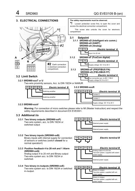
3. ELECTRICAL CONNECTIONS<br />
B<br />
3.2 Limit Switch<br />
3.2.1 <strong>SRD960</strong>-xxxT or U<br />
Two-wire proximity sensors, Acc. to DIN 19234 or NAMUR<br />
41+ 42- 51+ 52-<br />
3.2.3 <strong>SRD960</strong>-xxxV<br />
Electric terminal B<br />
Switching amplifier<br />
Switching amplifier<br />
3.1 Setpoint<br />
3.1.1 <strong>SRD960</strong>-xD (Intelligent w/o comm.)<br />
<strong>SRD960</strong>-xH (HART)<br />
<strong>SRD960</strong>-xA (Analog)<br />
3.1.2 <strong>SRD960</strong>-xF (FoxCom digital)<br />
3.1.3 <strong>SRD960</strong>-xP (PROFIBUS PA)<br />
<strong>SRD960</strong>-xQ (FIELDBUS FF)<br />
11 12<br />
Electric terminal A<br />
3.2.2 <strong>SRD960</strong>-xxxR<br />
41+ 43- 42 52<br />
Contact 2<br />
Contact 1<br />
Electric terminal B<br />
Supply voltage DC 10 to 30 V<br />
Warning: For connection of micro switches please refer to MI (Master Instruction) and respect the<br />
safety requirements described in document EX EVE0001.<br />
3.3 Additional i/o<br />
#2 Earth connection<br />
in electrical connection<br />
compartment.<br />
3.3.1 Two binary outputs (<strong>SRD960</strong>-xxP)<br />
Two-wire system, acc. to DIN 19234 or<br />
switched output<br />
3.3.2 Two binary inputs (<strong>SRD960</strong>-xxB)<br />
Binary inputs with internal supply for connection<br />
of sensors or switches (switch closed for a<br />
normal operation!)<br />
3.3.3 Position feedback 4 to 20 mA and 1 Alarm<br />
(<strong>SRD960</strong>-xxQ)<br />
Analog output 4 to 20 mA and Binary output<br />
Two-wire system acc. to DIN 19234 or<br />
switched.<br />
3.3.4 Two binary in-/outputs (<strong>SRD960</strong>-xxE)<br />
Two-wire system acc. to DIN 19234 or switched<br />
in-/output.<br />
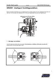
The safety requirements must be observed.<br />
*! Loosen protection screw first, to open the cover and<br />
access the electrical connection compartment.<br />
This screw also unlocks the cover for electronic<br />
compartment<br />
11+ 12-<br />
11+ 12-<br />
81+ 82- 83+ 84-<br />
13+ 14-<br />
15+ 16-<br />
81+ 82- 31+ 32-<br />
81+ 82- 83+ 84-<br />
Input 4 to 20 mA<br />
Electric terminal A<br />
Electric terminal A<br />
Supply voltage DC 13 to 36 V<br />
Bus connection acc. to IEC 1158-2<br />
Supply voltage DC 9 to 32 V<br />
Electric terminal B<br />
External power supply<br />
External power supply<br />
Electric terminal B<br />
Electric terminal B<br />
Analog output 4 to 20 mA,<br />
Two-wire system, supplied with extern<br />
power supply.<br />
External power supply<br />
Electric terminal B<br />
Binary in-/output,<br />
Two-wire system, supplied with ext.<br />
power supply<br />
Binary in-/output,<br />
Two-wire system, supplied with ext.<br />
power supply