L - VIR History
L - VIR History
L - VIR History

Create successful ePaper yourself
Turn your PDF publications into a flip-book with our unique Google optimized e-Paper software.
ELECTRONIC CIRCUITS NAVWIPS<br />
SECTION 13<br />
FREQUENCY (HETERODYNE) CONVERTER CIRCUITS<br />
-<br />
PART A. ELECTRON-TUBE CIRCUITS<br />
U!UERS.<br />
ir~c iiequer~cy~ur~vei~io~~ iu~iciior~ ili u supelileicrodyne<br />
rezeiver is accnr.p!ished either by a ~ixer circ-it<br />
with a sepmote local osc~llotor or by a pentagrid converter<br />
circuit (described later in this section).<br />
?he term mixer used in this section should not be con-<br />
fused with the term mudio mixer, which designates the<br />
linear circu,: xed to coabine sudio s1gnsis. D e term<br />
m,x.,, "b "bed i,, >t%L'",,, &>,q,k":e> " ,,u!,;!l,euc LLlcuit<br />
that heterodynes radlofrequency and locol-asciliator<br />
signals in a sgperheterodyne receiver to produce rn mtermediate-frequency<br />
signal.<br />
iri rrcriur: drsiyrr ;~ructicr, 11 is ir;i:aLir id LUIIYCL~<br />
the received r-f siqnal to or. intem.edlote frequency . . before<br />
further amplification takes place. The principle of fir<br />
quenq mnverslon and subsequent ampliflcatlon at an intemediote<br />
ireoumcv . . results in excellent seiectlvlty ana<br />
over-all gain characteristics ior the receiver. I'he trequency<br />
conversion is obtained bv the hetamdma ~, orocess, . whlch<br />
IS the cnmo!n!n: oi m inc?-ln? I=~IO-!IP~U~QZ~ SL-:E~~ +,it?<br />
o locallv , oeneroted . simal in o nonlinear device. . to oio- .<br />
duce frequencies equal to the sum and difference of the<br />
two conbinin! frequencles. The mixer stage sometimes referred<br />
to as the first detector in the stperheterodyne re-<br />
:eiier, pifom2s ,,;iv the :req2er.;y ;srve:si:; !i3;:ior,<br />
aqd must be supplied a heterodyning r-f voltage generated<br />
by n separate local-asciiiotor cirait. 'he output frr<br />
quencies of the mixer stage, in addluon to the frequencles<br />
of the input voltajes, me primarily the sum snd difference<br />
of the siqnal-lnput frequency and on inteqal rnultlple of<br />
the icccl-ilsciilotci frr:uency. Tile output circuit o! tire<br />
mixer stage 15 tuned to select only one lrequency, which<br />
is usudly o beot frequency equal to the diiference between<br />
the signal-input frequency on3 the local-oscillator frequency.<br />
This difference, or beot, frequency is known 2s the intwmediate<br />
freqency.<br />
At thls time a brief discussion of the heterodyne orinciple<br />
is helpful in order to better understand the productior<br />
a! beets ir! 3 s~oerhetendwe rece1vt.r. The occ;apwyin;i<br />
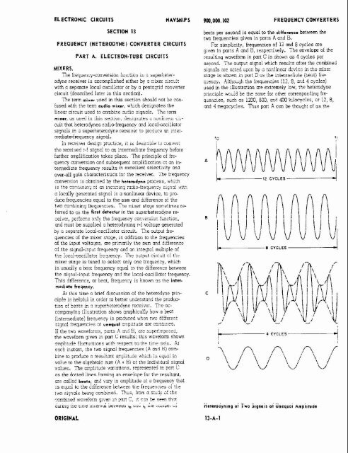
illustration shows graphica!!y hcw a k t<br />
:intermediate: . ireailen= . . is . prc:llced when twc different<br />
signa! !requ?nc!?s 3! u~~~u.zI crnpiltude ore comblnel.<br />
If the two wovefcr;;.~, pmts A ar,c 3, ;re s~perimpasd,<br />
the wovefom given in port C results: this waveiom shows<br />
lmpliti~de fiilc!uatlons wlrh respezt to the time nr!s. At<br />
r ~ nstmt, h the two signal frequenc~es (A cnl H) mmkine<br />
to prkuce o resuLtant amplitude wt,iih is ~e to the algebraic sum iA + Bi ai the indivlduili signal<br />
vdjes. The ampiltude variations, represent4 in part C<br />
oc the d"tt4 lines formin? on ~nveinp~ for the resi~itont;<br />
me called baa+., m.i vary in ampiitllde a: 3 i:eq~er.cy tho:<br />
1s rquoi to the diifererrce ktwren toe irequermcies af tile<br />
two siqnois king combined. nus, from a study af the<br />
c?-c:fis? wnve!Or!!! qlvec !n pnr! 7, I! r.11 re SDOC !hnt<br />
, .<br />
iurnlg iiir rlnlr il;icrvu; Lr~nrr~l i. uuu i, i.rc ~iu~uucr u;<br />
ORIGINAL<br />
W0.000.102 FREPUENCYCONVERTERS<br />
beats per second is equal to the dlflennca between the<br />
two frequencies given in parts A and B.<br />
For simplicity, frequencies of 12 md 8 cycles are<br />
g~ven in parts A and B, respectively. The enveicpe of the<br />
resuitirig waveform in part Cis showr~ os 4 cycles per<br />
second. The output siqnol which results after the combined<br />
5iF,~k GTe ac:ed bj G ?~n!incar irAc2 ;z :hc aixer<br />
stage is shown in pUri 3 US ihe ininntediuir ( hi) f r r<br />
3er.q. Aithc~jh :he frequencies (12, 8, cr.d 4 cycles)<br />
used in the illustration me extremely low, the heterodyne<br />
pilnciple woild be the same for other corresponding Ire<br />
quencies, such as 1200, 800. and 400 kilocycies. or 12, 8,<br />
and 4 negocycies. Tcus port k can k thought of as the<br />
L- 12 CYCLES d<br />
L z 8 CYCLES A<br />
t- 4 CYCLES -d<br />
I
ELECTRONIC CIRCUITS NAVWIPS<br />
received r-f signal, part B as the locol-oscillotoi signal,<br />
and part D os the ~ntermediate-frewency (beat-frequency)<br />
outpit of the mixer stage after demodulation.<br />
To produce an output which has very llttle distortion,<br />
the amplitude of the laally generated s~gnal must be larqer<br />
(usually at lwst ten times larger) than that oi the received<br />
r-f signal. 'This principle is shown by the previous illustration<br />
reoresentino the heteradvnina of two slanols of<br />
. .<br />
unequal amplitude. The accompanying illustration shows<br />
the heterodyning of two signals oi .qua1 amplitude, and<br />
the distortion whch results. Nclte tho! the envelope of the<br />
waveform shwn in part C drops to zero, and tho1 there is<br />
resultina distortion in the demodulated woveform shown in<br />
part D.<br />
if one of the two frequencies (A or B) being heterodyned<br />
is modulated, the same octlon os previously described will<br />
occur, except tho! the resultant waveform shown In part D<br />
will vary in amplitude ocmrding to the moduiotion com-<br />
pnent of the origin01 input frequency (A or B).<br />
Tne accumpanying block diogrom lliustrotes the heter-<br />
odyne principle of a frequency converter consisting of a<br />
Heterodyning of Two Signals of Equal Amplitude With Re.<br />
iultiny Distortion<br />
ORIGINAL<br />
WO.000. 102 FREQUENCY CONVERTERS<br />
mixer and loc31 oscillator. Two voltoges of different ire-<br />
quency are mch fed to the input of the mixer; one voltage is<br />
the r-f signal voltage, and the other is the voltage generated<br />
by the local oscillator. Tnese two voltages beat, or heter-<br />
odyne, within the mlxer to praduce an output having, in<br />
addition to the frequencies of the t w input voltages,<br />
mmy sum-and-difference frequencies. The output of the<br />
mixer includes o tuned circuit to select the desired beot<br />
irequency. The beat trequency is generally chosen to be<br />
a frequency which is the difference between the two mlxer-<br />
Input frequenc~es.<br />
MODULATED MIXER<br />
R-F SIGNAL<br />
LOCAL<br />
OSCILLATOR<br />
Block Diagram of Mixer and Local Oscilllrtor<br />
In the block diaqrom, o modulated i-f signol is applied<br />
to the mixer stoge: on unmodulated r-f signol of constant<br />
amplitude from the locol*scillator c~rcuit is also applied<br />
to the mixer stage. 'Ihe heterodymnq,or miring, of tnese<br />
two signals produces, in the mlxer output, an intermediatefrequency<br />
signal which contmns oll of the modulation<br />
characteristics of the oriainal modulated r-f sianal. The<br />
undesired sum-anddiffeience frequenc~es and the two<br />
muer-input frequencies (r-f ond oscillator signals) ore<br />
rejected by the tuned circuit in the output of the mixer;<br />
only the desired intermediote (difference or beot) irequency<br />
is permitted to pass through the tuned circuit. This<br />
intermediatefrequency signol is then ampiif~ed and detected<br />
in succeeding stages of the receiver.<br />
The lacal-oscillatm frequency d~ffers from the frequen-<br />
cy of the received I-f signal by an amount equal to the<br />
intermediate frequency; therefme, the locol-oscillator ire-<br />
quency can be either above or below the received r-1 signal<br />
and, in either case, produce the desired intermediate<br />
frequency. Depending upn the design requirements of<br />
the receiver and the frequencies involved, the local os-<br />
cillator is tuned to a irequency elther hlqher or lo'aer thon<br />
he r-f signal irequency. When the locol*sc~llotor [re-<br />
quency is below the received r-f siqcl, the following for-<br />
mula applies:<br />
ft* = fs-foac<br />
where: f,i = lntermediote frequency<br />
f, = received r-f signal frequency<br />
f,,, = locoldsc~llator frequency<br />
'%en thc loco!-o;c;!lator kequmcy is cbova the :eceived<br />
r-f slqnol, the iollaw~ng farmulo applies:
ELECTRONIC URCUITS NAVSNIPS<br />
i,f =fosc- !-<br />
?he mixer circuit includes a nonlinear element, mnsisting<br />
of either an electron-tube or semiconductor device:<br />
if an electron tube is used, the nonlinwr element can be<br />
a simple rectifier (diode), a triode, or o multigrid tube.<br />
When o triode, tetrode, or pentode electron tube is used as<br />
the nonlinear circuit element, the tube is biased at or nmr<br />
cutoff, or otherwise operated on a nonlinmr portion of its<br />
choracteristlc curve. Triode and multigrid electron tubes<br />
used as the mixer in superheterodyne receivers genemliy<br />
produce some signal wplification (conversion gain), in<br />
addition to the desired frequency conversion. A discussion<br />
of similar nonlinear elements is given in Section 11,<br />
Pptwroi (llemnd~~lator) Circuits.<br />
her-iocal oscliiotor mmblnatlon circuirs con provide<br />
reasonable frequency stability in superheterodyne receivers<br />
up to opproximotely 500 mc. Tne mixer circuits<br />
Ipsnibed in this section are representative oi typlcol<br />
elmion-tube mixers found in many mmmunication-elec-<br />
Ironic equipments.<br />
DIODE MIXER.<br />
APPLICATION.<br />
?he diode mixer is used ir. superhetemdyce receiver<br />
clrcuits to combine, or "mix", the r-i signol from a local<br />
oscillator with the incoming r-f signal, in order to produce<br />
the desired i-f (intermemate-frequency) cutput signal.<br />
The electron-tube diode mixer is generally used in appli-<br />
cations where slgnai-;@noise rorio is an imporiuni m~l-<br />
sideration or where the transit time at very high irequen-<br />
cies becomes critical for other types of electron-tube mixers.<br />
CHARACTERISTICS.<br />
Requires o separate iocal-oscillotor circuit to supply<br />
the heterodyning voltage.<br />
IT.:^:<br />
,,,,,zes the prinaplc o! re~;!icollan by z noc!:nea:<br />
device.<br />
Output circuit is tuned to the difference frequency, 01<br />
intermediate frequency.<br />
Conversion gain is less than unity.<br />
Signal-to-noise ratio is gmd.<br />
CIRCUIT ANALYSIS.<br />
Ganwal. The diode mixer is one of the simplest types<br />
;i Eixei ;;i;w;; empioycd a; 3 frequency con,!rr!er. ir:<br />
.L:. ,i,> applicotior., vcltojes sf the two input !req;mcies !c<br />
.- ,j :re 2Gp::& :, :ez& : :k.c ::25.+, y.2 :ke<br />
& kt*, ,&"; ."* y,.c<br />
mixerilutput voltage is obtained from a tuned transiormer<br />
di ; m ~ l ~ , c s ~~~~~~~~~:. - ; ~ Zb.e -;:PC 7:rc-:: :<br />
tuned to the dliterence frequency (~ntermd~ote trequencyj<br />
so that it will pass :his !;cqency on to the scwsdir.;<br />
i;,tc:mediate!;equency amplifier stages bc! wi! -tten)~mz<br />
(teje-3) ail other irequencies.<br />
The electron-tube diode used as o mixer is subiect to<br />
eiiects die important, the crystal diode is fiequentiy ised<br />
-"-:yrr :,.,.-: -.-..-I .'~<br />
J.->.<br />
,., ,,I-,-,-,#.'- , #<br />
~> -..--- L.<br />
illCr,c~~ll",-,i,uli,,i.,r.<br />
Circuit Operation. "ji;;,j:e %ode mixer c~rc;:: is<br />
illustrated in the ocmmomvina circuit schemotic. Trons-<br />
WO.WO.102 FREQUENCYCONVERTERS<br />
former TI consists of an untuned primary winding and a<br />
tuned secondary winding: capacitor Ci and the secondary<br />
winding of TI form o resonant circuit at the frequency of the<br />
i-f signal to be received. Transformer T2 is similar to Ti,<br />
except that capacitor C2 and the semndary winding T2<br />
form o resonant circuit at the frequency of the iccal-os-<br />
cillotor signal. The resonant circuits, shown in the sche-<br />
matic os TI. Cl and T2. C2, are actual L-C circuits mm-<br />
posed of inductors and capacitors at all radio frequencies<br />
up to the ultra hiqh frequencies. At the ultra hlgh frequen-<br />
cies and above, the tuned circuits may be in the form of<br />
tuned lines or remnant cavities.<br />
Electron tube V1 is a cathodetype diode; the ilioment<br />
-<br />
lheateri circuit is not shown on the schemotic.<br />
ironsiormer T3 is a doubie-tuned trmsiormrr, with the<br />
primmy and secondary circuits resonant to the output<br />
(intermediate) frequency. This transformer exhibits a<br />
bcmdpass chmocter,stic and thereby dlscrimlnates oqalnst<br />
frequencies above and below the desirea output frequency.<br />
R-F<br />
SIGNAL<br />
INPUT<br />
OSCILLATOR<br />
SIGNAL<br />
INPUT<br />
Diode Mixer Circuit<br />
FREQUENCY<br />
SIGN4L<br />
OUTPUT<br />
'then no r-f signal is applied to the Input of transformer<br />
TI, but the lacol-oscillator signol is applied to the input<br />
(primary) of transiormer T;, diode '
ELECTRONIC CIRCUITS NAVSHIPS<br />
increose arplituit ..:hen approachir; sn in-pt.ase relotlonship<br />
ond to decrease cnplitilie .:+her, cpproochlnq or, outof-phase<br />
relaticrsiip.<br />
Because tne two slnc-..,>oi.e freq~enc~es are superimposed,<br />
the mlxer diode rectli~es, or detects, inth frequencies.<br />
As o result, p~1satin.l corrents hnici vory in omplitude<br />
ot the beat-freqcency ro:c ore F~O?UC~? ~r, the primary<br />
of transforn,er T3. Txi, (1 ~or~~ei envelope is formed<br />
which vories in occordancp with tne difference frequency.<br />
The pulsating currents forntinq the carrier envelope flaw<br />
thiough the pnmary r;lr,dlnq of transformer T3. Since the<br />
primary circult is P~ned, it presents o hjh impedcnce to<br />
the difference (intermediate) frequency. Consequently,<br />
this frequency is passed by tror.s!orner T3, and a voltaqe<br />
is induced in the secondary wirdinq which vories in onplltude<br />
in occordince with the ar.plituce of the oriqincl r-f<br />
signol.<br />
If the received i-i sipol contoins omplitde-modulation<br />
components, tile beat cifference will olso contaln arnplitudemodulotlon<br />
cornpcrents, which vary in accordance<br />
with the audio frequencies rodulctinc the oriqir.01 r-f s~qnal.<br />
If thc rece~ved r-f sicnal is frequency-modm~lcted, the<br />
beot difference will devlote at the same rctes os the ariainol<br />
r-f siqnol. 'Thus, it is seen that the charocteristics of the<br />
inter~>ediate-frequency slqnal are the someos those of the<br />
oriqlnal received siqnal, except that the frequ~ncy of the<br />
rece~ved s~gnal has been "converted" tu a lcwer frequer.cy.<br />
'The output siqnol voltaqe developed across the secondary<br />
tuned circu~t of tronsfornler T3 is applied to succeedinq<br />
intermediote-frequency amplifier staoes ond is subsequently<br />
detected, or demodulated.<br />
FAILURE ANALYSIS.<br />
Gsncrol. Since the clrcuit of the diode mmrr is relatively<br />
simple, failure of the circult to operate can be re<br />
solved to one of several possibilities. The diode, V1,<br />
should be checked to deternnne whether it is in sotlsfocory<br />
condition and whether the correct filcn~ent (heater)<br />
voltage is applied to the tube.<br />
The presence of an r-f siqnal (or o test siqnol) and the<br />
local-oscillator signol nust be determ~ned, since no output<br />
can be obtained from the mixer circuit unless bath,<br />
signals are opplied to the mixer input. Resanont circuits<br />
TI. C1 and Ti, C2 must be properly oliqned, each to its<br />
specified frequency. The doubletuned output transforrrer.<br />
T3, must olso be correctly tuned to the desired intermediate<br />
f~equency. Since one or more open wlndlngs in the<br />
tuned ciicuits (TI, T2, and T3) con cause a lock of output,<br />
these windings should be c5ecked with an ohnlmeter to determine<br />
whether continuity exists.<br />
TRIODE MIXER.<br />
APPLICATION.<br />
The triode mixer is used inreceiver circuits to combine<br />
or "mix" the r-f signal from the local osc~liotor w~th the<br />
incoming r-f signol, to produce th:e desired interrediate<br />
frequenq (I-FI output.<br />
CHANGE 2<br />
0967-000-0120 FREQUENCY CONVERTERS<br />
CHARACTERISTICS.<br />
Requires a separate local oscillator ci;cuit to supply<br />
the heterodyning voltoge.<br />
I-F frequenq remains the same for any selected input<br />
frequency.<br />
Operates on the non-linear portion of tt.e Errlo curve.<br />
Has an amplification factor, ,which is referred toas con-<br />
version gain.<br />
CIRCUIT ANALYSIS.<br />
Ganerol. The purpose of the nixer stage is to convert<br />
the incoming r-1 frequency, usually into o lower frequency,<br />
which contains the some charocteristics (modulotion) as the<br />
original r-f frequency. This lower output frequency, called<br />
the intermediate or i-f frequency, remains the some, regordless<br />
of the frequency of the r-f signal received.<br />
By operating over the nan-linear portion of the tube's<br />
characteristic Eg-Ip curve, harmonic distortion is produced<br />
in the plate circuit, and as o result of this harmonic distortion,<br />
new frequendes, ,which are ham,omcs of the input, ore<br />
introduced. By proper selection of the !ocal oscillator<br />
frequency, specific output frequencies can be obtained.<br />
This mlxing of frequencies is called b.eterodyninq, and the<br />
result ot the plate is the presence of four basic frequencies:<br />
Namely, the sumand the difference of the two inputs, and<br />
the two original lnputs (various other beats are olso produced<br />
but are not often used particularly becouse of the<br />
small amplitude remclnlng as compared with the basic outputs).<br />
A resonant tank in the plate circuit is tuned to the<br />
selected difference frequenq, so thot it will pass only this<br />
~ ~<br />
frequency on to the succeeding i-f amplifier stages and thus<br />
effectively attenuate all of the other beat frequencies.<br />
Circuit Operotion. The accornponyinq circuit diaqrm<br />
illustrates a typical triode mixer.<br />
L2, the secondav of TI, together with C1, forms a tank<br />
circuit tuned to the desired r-f frequency, and this selected<br />
1-1 signal is applied directly to the control grid of tube V1.<br />
The tube is biased class "C" by the use of Ci and R1.<br />
which forma cathode bias circuit, and it is for this reason<br />
that the tube operotes on the non-linwr portion of the ETIP<br />
curve. Thesignol from thelocal oscillotor is coupled<br />
through tronsformer 'E to the cathode circuit of the tube,<br />
and because the tube operates on the non-lineor portion of<br />
thechorocteristic curve, the two input siqnols ore mixed.<br />
'The result at the piate is a s~qnol c0ntainir.q the sum and<br />
difference of the ?NO inputs, plus each of the tvin originally<br />
applied signals. The primov,L3, of T2, toqether with C4,<br />
. ~<br />
forms a tank circuit tuned to the difference, or i-f frequency,<br />
and capacitor C5 bypassed . . the unwanted r-f frequencies to<br />
ground.<br />
With no r-f signal applied, and with the siwal from the<br />
local oscillator applied to the cathode circuit, tube Vl conducts.<br />
The current through the cathode storts charqinq<br />
copacitor C2, but because of its long tlme constant, the<br />
ojcle ends before the copocitor can ch.arqe to the peak<br />
value of the input. The charge is slow to leak off, however,<br />
hecause of thevalue of 81, and i%,ith~r, a few cycles, the<br />
cathode circuit stobillzes at a voltage which determines
ELECTRONIC CIRCUITS 0967-000-0120 FREQUENCY CONVERTERS<br />
3h@<br />
r-f<br />
NPUT -<br />
-<br />
-<br />
I<br />
I<br />
I<br />
MECHANICAL<br />
COUPLING TO LOCAL<br />
OSCILLATOR<br />
T -<br />
Typical Triode Mixer<br />
u<br />
the operatinq bias of the tube. For odCitior.cl inforration<br />
32 ccthode Lies, :e!nr t? tcctic?. 2, ;=:c;:o;i 2.2.1 7' :l-r<br />
Handbook. Because of the larae cott.ode bias. the t.~be<br />
operotes c!css "C". ~ n tk~s ? over tile na5:lnear portlor ?!<br />
me Eg-Ip curve.<br />
Capacitor Cl and the tunlng capacitor in the locol osclllator<br />
are mechanically connected, so !hot wherever the<br />
." Ci . . .<br />
;S C-cn;e< ope:Ctc :.: ... "" ", " ""...Lu~b. :.<br />
frequency, the local oscillator tank is clso ct:mged autcmatically<br />
by the some orcount. ?,is results in the locol<br />
oscillctor !requc?cy acd :kc r-! !rquer.q akyc '.sir;<br />
seporo:ed by the same anount at my frequency .Ni-.ici mcy<br />
be selected at tine input. me ompi~rude oi !if. local oicil~<br />
.""' I".". .."I.""" .- :- """."y;-".~,..<br />
"p"id._ . > .-* .-.. +:.o? i_..__ .. --. -.--* "" *L* ...<br />
r-f signal amplitude, for e!iic~ect zixinq cr.2 the ireq~cncy<br />
is selected either obove or beivi: the r-i frequency, iependin3<br />
apon t:,c ,2c>!i,-,;acr, . . 2: !!',? ,-::c:.:t. , 52". . ,>n ,;-c:.-,t ;.!I+<br />
1s eqaai to the I-: ir~q!~nr:.<br />
. . o~:#!c~ cyrot!n.q ?~?C!!!C~S f"~ fzL{x:;!p," :"..-"<br />
takes ploce. Tre :zp';t :-f irequezcy an6 t!.e lccai osiil-<br />
?"*,. ........ f .-I,- ,. ",". .,.. ,..- ..< ..,,, !,,." ........ -,,.. !, "-":."A *- ,L" -,2 "-2<br />
.??... ................<br />
, .<br />
carnode ii~iuits, iesp~it.~.eq. ns piwio~sly r:enaorei,<br />
,hmcr " . ,.,.,. :--.;.; ,' ':"',..-. '.-; n--:;; . -I -,--.<br />
73"j ir !be:: 3t~se<br />
sq~ent?y, they ~eriodicolly<br />
:e!r;tioc-<br />
Snips wltn eucil otiier. For lills reoson, they oCd or s u ~<br />
tract algebro~colly at requlo; intervck, and tile result ot tt.e<br />
plate 1s o nelv s1gn0i whose a~ipiit~de varies at a ~teoiv<br />
rate. Tnis vorlatior irt cn~p!itude is a! prinor:, impcrtnr-~.,<br />
....<br />
md is inour os tie "6-at-ir~qnercy". Tr!; '%PO:-<br />
. . . . .-",,.~, . . . . . . . .Po.....-.-.-- .."",,rn*?., -" . "- ..-y--.,u, .....-. ........<br />
-..-, ..... .--...,, ...<br />
results fro- the olqebrric oddition o! !he t.::o ineuts as tt.ev<br />
approach an in-pirose relotionshlp, and tt:eir subtractior os<br />
they . opprooch on out-of-phase relotionshio. This seat fre-<br />
~~<br />
qumcy is equal to the desired i-f frequency.<br />
The resultinq plate clirrent pulses, whose am2litcdes<br />
vary at the beat-frequency rate, orrive ot the primary of trunsformer<br />
TZ, n d a carrier envelope which varies at the beat<br />
(i-f) frequency is developed. Since the primory of T2 is<br />
tuned to this i-f frequer.~ . . by . the use of CA, . it cresents .<br />
a maxirnumlood to the plote at tt,e i-f frequency and the<br />
chonginq field thc: is developed around the primory ,winding<br />
induces an output in the secondow. All other bect<br />
frequencies present in the primcri are IO! develo?ed, be<br />
.-n,,.P the ~t-?~iiir~~.<br />
tn there f,F;llCT^jeE j~ C! n<br />
For o detoiled descripuon 01 the 'leterodvnina . . actlon, re!er<br />
to t.e i:.trodjction to tk.is sectior, of tt.e Hondbok.<br />
If the received r-f simal mntoins molitude aosuiared<br />
m-*mmom ,- .%L" LO". 4 .-,,on -" ...F-..-....., ... " "., "I-* -",.,":"" .:-.;,-.<br />
.,u7 ... "" -" ... " ....... "~ .... "..<br />
tude modulated cornnonents, which varv in accordance wltt.<br />
theaudio freque~.cies modulating the original r-! sipal. If<br />
the received r-f jianal is freouencv . . modulated, +,e beat diiference<br />
will deviate in frequency ot tb.e same rate as the<br />
origin01 r-f slqnol. '?,us, the charccteristics of the I-:<br />
signal ore the same as (hose of the 01iql~,a1 received<br />
slQnal, except tho! tine irequency of the recP?ved slqmai is<br />
converted to o lower !requerq.<br />
A commonly used circuit variation of the triode mlxer<br />
applies bth the locol oscillator and r-f siqnals to the arid<br />
of the tube. There is little ooerationol difference. but<br />
-" ""t$"Ae , uu *,,; .,*"T, pr3
ELECTRONIC CIRCUITS NhVHIIPS<br />
lator with an oscilloscope to make sure that it is of proper<br />
amplitude.<br />
A distorted output can be caused by o defect in nearly<br />
any component in the circuit. Check for the presence of<br />
the r-f signal on the grid of V1 with an oscilloscope. If<br />
no signal is present, check for a signal on the piimory of<br />
TI. If the signal is present on the pri-rcry, check the trans-<br />
former windings .xith on ohrmeter for on open or short, and<br />
capacitor C1 for a possible short. If no signal is present<br />
on the primary,the trouble lies in the preceding r-f ompli-<br />
fier stages, and the mixer is probably not defective. Check<br />
for presence of the local oscillator signal on the cathode.<br />
If not present, check for its presence on the primary of<br />
transformer T3. If not on the primary, the trouble lies in<br />
the oscillator circuit,and the mixer is probably not at fault.<br />
If the signal is present on the primary, check the secondary<br />
of the tronsiormer for a short or an open, and check R1<br />
and C2 for proper volue. If both the local oscillator and<br />
the input r-f signals are present at the grid and cathode of<br />
the tube, the trouble is in the plate circuit. Make certain<br />
that the plate tonk circuit is tuned to the propr i-f fre-<br />
quency. Check C5 wirh an incircuit capacitor checker to<br />
determine if it has changed in volue. Check the windings<br />
of T2 for a partial short, as this con change the resonant<br />
frequency of the tank.<br />
PENTODE MIXER,<br />
APPLICATION.<br />
The pentode electron tube is used os a mixer in suoer-<br />
heterodvne receivers to combine, or "mix", the r-f sional<br />
from a locol oscillotor with the incominq r-f siqnol, in<br />
order to produce the desired intermediate frequenw !i-0<br />
output signai.<br />
CHARACTERISTICS.<br />
Requires a seporate local oscillator circuit to supply the<br />
heterodyning voltage.<br />
Output circuit is tuned to resonate at i-f frequency.<br />
Plate resistance ond tronsconductonce are fairly hiqh.<br />
Operates on non-linear portion of Eg-lp curve.<br />
Output frequency (i-f) remuins constant under normal<br />
operating conditions.<br />
Has a relatively high conversion gain and siqnal to<br />
noise ratio.<br />
CIRCUIT ANALYSIS.<br />
General. The pentode mixer is frequentlv used in f-m<br />
equipment for the v-h-f bond. At frequencies where the<br />
screen grid is eifective, thepentode mixer provides qood<br />
isolation between the input and output circuits. This means<br />
reduced input loading and elimination of possible instability<br />
as compared ,with o triode miner. The oscillator and signal<br />
voltages ore usuoily applied to thecontrol grid simuitane-<br />
ously. In this way, a noise fiqure is obtained which exceeds<br />
thnt of a normal pentode ampliber, but which is much lower<br />
than in any of the multlgrid mixers.<br />
CHANGE 2<br />
0967-000-0120 FREQUENCY CONVERTERS<br />
The pentode has an extrerrelv hjgr. conversion tronsmnductonce<br />
ond per-r~ts higt, ,voltaqe qoin in the mlxer<br />
stage. The equivalent noise voltage produced by !he tube<br />
is twice tht of a trlode mixer of tie saxe trarsconcuctonce.<br />
Becouse of the b.igh obtainable trorsconductcrce of pentodes,<br />
the overall perforrrance con exceed that of xost<br />
triodes. Since the triode bas 3 certain amount of stray<br />
mupling between grid and plate c~rcu~ts, ~t is at a disadvantoqe<br />
in this respect when camPored with the ~entode.<br />
At the signal frequenq, the i-f circuit 1s capacitive, and<br />
this, because of Miller off-ct, ~esults in o reflected low<br />
resistance in the grid circuit. The screen in o pentode<br />
effectively stops tiiis Ioodinq. With a pentode, cathode<br />
injection of the oscillator signol is possible, but this<br />
mode of injection increases the effective cathode inductance.<br />
Since the input lood is proport~onol to tne catt,ode<br />
inductance, cathode injection lowers the voltaae aoin of the<br />
input circuit 2nd also te noise performance. Tke stability<br />
of the oscillotor, however, is ~nproved at very-hig5 fre<br />
quencies, where c 10.~-lmpedonce oscillotor load is needed.<br />
Unless the oscillator and mixer are looselv coualed,<br />
interaction and pal!inl: becomes severe. Interaction of the<br />
oscillotor and the s~gnul is greatest wher they are both<br />
applied to tie some qrid. Similorly, oscillator radiation<br />
becomes o greater problem; however, the hich transconductance<br />
of the pentode permits the use of small oscillator<br />
mlrages, and radiation is not as qrea: a problem as in a<br />
triode.<br />
In operation, the use of a pentode as o mixer is similar<br />
to the use of a triode as ,a mixer. However, the use of o<br />
single grid for both the carrier an? locol oscillator siqnals<br />
sometimes gives rise to difficulties resultinq !rorr, couplinq<br />
between the csrrler input c~rcuit and the local osc~liotor<br />
circuit. Using the pentode as a mixer, onesignal may be<br />
applied to the suppressor grid and the o!i.er signal to ti.e<br />
control grid. By applying the input signals to separate<br />
grids, it provides some isolatior between the localoscillator<br />
ond r-f signals. Tnevoll:c of thecathode re<br />
sistor is chosen so that it will cause the tube to operate<br />
on the non-linear portion of the Eg-ip curve (the lower bend<br />
of the reponse curve). T?e plate cxrent of the kbe then<br />
contains the two original ]?put frequer,cies as ,well as the<br />
sum and difference freqdencies of the two original siqnols.<br />
The signal from the locol oscillator is nom,olly mode much<br />
suonqer than the r-f input slqnd so that the percentace of<br />
modulation is kept law. The Ion, percentoqe of modulation<br />
required for irequenq conve:slan car. be produced in several<br />
wws. The method most frequendv used depends on the<br />
umsier characteristic of a tube or other c~rcult element.<br />
The transfer charncteristic expresses the relationshio be<br />
tween the simal oppl~ed to the input of 0 dpv~ce ond the<br />
signol obtained irom its output. The trorsier characteristic<br />
oi a vocuum tube is not o straiqtat iine, slnce the relationship<br />
oi Eq to ip usually is curved 01 low wlues of plate<br />
current. Tnereiore, the vacuum tube is o non-linear dence.<br />
When the wltoqe on the qrid of a vacuur tube becores<br />
more negative and reaches the plote current cut-oil volue,<br />
no current ilows in the pl~te circult. Consequently, for an
ELECTRONIC CIRCUITS NAVSHIPS<br />
entire rmGe of vo!tages :.c mrrent f:c.;:: ir. the 1r;put arc'it<br />
Therefore, :i..e v:cl>rn tiSe IC :on-l!'ie;r, even if its :rcns-<br />
fer characteristic 1s periecdy st~01:t.t.<br />
Circuit Operotion. The schemotlc of o typical pentode<br />
nixer arcuit :E sto:\n :r the zccatmpar.;:r.j i1l~:tra:icr.<br />
4%-<br />
TO LOCAL<br />
OSCILLATOR<br />
t<br />
0967-WO-0120 FREQUENCY CONVERTERS<br />
31 the incarn~ng r-f SI(JT~! ,!o!I~;E.. --.e !OC~ os~iIIatcr<br />
Irequerci is eiti.er obve or bela- tt,e ?esired i-i frequencv<br />
(depending on tt.ecircult oppl~cotlon), by a" ornomt."hiciis<br />
equd to tile desired i-f irauen~.,.<br />
Since t h two ~ applied sl~n~15 differ in freo~enci, their<br />
voltaqes 3fF rct cI.:;;is 111 ::.3re :..I: ~ 3 ;t?,er. ~ 5 Ferio-1icaliy<br />
these two -;c!tG;es algen:xcz!!y cd: a: ~-~:ract tc<br />
produce an ompli: : i~ I.J:!7t11 :I :em!c: ~ ~ I C ~ V C I S i: : is this<br />
per~odlc nmpiit~re vailgtior 17 :ie for-31 1 k;nct fiqu~nc:'<br />
.io!toge iihcn is a: ireotest inpartance. Plebeat frequeno<br />
is actucl!y ti.," ?iffereccp ire.; :w:y pr?ilAce? :y !he 1rstcntoneo.;;<br />
z;::r,o: voltaji: ;i :Lq corilhne to incrense<br />
ompl:t ice wrm ~~T-,~C:II:I~ C? :n-rkos~ :elctlonshi~; and<br />
to decrease when aauroach~na on out-of- hose relotionshio.<br />
I! tile irlcurlliily i-i algnui cuncwns urnyi~tudc mujuiuced<br />
; ~ f ~ r 3bn ~ :eF#>ltin" ~ ~ ....... i ~ ha,!, n .................... -.-, .,.,,I "Ico -nn,7:"<br />
, . . .<br />
.- .. -.<br />
,:,e sc::: -:.; ::;a- .. ..-.. - .,; .d..C7. i>iS 'z~o~,Gdoc<br />
vcr[o; :q :r-cr-,T. "? .... *L .LA ..,, - A:" f .,.- ,<br />
lotin? lncomlnc r-i sl~.cl. It tne receive: r-i s:moi contains<br />
frequercv :?o~L!c!P; ln!om3t1on, the beat !requencv<br />
I -<br />
t<br />
Ebb<br />
miference ~ lii le~inte CI !/essnr:e mte cr tie incomnc<br />
.- , ,<br />
f I e c . .-;s :re ~:.=ccteristi:s ii :'ZC res,,,,e"<br />
.>>...., :.r . ". *:* ...-..... ......-.--'.>- ,: ............ ,.,r -.. . ", ,u., .,:, ". !-! s:,:r>,z;,<br />
except t5.31 tL: i:nq:e?.q ^! :be TC-CP!!~? s:=c! Las tier<br />
Typical Pentode Mixer Circuit<br />
cc?.':e:::c tc 7 !?','c: 2: ?.:;?.c:<br />
applicct~cn.<br />
::cq;e?c; :c;?:,::::: ':;ST :.%<br />
Transformer TI conslsts of an untuned prirnaw windinq<br />
As a result o! the ieterodymnq action tokinq &ace<br />
and c tuned secon?oq, .wind~n~: capacitor C1 ord the<br />
within the elements of the tube, the output signals present<br />
secondary winding o! Ti form c resonant c~:cu~t at the<br />
at the ?late of 'dl xi.: !be c;:: : !.!.o ir.put s;ano;s, the<br />
zir: ... e. .. -. . ......... . ---#. . .<br />
!rsyx-c: z! :be r~! ;:-c: :c ?e IFCD~\.C.C. E!ec!rc: ?he<br />
>e..cc ,. --. .... ..,.?<br />
,..c ..., .... : ; .,..-. -, .... .,,c ...u,r,jit s:-<br />
V1 ic a pe~ttade: !k.e fllnre!:t (heater) arcuit is not shone<br />
nals thernse!:.fi. S:nce t?i zrl:::::; ;;li.iiro af t:irsforr~i<br />
3rr t!,es^it:.~::~.<br />
T2 IS tuned, it .i:; oiesert r '!,i i-p=dl,v- tn t k rlesirej ~<br />
- .<br />
After bemq . ::plifled in ;Ee step-up ircnsformer Ti, the . , , ; , . . ', '.? .".. ~<br />
r-f siqnal is applied to the G:? of :nlxer tube V1 alonc<br />
with the local osrillcto: s:qnol +;~-Ic-I I? applied tlroJ$h<br />
"" ".<br />
ci..?p;i!!l .g> ,Jc: ;>. -.,.,< :ikc c.lp.c;:.r 2 ?sclc!.. 6 -.<br />
contac! bias resistor HI iram !i.e slgrol source. Screer c,j~<br />
pass cop3c.tor C.l has a low enou~hreactance to place the<br />
screen n! :roun.? pn!e?t!?i. kpnir? rei.!s!nr F2 ?e!ermi~es<br />
$?e screen L.C!:.:;: I: ~ L c ;~.:.:FF 7::: if \I!. k i ~f kv-ip~ss<br />
.-,. .-,,* ;;" *.-,,, 2<br />
,.r,..u,,.- ,- r,uv.uc:: .. :;.-r--.,-. "" t 1s proro:!1on(11 to !w cot-?de !L~?JC~~C~.<br />
...................................<br />
LYLI.j"I<br />
L.,,LLI.U.. ...>a .U..., ... i .i.il.C i"il. ", L.IC_,.IYL<br />
. -. .. - .. , - , - - .<br />
. ............................. . . -. .<br />
L*,L,a~L",,,A"."" .. L ............................ L.<br />
, ., . , ,. .<br />
~ .~ ~. ~.~ ~~ ~<br />
................. 1..-2.. -" p..I-.. .... .". - .<br />
o'*;. '"......-..&-en -.G -.:-. -L..-<br />
. i.re:rib.L ...- . CLdl.L. . i ~ . . L . .,e;..;.. l.sa:,rc.<br />
, , . . . .<br />
I -.-.... . -..-L.>:s2 .. L . .L .(.;".".<br />
picvidei i ieajt:.;e t:i: or 15 f.: i. .:;bilk .i ;:>:<br />
FAILURE ANALYSIS.<br />
contoct-porantlal was. ~opoeltor -L cncrq-s to tre YCLT-<br />
. ,.<br />
,-<br />
,..-.! ....<br />
1 tr,.,;... *!^ ,,La -.,,^'I<br />
No Output. -c:c::..= :.L:, :.. uy::. -: - , - .<br />
::.:::-: :I,<br />
. - ? - .~.- , -, , .. - ...-........<br />
. . Ch, or Cb, or a neiectl~!c I I or !L ;m ccouse o ro-o':tput<br />
Varyir.5 cnpcritcr 7i ::yes 5e !cnk clrc.:: !e ire 1~<br />
.:.A>: :... E Y:- 7 :----!.I;.J :. condition. aeck ['he plote 3! Vl w:lh a kigh res~stonce<br />
>.,cu .l,~"lir.. . ,-. ..-...... ..+."~ "...,,L.L.=d .I. aLcr-<br />
,r ...... voltmeter. I! plate vnlto?e !r not present, ilse on ohmmeter<br />
li, i<br />
Ti, y;,: ,,: 3ppi;ed to 11; cor,!ro: qrlr a! VL,<br />
up transiorr~r<br />
:lor," , ,..' . ' ti. ! " I , . T-e ?:.;:!!;,{" li !:.?<br />
, ............. ____- .. " 7 , 7 . . . .L I<br />
........................ ..- ........ i - . . .<br />
-<br />
CHANGE 2<br />
... ..<br />
to check the ccntir~ty 3f th,e ;::xory .r,indir.j of E 3~1";~<br />
check C!. C5, zr.: CE. !cr 5 -no:! 0: -:ez 1cz3:::oz. !!
ELECTRONIC CIRCUITS NAVSHIPS<br />
the previous checks foil to locate the trouble, the circuit<br />
supplying the plate voltage is probably at foult.<br />
Lor Output. A lo,^ output -~o,uld lormally be caused<br />
by a defectj,,e or weak VI, or o low filament or plote volt-<br />
oqe, or lf the i-f ond r-f tsnk circlits ore no! tuned to the<br />
proper freq~encies. A ;:eck local oscillator voltoge cln<br />
cause a low output. Check the flloment and plate voltages<br />
wlth a VnM. If they art. not riornnl, refer to the procedure<br />
in the previous paragraph. If they ore normal, check the<br />
amplitude of the loco1 oscillator signol. If it is low,<br />
check C3 with an incircuit copocitor checker. If the out-<br />
put is still low, the trouble is probably in the local oscil-<br />
lator circuit.<br />
Distorted Output. A distorted output can be caused<br />
by a defect in nearly any component in thecircuit. With an<br />
oscillascope, check far an r-f siqnd on Cqe secondary<br />
winding to TI. If the r-f sign01 is not present, check the<br />
windings of T1 with an ohmmeter for continuity. Should<br />
the windings not be defective, the trouble lies in the pre-<br />
ceeding stages and the mixer is probably not defective.<br />
If the signol is present on the secondary winding of T1,<br />
check for the presence of the local oscillator signal on<br />
the high side of C3. If it is not present, the loco1 oscillo-<br />
tor is at fault. If it is present, both the I-f and local<br />
oscillator signals should be present on the control grid of<br />
V1. If the local oscillator signal is not present, C3 is de-<br />
fective. If the r-f signal is not present, C2 is defective.<br />
If bath the r-f and local oscillotor signals are present on<br />
the control qrid of V1, Tube V1 is probably defective. If<br />
the output is still distorted, check the plote and sneen<br />
voltages with a VTVM. If both voltages are low, check<br />
the outplt of the plate voltoge supply. If it is low, the<br />
trouble lies in the plate supply. If it is normal, and the<br />
screen voltage is low, check R2 with an ohmmeter, and<br />
C4 and C5 with an in-circuit capacitor checker. If the plate<br />
voltage is low, check C6 with an in-circuit capacitor checker<br />
and the primary winding of T2 with an ohmmeter. If the out-<br />
put is still not present, check the secondary windinq of T2<br />
with on ohmmeter.<br />
PENTAGRID MIXER<br />
APPLICATION.<br />
The pentaqrid mixer IS used in modern superheterodyne<br />
receivers 0s o frequency converter. Incoming r-f s~gnals<br />
are combined wlth signals iron! .I local oscillotor to prm<br />
duce an intermediate frequer:~; (i-f).<br />
CHARACTERISTICS.<br />
Offers qood selectivity.<br />
Serves both os a frequenq converter md o hizh qain<br />
amplifier.<br />
Siqnal-to-noise rotio is poor.<br />
Requires o separate local oscillator to supply the iet<br />
erodyning voltage.<br />
Uses two input control q ds to provide electron mu-<br />
plinc.<br />
CHANGE 2<br />
0967-000-0120 FREQUENCY CONVERTERS<br />
Operates with either cnthode-self, flned, or ovc bias<br />
voltage.<br />
CIRCUIT ANALYSIS.<br />
General. Tne function01 operation of the pentaqrid<br />
mixer is very similar to !hot of other mixer circuits discussed<br />
previously in this hmdbook. R-f and oscillator<br />
voltoges ore injected into the tube a d added olgebrclcolly.<br />
The fundomertal ireqljen-~s, along vrith their swm and<br />
difference frequencies, appear ocros: the outout circuit.<br />
The output circuit is a parallel resonant tank, tuned to the<br />
i-f. The desired I-f sional is transformer coupled into the<br />
next stage.<br />
The prlmary difference between the pentamid mlxer circuit<br />
and other mixer circuits is the input arrangement. In<br />
the diode, triode, md pentode nlxer the r-f md oscillator<br />
wltoges are inserted on the same tube element, allowinq<br />
for greater ~nteraction between input signals. In the pentogrid<br />
mixer, r-f and oscillotor signals ore inserted on seporate<br />
control grids, isoloted from ear5 other and the plote by<br />
screen grids. Coz;eq'~endy, the frequnq pulling effects<br />
md signal interocticn, cormon to other mixer circuits, is<br />
virtually eliminated.<br />
Circuit Operotion. Before discussinq ooeration of the<br />
pentogrid mixer it ..will be helpful to review :he operation of<br />
the pentagrid tube.<br />
The pentagrid tube consists of a plote, cothode, filaments<br />
and five gr~ds, hence the name pentogrid. Two of<br />
the grids ore used as control grids (GI and G3), two are used<br />
as screen grids (G2 ond G4), and the fifth is used as o<br />
suppressor grid. For all procticol purposes the gain of<br />
the pentagr~d tube is compcroble to that of the pentode,<br />
however the inuoductian of an extro screen grid increases<br />
the partition noise, and consequently, the circsit noise.<br />
The screen qrids are operated at a positive voltaqe and<br />
serve as the occeleratinq anodes for electrons leovinq the<br />
cathode. However, the electrons strike the plate of the<br />
tube wlth such force that they tnunci off (semndory emission)<br />
and form a spcce chorqe around the positive sneen<br />
qrid (G3).<br />
The space charge greatly limits the plate voltoqe swinq,<br />
so a negative grid (G5) is placed between screen and plate,<br />
md its negative charge diverts electrons jock to :he plote.<br />
By following the above discassion it con be seen that<br />
the pentagrid tube plote current is made independent of<br />
plate voltage. In fact, tile plote voltage may smng as low<br />
as, or lower thm, tk,~ screen voltoge ..xithout serious loss<br />
of amplifier qoir capobil~ties. In rnixer clrcuits jnin (qr)<br />
is referred to os "con,,ersicn transmnductance" ond rep<br />
resents the quotient of i-f octput current divided by r-f<br />
input voltage; a:, conversion trunsconductance = Iit/Eri.<br />
In pentagrid tubes con.Jerslon trarscond~ctance may run<br />
as high as 500 micromhos.<br />
In the mixer circuits previously discussed, such as the<br />
triode ond pentode mixer, the r-f and oscillotor siqnols ore<br />
injected on th.e some control grid. Tnus the r-f input circuit<br />
is "seen" by both inp~ts cnd stray mupllnq induces<br />
oscillator detuning, or !req'~ency pulllnc. In pertaqrid
ELECTRONIC CIRCUITS NAVSHIPS<br />
mixer;, r-f ;d asc;l!ctor si~nals are simultr;n~usl~y injected<br />
or sepsrote control qrl?s (GI cnd G3). As stated<br />
previously in his Cismssion, S2 acts as or, electrostatic<br />
shield between the inFJt eler.ents, ond is effectively<br />
grounded at r-! frequencies by c~p3ci:or C3. Rss, the<br />
input circuits are sl,ie!ded from each clber, and intercctior<br />
cmls~d by s!ry cn?~!r!ui. r-,~.yi?~~ is virtllnliy elimlnnt~li.<br />
Hence the lrstcbility o! operlticr xi ireyency pullinq effects<br />
common to other -. lxer is not experistced in the pertcgrid<br />
circult.<br />
Tnus, in the pentnqr~d mlxer tt.e qa:n is hirli, and a<br />
smnll c-,o~~rt of r-f -,nltal~ >id)~,ces n k,!qh r-f ~I;:I;u!, ""1<br />
.L ..,e ,:jilt .]~lrl; ;:e Z!FC :~c!n:ei cientii: : z:L!e ziirdi'<br />
4.0- fmm '.nn.n.rr. n. 'I:-" ,':,el-<br />
. - - . -. . . . - - - -. . - , = - . . * - . - - . - .<br />
A typlcol pentoqrid mixer c!rcl;it is illustrated in the<br />
occolnpal,y:;,j sci.cii,ctic 2i;.:ra~i.<br />
INPUT<br />
FROM LOCAL<br />
t<br />
-81AS<br />
Pentagrid Mixer<br />
OUTPUT<br />
Fixed bias iraman evternai bloj s,lpply is nppliej to trmc+,n~<br />
-.A r~ +L .a,.-- 2 >; .-.- DI -2<br />
. . . . . . _"..r .., . . _<br />
L2 and tc G3 :rid vi- ?,3 crd 41. F,c :-he i; hcsei belo;:<br />
cutoff :mC:l :lo i:put i:"::. tie r-i 2.i 1ac;i as;i:l.;tor, sc<br />
,ir. .r . . . . . ..<br />
.?- "hcor-^ -' - -- ..- ., -", -",<br />
-. .<br />
-*<br />
1. -. ..r ."S:.:.. ." ,r, ~,<br />
. ~ . ~.<br />
~:ap"~~t~~~ ,311 .,b .:e :~: ..:.js _u3C:!Crs ,>.,:lCt CIY<br />
. . . .<br />
,,I , . I . , . , , . , .- ,.\, 1 .<br />
~~~~ ~ ~ ~~~ ~~- ~ ~ ~ ~~~ ~ .~ ~ . . . - . ~<br />
Dr 1s apFllel to tho plote s,zreen ~h,~-;,~h<br />
?,L3>- >-,-,, r,!,, ,, 70.: .?~ 7: ,: .-i' .? . .<br />
,,,: .'.." ,"><br />
~ - ~<br />
-" - -- . . , .<br />
r e r e ' A . ~;;,& ,;be
ELECTRONIC CIRCUITS NAVSHIPS<br />
for c0r:ect 3' :eslstcrce. '::c :r. :r-clrcbi: c,;;:c!tsr<br />
checker to ct.eck copac:tcr: Z2 x3 Z i;r 2 :t:rt& or<br />
leaky mnl~tior..<br />
If all clrcult components are ::ltb,in to!ernn:e 34 the<br />
presenceof bh --i 3rd 0::111~to1 ?!-;ncli 1:<br />
tube is most likely at fault.<br />
venfie?, tie<br />
If still no output is obtolned, check the tuning of the<br />
input and output circuits as directed in the equipment<br />
handbook. If either tank will not tune, carefully check<br />
the capacitor and coil associated with the tonk. Remove<br />
power and use an ohmmeter to check the primary and secondary<br />
windinqs of T1 ond T2 for the correct dc resistance.<br />
If the-resistance has increased the Q of the circuit will<br />
be decreased and output at the desired frequency may be<br />
~ . .<br />
impossible to obtain.<br />
Low or Distorted Output. Checkthe r-f and oscillotor<br />
waveforms mused by noise, hum, defective couplinq, etc.<br />
If input woveforms ore correct and free from distortion,<br />
check the waveform at the plate of V1 (use a 30.103 pf,<br />
250 v dc blockinq . cowcitor ir, series .with the probe).<br />
~<br />
If the waveform oppearinq on the plate is clipped or<br />
small in amplitude, cieck for conect dc omrotin? ~oltooes<br />
on the t~be elements. Check lies voltc,:e first, cs increased<br />
bios will ccuse obnoimol plate voltage due to<br />
decrease conduction. If 3ias voltage is lacorrect check<br />
resistars PI, R3 cnd R4 and coil L2 for conect .'c resisttance.<br />
Check r-f by-pcss ccpocitors, C2 ond C6, for shorts<br />
using an in-circ~it ccpocitor checker.<br />
If bios voltace is car:ect and plcte voltoqe is low cieck<br />
thedc resistonce of 55 one L3. Also check C5 for a<br />
shorted or leaky conditisn.<br />
If allvoltages cre correct ond 1b.e a~tput of tie tube is<br />
stillweak, the tube is probably defective.<br />
If the output of V1 oppeois normol ant .Se output of the<br />
mixer stage is still weak or distortei, check the tunirq of<br />
the output tmk circait. If the tunin-; of capacitor C4 k,cs<br />
shifted oppreaahly the tcrd pass cf the tank circuit ,wl:<br />
be qeatly reduced cnd tile i-f frequency !>ill Se suppressed.<br />
BALANCED MIXER.<br />
APPLICATION.<br />
The balanced ~ixer is used in receiver circuits to<br />
cornhne or "mi."" the I-! siqnol from the local oscillotor<br />
with the incoming r-f sijncl, to produce the eslred irtermediate<br />
frequency (i-f) output.<br />
CHARACTERISTICS.<br />
Uses iwo triodes connected inp~sh-pll.<br />
Fixed, class "C" bics is dsed.<br />
Requires o separate lccal oscillator circuit to supply<br />
the heteradynin: voltcge.<br />
Provides omp1:fication. ,which. is referred to as conver-<br />
sion gain.<br />
I-F freqllenq remcins tie same for any selected inzut<br />
frequency.<br />
CHANGE 2<br />
0967-00&0120 FREQUENCY CONVERTERS<br />
CIRCUIT ANALYSIS.<br />
taneml. T?e pxpose of tt.e rixer stcqe is to convert<br />
the lnconir,; r-i ireq~erc:, ~zually into 2 lower ireq~ency,<br />
,which contoi8s 1i.e met c-o:;:terisucs (F.O?J~:I~C~) as<br />
the ori~inal r-f frequency. ?is lwei output freq~ency,<br />
ccilcd *.e irtcrmeciiltc, or i-f irequency, remcins din 5o.7.e,<br />
rega:dless of the !req,:enc/ of i:e r-i ziqnoi received.<br />
ne local oscillatoi si.mol 1s applied in scrcllel to<br />
thegrids of tubes Vi onl '$2 r,:~le tne r-f sig-1 irput is<br />
oppilec in series with ti;elcccl asci!lotor 1rpJt so *,at tb,e<br />
r-f input clternately 3i:s art appcses be loccl oscillator<br />
signal.<br />
By cperating both tubes clcss "C", znd by o~nlyinc<br />
two different freq-lencie? to ile ir.pJt of 1t.e tc3es. c xzlnc,<br />
or heterody~.lng octlon sccs~rs, and the result ot tie plates<br />
is o nmber of iifferert irsq~encies, i~iict consist primarili.of<br />
tie ;LIT ~r: tj-e iife:erce of the two irputs, on6<br />
the two ariginal!j ~F~IILC slglcls.<br />
Since the tcbes cre connected ior pest.-~;11 operztion,<br />
the outputs oic ecci other 3t tle 0~tF~t trorsformer, .,s,t.ich<br />
is usually tured to theiif!erence frequencj, on? fcr this<br />
reason, o h3i.er arpllf!ccltion icctor is obtained.<br />
Circuit Operotion. Xis clccompanyino circuit ?icman<br />
illustrates 3 typical &lanced -' ,.alxet.<br />
lNPUT<br />
OSC<br />
OUTPUT<br />
The input r-f siqcl, o:~.lied to !t.e primary of TI,<br />
is selectec :,it, t~ni;? cncocitor C1, ..:k.ict. is :nec5onicolly<br />
connected to the t':rln] copccitor in t.1- local o;cillator.<br />
The secondciy oi T1 IS ;p!it, crd the local oscillotor siqmnl<br />
is applied ti-ro~~h trcnsforner R to the center tcp of tie<br />
split secondary. Capacitor C2 provides an effective ground<br />
for tie certer :OF of tbc :,p!it second.:?;, an Z3 pro,vides<br />
a grour.? returr !ci t:.e JF.CO.ICC:; of T2 and keeps r-f out<br />
of the Slas ;I.:F~;.. Rcsi.::or F1 est:blisLes Zlass C hias<br />
on tube. V1 zr; ''2. ,rn! coFz;:tcr " is cn r-f Sypcss to
ELECTRONIC CIRCUITS NAVSHIPS<br />
grou~.d. Resistor F? 1s c plzte ,:o!ti;c irrcziz-; resirto:<br />
~ h ~ estob1ist.e~<br />
c h ti .- :Let,> ,.ol!c3e !or 1t.e tuks. Zapxitors<br />
C5 and C6 in:.: o~~.tput circlit ore ~sr! !G t~~nr t:,e<br />
primor,! of (fie odt~llt t~:r',for:..?!, 3, IO ti-e les!re! difference<br />
fi~q~;eri).<br />
I no -1 I p ! : t s e l , and the<br />
siqnc! ire: t!.c ioc,ci ~sz:ii,::~r sp;!is! 2: tr~:~sfcr~,cr T2,<br />
the ,10lta3es opal:,-! IC i ,- ::!!I oL '.i! 3r.i '!2 ,:re i; :l.;se<br />
rrhic. are -3.~1 2:' ~T~o;?!? .:it:: :i.rpect to ec:k. otb.~~:<br />
&cause of lIC~,rj~l "m.,". ~~ ~. t-- .... ..l.n-ul .. ~.~ t. ......<br />
when tne :I: 0' '. 1: 7. : ll!.le .... 7.q .* ,,- --+-? ,-<br />
meqrl:: o: .i !; t:e;crlve<br />
con:.erci!;..<br />
:I: ::.:pect<br />
-,<br />
to it., c2:;o?e, nF.c<br />
;ipoa!or<br />
?.?<br />
, , ,<br />
~ ~<br />
Ji mul i.; :J:!.:: : a:~cl!3: 1- (7; iuci<br />
-- .I., I,.. -r... .-+ J .... ,.>,~..~ -,.:,<br />
. . ..............<br />
the value oi Ci is c-,dt:r-: tc ,c-i:rt. t..i r-i tonk 2: n<br />
particular fre~.erc';, tie locll ?;c:!l:tor .-rk 1s nlso<br />
- .<br />
cia?;& cjtan!,:t~;r!l~ : . me .:c...., 1:.2~-!. !?15 rfs~!ti<br />
ic fr.e losci c:i~iitor iriq-?~::. a:? titi i-i !:i.q:len:\ clways<br />
kip.: :epo?3!~? !>,: !,,e .;'2T:e 2, 02-1 :t 37.:: +Z~L?~,T ,:-,!+.<br />
. . . .<br />
mq bc scle~l~,: :: t . :,;,,,;. 7,,< ,:~,,,,I,:J!~ L,. !:I? Id:,;)<br />
osci!l;c~~ L'LLI~;~ ~~~V:~~~.~C~.~:;CL~ ten un~es cs ,:re,:: GS >-#+<br />
r-f sig1:cl o~~lplitude, f ~ ?ificl~rt r mixin;, rr?. the freq~ency<br />
is selected either 3ba.2 or belo.."; ttre r-f frequenq, dependinq<br />
upon tt,e o?plrcatiar. li tne circuit, by an al.0,-nt which<br />
is equal to t:c :-f frequency.<br />
wnmn hn,n ?he .... ..-.. incci m--,Il-*-. .- ........ -, --! ... :.! :,?.; ts =:<br />
oppliec S~IJII~E?~,. .!.;, t:.e k!!c:::-.,; ,:,:tior PZAL;~:.<br />
Ass,-e p.' *'. '- ..' -. "<br />
u... ..-L L.#Z >U""I ".....I. a;, 2xi tble r-! :<br />
, ..<br />
put s:g::ol; 31: :ti j112 i: I: iri g~sl:lve ;n: Ir six.<br />
A voltaqe 1s .?II!' :? J!:: 2 !:e.crive<br />
r-t input sigroi 1s nppllt.1 tc tt.e gric of \IS. The resdl: ir.<br />
the plate clrcuit of Vi, tiereiorc, 1s also c siqnal wt.ict. is<br />
th. ~l~.t~.i~ sum cf !t. ti.. i?~!.. Sicce !.a :rpts<br />
r."i . ,<br />
cre 180 deg:e?s out o! ?L.cze ::itt,eci> ctt,er, they sjStia:t,<br />
""2 ,Lo -:-", "+ *Le m!"*c c'l:< --->I-. .. --- > ...A.<br />
.". -..- I'* -.y"" A. L .a *...w..=. I.. L>.>pi.Lude<br />
!nu'. 'I. "t -i "1, Lm"7,,se +>n +,:bm "!.-<br />
connected in p~si-~GI!, he ts::o out-oi-phose r-f qmn! inpt;<br />
>??. ir !kc- pri-c:;. o! 73, :? :!.: tw; i-.~pL;;: !,z:;1<br />
.I.... :j:i(, . ......-.. .....I...... , T"-! ,>?!! ,>:?. !! 2yrTT ~<br />
, . , , i ... ;.- ............<br />
O?V w.,. ,~~ ,.,<br />
1k.e ;l~te, c; ::,zi: ~!~,:b?ic ,!;!!~:e:,cc ;.; 2 ,;c!t:. T:,?<br />
. .<br />
two r-i SITIU!~ ;re in prjuse, 70: tney a;a in ule slcte c!rc,,!<br />
!, *Fare- ,i.L,"-" "p":+;..m "" .!.-. >>li.i.<br />
:' .." t". :.: j:ln;: ,- frc. IcJGla:e;, :u3:<br />
..,<br />
:ffer?r,ce .11: ;*,)!2:? ::. ~:~:~J~:.:: :t !re szr2 :=: z:<br />
ari21nal r-f j~gncl. Tl.r, tne z,.cracteilstlis ot the i-f<br />
signal are the samp 3s tt.cse of h e @r!;iia! rerzivo'! si:"ol,<br />
except tht the frquenc!; of ti.e received signc! is coz-<br />
. " 2 * " *e,.L" ,"" . ~u."er '.^^..i_..<br />
,,C*"<br />
FAILURE ANALYSIS.<br />
NO output. The CE!~ io-,;o?ec% .;;5i;L iiil! cojse o<br />
no olitp.! condition to exi;t is or o9.n R2, c shorted C4,<br />
i: u Jrirctlrr T3. ZirA ti- \.>:ue ;i 82 nit+ on s'lp,~.e~n,<br />
"h"+ ,-A ,?,. - -*~,. n." ~. . , ..... -h-.,,.,;*L "- ",.--",,- .......-..<br />
Check th? wlndir;.~ 31 -3 !or coflticuit:!. Nate thu! o x<br />
2e:e::;>c tLL,t . .;; !Ll L0"be L ,,>'::.:+,:l cd,,ilid:l r" emst.<br />
- , -.. ..... .<br />
"? .. .c . .. ........ -,=. ....-<br />
...<br />
.^ ^^<br />
Low Output and Other Condilions. I: ti? o,:!~!! rDCOCls<br />
. (,,<br />
" " . " , , , - 7: 4 : r.<br />
,<br />
s!mp~\ rl r.?tt.ro;yrc: s!-;c?! o: ~rs,:ff:ae?: ~-F!!IC;P, 31<br />
- .- . . -1 . ,, 7,.: '. ; ; .I,, ~ :! -r ~r ,, ,,, , .. .,<br />
,, , - , , -<br />
. . -. , . ,<br />
~<br />
r__ _i_ : ._I"._ ........ - ....<br />
"-. --. .. ...<br />
: >.-:- . . :--.,: . . ..,.: . ...<br />
~ ..,. .~ . .<br />
, , . .<br />
- 7.' .<br />
.#nemer cr t>. -; .,; :^ ,: ', :" 5 -'-;,:I:..<br />
f,-! ..;<br />
. ~ .,<br />
;;.;u: c: 7. ;.;LC.: *-- ... -~; ...,<br />
, , , , , . . . .<br />
s;.u;; c;;elnlr; ;c ;a: ;::l::~:a: ;nsut, ir.c r-e ;cci.<br />
osci!lnt:: i.p,;t .:'-?z -=csin; $7 :~! 1n:Lt. :i =,t-?l .;r3<br />
^i ,. -.. , ............ .<br />
". -.-, , . .-:, ...<br />
ELECTRONIC CIRCUITS NAVSHIPS<br />
R-f signills orrivin; ot tile ontenna ore impressed across<br />
L1 and coupled across tmnsforrer TI to the secorlory<br />
pentngrid converter t5is reed wcs itltersiiici by conblnint;<br />
hvo separate func1ior.s into one t~be envelope. It 1s knovn<br />
tuned tank formed by ini~ctor L2 and ccpacitor Cl. C2<br />
is a triamer copoc!tor used to track be high ireq~en~ end<br />
that variation in the plate load of conventional oscillator<br />
. .<br />
clrcslts causes considerable vzriatior of oscillotnr fir<br />
01 C1 during all~nmcn:. T;? ;ei?cted ;-f kequmcy is Inseited<br />
mto L ~ E cons;r:te: Pub? ci :ne ace: control ,zid, a.<br />
quency. Hence, ti.e nee? fa: :i, oscillator *hose outp~~t<br />
circuit is com9letcly lsol~tii fro- the tuned grid cirnlit.<br />
Oscillotor innnIi "re ieveln?o-l 12 the ,rid tune:!<br />
in ti)? e!c=?tmn cnl~ple! E2:tlw oCcil!ot3r, he inieiila!h<br />
formed by icductor U and copocitor 174. C5 is Q trimmer<br />
capacitor dsed lor truc~inq the high irequenzy end of tie<br />
connected screen grids cre suppliei .with a ?c potentio!<br />
and act as a composite anode for ine ascillotor section of t$e<br />
main tuning capccltor il4, ari C6 is o pa6dei copccitor<br />
peito':ri? mn\/er:?r. El-rtrons ore a-trxted !rcm tie<br />
used to track the 10.- end of C4. Trte osci!latcr sipcls c:e<br />
coupled to inrer control ;ri; C! tk,:cuc;h coapling capacitor<br />
cathode ind flor~ towards thescreer grids (onode);<br />
hecouse of tile relot?ve!y !are s?ccirg jetween t?e w~rcs of<br />
C3 -which, i.orkin3 ir. ronjx:ctio. ,:it!. El, Fe,;elopc he<br />
.. - 2 ""L " ... r. . . .<br />
y.- ".". .i..";l. r,i rv~c.<br />
Conductior takes 21acc ,xt.en the pcsltlve pioks ci o.nllatar<br />
siqsl overcame tileclass I: nics, :~~~isinc ploti z7~rthe<br />
screen grii, most of theeleetrrr:; xss on tira~~i: !a tie<br />
nlrqn nlnmi-, nl thr -nrr- .;A r. L- ,-. 1 1<br />
...............-. ~." ~" .,L. ., "1. icu le,!,:Y, "I.,'> Z<br />
small amxount of screen cdrrert flwis or.? tie screen voltage<br />
re.z.oi:ls ioi;jimtively canstcnt. it con SF. see? theE<br />
rent to flaw lr plj!sts ?I ssci!lotor fr-q~:p:rv. . . r+<br />
tho1 electrons ieavinrl the ~:thode ''spp'l 1 io!lti-Jpl,,. Con.<br />
e1ec:r~r 3trz~::. ::i,t.ls, ::.ce screer 3rids arc he!? ?t<br />
tonk formed byind~ctor L4 an3 ccwc!tor C6 cct; qs a ?lcte i-1 grodnd potentic1 by 1-1 2y-poss zl?zcitor ?: .,O>F -- ?m- .<br />
load, and is tuned to the desired i-f frequency. Capacitor<br />
pedonce is verj lo:. ot r-f. Thus t:le only io~plin~ which<br />
C7 prevents 1-1 froacrterini the po.rei supply.<br />
exists Set.!reen the ir.put and o~tput sircult is the electron<br />
The output is tzken ocioss theporalle! tuned ionk formed<br />
by ind-ctor L5 3r.l c:?ccito: "9 .;;k,ick '-.L ~U;LB ?I - ae:cc~a - '- .- &ar<br />
strear., hence the name "e!ictron-cc:pied'l ~~~i)!~t~:.<br />
'ro sustcil oscjll-.,--- ..-L -,I. I:, :- tLr ;lrii: ciridii 11 is neceSdesired<br />
i-f frequcr,cy.<br />
The schematic diagram sho5>:n ir~corporotes on electroncoupled<br />
Hcrtley oscil1:tor as the frequencj. ~eileratin;<br />
spction. For ill~:s!rcti.ii Fxrnre; tie 1;:!3!3: pc::ior G:<br />
c",epu..* ...... : . .<br />
2.Lb.ill- Lu.~.cLrir .,L. urn: r-l~,.n ln ti:< Jrm:pilnyinj<br />
sct~enlutlu ilc~:wu. ?Jot?c?
charge path).<br />
At the irstant power is applied to the tube, zem bias<br />
exlsts on the control grid and the tlbe readily conducts.<br />
For the fallowing discussion it .,;ill be helpfj~l to remember<br />
that cothode cunent "follws" plate current. lncrwsed<br />
cathode current develops a voltage potential ocmss inductor<br />
L3 and capacitors C4 C5 and C6, represented by CT, beqin<br />
to charge (0 to 1 on lb,e sine wove). At point I, the capacitors<br />
have charged to approximately the opplied voltaqe md<br />
bqin to discharge bock hrough inductor L3, (point 1 to 2)<br />
setting up a moqnetic field, (point 3). The mametic field<br />
begns to collcpse, (point 3 to A) recharqe capacitor CT<br />
(point 5) and the cycle repeats itsell; however, notice that<br />
the wltoge at point 5 is less then that at point 1. Tnis is<br />
due to inherent circuit losses (coil res~stance~etc.) and<br />
evmtually, after a few more qcles, he oscillotions will<br />
dampen out entirely. Tn~s, it can be seen that on in-phase<br />
sign01 of sufficient on~litude to cancel out circuit losses<br />
is necessary to sustain oscillotions.<br />
For simpliflcotion, bias voltoges are disreqarded in this<br />
discussion and ,will be discussed lote: on in the tent.<br />
The positive going grid (0 to point 1) causes on increase<br />
in plate (ond cathode) current, resulting in an Increased wltage<br />
across inductor L3k, 1800 out of phase with the grid<br />
signal. The mutuol inductive actlon of the outotronsformer<br />
L3g ~ nd L3k produces another 180" phose shift, so that<br />
regenera ive (in-phase) feedbock 1s accor.plished. Tne feedbock<br />
voltage wlll be relatively small due :o the turns ratio<br />
of the transformer but it is of sufficient amplitude to reinsert<br />
and compensate for any circult losses. Thus, the<br />
flywheel effect of the tuned tank circl::t, aided by the<br />
mutually induced voltoge from L3k, lnpresses o linear sine<br />
wave on copacitor C3, which is part of the shunt qrid leak<br />
bias circuit.<br />
As has been previously mentioned, it is required that<br />
a mixer operote aver the nonlinwr portion of :he Eq-ID<br />
curve, th,us the tube must be biased below cutoff.<br />
The grid leak bias circit comprised of resistor R1 and<br />
capacitor C3 performs this function and will be discussed<br />
in detail in the follo\vinq por3grspb,s.<br />
The osc~llator lnput siqnal arrivlnq from the qrid tonk<br />
circuit is impressed an the tank side of capacitor C3.<br />
On the positive swinl: of he oscilloto: input siqnol the<br />
grid is driven positive, co.~sing currer! to flow from ca*ode<br />
to grid through the internal t~~be orid-cathode resistance,<br />
Rgk (The valm~e of P,gk is considerably lower than that of<br />
the parollel reslstmce 91 so tiiemojor portion of the current<br />
will flow through Rgkl ond C3 charges rapidly, placlnq<br />
a negative valtoge on the control grid. As he osc~llotor<br />
signal swings negative, gild current ceases to flow and<br />
capacitor C3 begins to slowly discharge throuqh resistor<br />
R1. The value of R1 is mnsiderobly lorqer tho" Rgk, so<br />
discharge tine is longer tsar ct!crge !he. Before C3 con<br />
become fully discharged t>.e oscillotor siqnal beqins to<br />
swing positive and grid current flaws aqoin, chorqinq C3 to<br />
a higher potential cnd plocing more bias voltaqe on the controlrqrid.<br />
Eventually, after c fe.n more cycles of oscillotor<br />
0967-000-0120 FREQUENCY CONVERTERS<br />
signal, the charge on C3 brcomes stabilized and arid voltage<br />
renolns at a conslant le?:el.<br />
If the time constant of the F-C bias network is too<br />
long, copacitor C3 will ever,:ually beco9e fully chorqed,<br />
placing the tub. ir obsolute cutoff and no current w~ll flow,<br />
consequently, oscillotions will cease. Hence, tt.e -~olue of<br />
grid leak reslstor R1 is critical. It nust be larqe enouqh to<br />
dewlop a sufiicient negative voltage for cutting the tube<br />
off and small enough to allow a partial discharqe of C3 before<br />
the next oscillctor cycle begins. Thus, Sy bsinq the<br />
correct value of grid leak resistance the circuit may he designed<br />
to cut off for 90% of the time viith only 10% (the<br />
positlve peok) of the signal causing tube conduction.<br />
The positive pecks of the oscillator slqnol br~nqs the<br />
tube out of cutoff and modulates the electron stream in<br />
pulses. R-f signals orriving at the ontenna ore impressed<br />
across inductor Ll, the primary windinc of T1. The<br />
signals ore tronsfomer coupled to the secondary winding,<br />
inductor L2. Capacitor Cl and L2 make up a parollel<br />
resonant tank tuned to the selected r-f frequency. Notice<br />
that C1 in the r-f secuon and C4 in the oscillotor section<br />
ore mechonicolly ganged, and varying one .will cause the<br />
other to vary by an equal amount, hence the oscillator md<br />
r-f stage ore always, theoretically, separated by the intermediate<br />
frequency. However, on the extreme ends of the<br />
tuning range the variable capacitors become someivhat nonlinear<br />
and if proper tracking is to be acquired it 1s necessary<br />
to lnseit trimmer and podder capacitors to "fine tune"<br />
the Iocoi oscillator and r-f sections. Capacitors C2 and<br />
C5 are "trimmer" capacitors used to track the low frequency<br />
end of Cl and C4 respectively ond C6 1s a "podder"<br />
capacitor used to track !he high frequency end of capacitor<br />
C4.<br />
The frequency selected by C1 and L2 is opplied to the<br />
outei controi gr~d, G3. The r-f signol grid is electrostatically<br />
shlelded from the oscillotor qrid by screen grid<br />
G2 which is ot grourd ptentiol. Consequently, very little<br />
electron coupling exists betweer the r-f and oscillator<br />
circuits ond frequency pulling effects are virtually eliminated.<br />
The election strear,. vowing at oscillator fiequenw,<br />
is further modulated by ther-f signal and plote current begins<br />
flowing at a rate, as determined by the algebrolc sun of the<br />
two signals. Harmonic distortion, caused by operotmq the<br />
tube non-linearly, produces various frequencies (the original<br />
rf and oscillator signols ond their sum and different fre quencies) in the plate circuit. The fixed tuned output tank<br />
comprised of L4 md C8 is tuned to the des~red i-i, which 1s<br />
usuolly the di!!ererce frequency, and inductively couples<br />
the selected i-! to the secondary winding tuned circuit<br />
comprised of L5 and C9.<br />
The unwonted original frequencies and their sum freq~mcy<br />
are shunted to cmcnd tkouqh r-f by-pass copacitor<br />
c7.<br />
FAILURE ANALYSIS.<br />
No Output. Before troubleshoctinq the converter staqe<br />
check each conpawrt visuclly for s i ~ of s overheating.
ELECTRONIC CIRCUITS NAVSHIPS<br />
Also, ci.eck all compnar.t -n--or,lr: 5 r 7m3': -1-ctrir~l<br />
and rneci.w~~c~I mntgct. >eck :te -icb?:!c-! caupl~,;<br />
betweer ti.e qorcP.? c3pcc1to:s CS ;-s C1. If the c-~0l.r<br />
has lai.sene: PIE osill:3ti: 3ili i-i S. g1ds ,,.U, ,a ,.> -8.1 c. ",,r, ?Z,, ,..,I r.~: tik>:,-,-e,!-<br />
,<br />
Ar.4 2i;e;Ls. ~~r "..
ELECTRONIC CIRCUITS NAVSHIF<br />
'5 9W,MM.102 FREPUENCYCONVERTERS<br />
dsed (diode, triode, etc) is purely I matter of des~gn<br />
considerations. The following circuit explanations will<br />
discuss these considerotions.oniy where !ky ore<br />
:elexJan: to art understonding of circuit operation.<br />
DIODE MIXER.<br />
APPLICATION.<br />
The semiconductor &ode mixer is used in transistor.<br />
ized superheterodyre receivers in heterodyne frequency<br />
~3nverter circuit crrangements to provide the inter-<br />
:eciiote irequency; and in electior~ tube hiqh-frequency<br />
:ecei-iers tc provide a low-noise I-$ to i-i mlxer. Spec101<br />
r!:icose aop!imtions include test equipment, microwove<br />
repeaters, and sinqle-sidehndtronsmitteis, in which,<br />
vlixeis 3re used tor frequency conversion.<br />
CHARACTERISTICS.<br />
Requires o separate source of heterodyning voltoqe<br />
(local oscillotor).<br />
Uses nonlineai transfer chnrocteristic oi a diode<br />
to provide mixing action.<br />
Conve:sicn qoin is less tnan one, and efficlmcy<br />
is high.<br />
Siqnoi-it,-noise ratio is high (better thur! tho1 of<br />
an electron tube).<br />
tieterodyne-s:gnal (local oscillator) amplitude must<br />
le larger than received-signal amplitude for mininun<br />
distortion and best eif:ciency.<br />
CIRCUIT ANALYSIS.<br />
Conerat. The sernico:,ductor diode nlxer is cne of<br />
the simplest types of mixer circui..; smployed in frequency<br />
conversion. In this application, I!.? two siqnol voltaqes<br />
to be heterodyned ore supplied in series to the diode, and<br />
the mixer output voltoqe is obtained froln a tu.i.2..<br />
transiamer otrongement. Try :'t:p" circ~it . tun?<<br />
to the interrnediote frequency, ntil;: :; ISUO!~~ the<br />
difference frequency between the two signols. Thus all<br />
other unwonted frequencies ore relected, and the i-i siqnol<br />
(which also contains the modulation components oi the<br />
input signal) is supplied to the i-f amplifier for further<br />
omplification. The preceding discussion concerns the<br />
use of the mixer in receivers where the input signnl is<br />
converted to a lower frequency. In very low frequency<br />
receivers, or in a sideband jeneiator where the signal<br />
is generated at a low frequency and heterodyned to o<br />
higher frequency, the opposite condition exists, and the<br />
sum irequency is the output freqoency. In each case, the<br />
circuit actions ore the same, bu: tile frequencies of<br />
interest ore difierent.<br />
Clrcuit Oparatisn. The accompanying circuit sche-<br />
motic shows a simple diode type mixer.<br />
In this circuit, TI is tuned to the high frequency input<br />
signal, and T2 is tuned to the lower-frequency lacal-<br />
oscillatar signal. The secondaries of T1 and T2 are<br />
connected in series, and the r-i input is superimposed on<br />
the local oscillator signal. The combined signols ore<br />
eiiectivsly rectified by crystal diode CR, producing a<br />
difference frequency current in the primary of output<br />
transformer T3, connected ir series mtween the cathode<br />
R-F<br />
INPUT<br />
SIGNAL<br />
'OC" O" Y<br />
OFFERENCt<br />
FREQUENCY<br />
-<br />
Did* Mixer<br />
of the cr!istal and ground. S~nce T3 is tuned to the<br />
desired intermed~ote frequency, it offers a high impedance<br />
at that frequency, and thus serves as the load across<br />
which the output volloge is developed. The secondary of<br />
T3 is also tuned to the i-f signal, and together with<br />
the tuned primory, it provides a hiiniy selective circuit<br />
with bandpass chorocteristics.<br />
When the signal voltages in the secondary of T! and<br />
T2 ore in phase, they add and the voltage applied to<br />
the crystal is increased. !When they ore out of phase.<br />
the voltages subtract and the crystal input voltage<br />
is reduced. Since the two voltages ore sinusoidol,<br />
the resultant signal will also be sinusoidal, and vary<br />
similarly. Becouse the new signal is a composite<br />
signal, its maximum and minimum amplitudes will occur<br />
at different times from those of the other signals. Thus<br />
the freouencv . . of the new sianal will be different from<br />
the original frequencies. Any intelligence existing as<br />
modulation (either 4M or FMI on these carriers will be<br />
transferred to the new signal. Since the local-oscillator<br />
signal is unmodulated, the new signal will contain the<br />
modulation of the high-frequency received signal, together<br />
with any unwanted hum or noise components present on<br />
the locoi-oscillator signal.<br />
Since the crystal conducts only when its anode is<br />
positive with respect to the cathode, only the positive<br />
alternations ore eiiective. Pulses oi current ore<br />
produced at the rate 01 the original signals plus the<br />
composite siqnol. This cuttent flows through the<br />
primary of T3 and induces a voltage in the secondary<br />
of T3. Since both the primory and secondmy of T3 me<br />
tuned, the greatest output voltage will occur at the<br />
frequency or over a range of frequencies for which the<br />
hiqhest impedance is offered. Frequencies outside this<br />
band will be ofiered a low impedance, and little or no<br />
output voltage will be developed. Thus only the selected<br />
output frequency is obtained.<br />
The basic principle of mixer operotion is the use<br />
of the nonlinear transier chorocteristic of the crystal<br />
diode to produce signal voltages in the output which
ELECTRONIC CIRCUITS NAYSHIPS<br />
did not exist in the input signal. At the same time, ol!<br />
modulation components present on the original signal<br />
must be effectively transferred to the new signals. The<br />
desired output frequency is then selected by u tuned<br />
circuit and separated jroz GI! :he ather ~n!vg.qted<br />
frequencies. The manner ~n which this is accomplished<br />
is a:,;iin in :he cccompayi?: i!!nstrotinns.<br />
Flrst, ler us exottur!e the tions!er chorccteiistic<br />
of o crysta! diode and compare i! with n iineor<br />
characteristic, as shown in the accornpcnyicg illusrrotions.<br />
CRYSTAL DIODE<br />
LINEAR<br />
CHARAC FERlCTiC CHASCCTERIST~C<br />
As the input voltage to the nystol varies the current<br />
also varies, but not equally for all increments of<br />
input voltoqe. On the other hond, the ideal linear<br />
cave xi!! result ir ecu?! current increments ior eqtioi<br />
voltage increments. If the diode voltagecurrent chorocteiistic<br />
were linear, :he in?ut :1vs!!3qe would prduce a current<br />
which, when passed throuqh a resistor or lad impedoncn.<br />
would produce on output voltage identical to the input<br />
voltage. Therefore, if two different voltages were<br />
;ppi:ed os inputs, emct!y :he s;ze ?~c!to:es wnuid be<br />
obtained in the output (except for a siigklt io~s ke to thc<br />
resistance in the crystal). Thus, frequenq conversic.<br />
could not occur if the diode transfer characteristic<br />
were lineor. On the other hond, when on input voltase is<br />
applied to the nonlinwr diode, u distorted output is 05.<br />
toined. The distortion consists of signals which differ<br />
in frequency from the original signal. Ii two oliierenr<br />
signals are applied to the nonlinear diode, the output<br />
cirwi: contains distnr!inn products for both signois.<br />
These ex:::reous siqnais ore rhe sum uln: ;iiieii:;c I:-qiier.cies<br />
of !he ciqinai siqnais, $us i~is k:&:zn !.$<br />
.<br />
origind siqnois rne 51s[orLic?~ fixd~;s :..!.::!, :.:<br />
hmt signals themselves), as iilustrated below.<br />
To produce the desire0 ccnvrrsiuu w;:F. :i:;l::'j,<br />
one input (usually the input supplied by the loco;<br />
osiipiot-. ,: ...",. -,,- t 2e !arjerrl>zr~ !la othei. ?,;s is e7511.;<br />
occonollshed by using tile we24 hi$-ireqienc,; i?;~!<br />
siqnol as the small signal, and the stronq iocoi-osc11;u~ut<br />
ciqnnl as the larae signal. When the input voltage is<br />
large enough to appear at the point of greatest lniiection<br />
on the dihie characteristic curve, the hest efficiency is<br />
obtoind. The !o!!owinq !!gure iliilstmles the io-;i-iii-r.<br />
tmn4ier ~,,,~i>i~"ii". in ;fi?-, :he s::1.111 2p.i: iij?,7l 11<br />
8-8 A,."<br />
5 ,,L<br />
,,..,. '!! ,:,~,7
ELECTRONIC CIRCUITS NAVSHIP '5 9CQ,OW.102 FREQUENCY CONVERTERS<br />
and produces a l-mc beat signol, which rides on the locol-<br />
oscillator carrier somewhat Like a ripple voltoge. The<br />
output circuit contains pulses for each positive cycle<br />
of the two input frequencies, plus the beat signol.<br />
Selection of the desired output frequency is obtained<br />
by using a tuned circuit as the load. The meatest output<br />
is developed, of course, at the beat frequency to which<br />
the lood is tuned, and the other frequencies ore effectively<br />
rejected.<br />
The manner in which the conversion efficiency varies<br />
with local-oscillator signol amplitude is shown gro-<br />
phicolly in the accompanying figure. As can be seen<br />
the best efficiency is obtoined for the strongest lacal-<br />
oscillator signol that can be handled by the diode. Since<br />
the detector output increases very slowly after the<br />
maximum inflection point of the characteristic curve is<br />
reached, the efficiency changes very little beyond this<br />
point. Thus there is a llmit beyond which not much<br />
change of efficiency occws it the local-oscillotor power<br />
is increased. Note, however, that for very smoll signals<br />
the efficiency is low. In addition to low conversion<br />
efficiency when the input signal is of the same amplitude<br />
as the local-oscillator signol, extreme distortion is<br />
produced, because the beat signal voiies from zero to<br />
a maximum of twice normal (in effect 100% modulation).<br />
In this case the circuit act; somewhat like a square-law<br />
detector. Little use is made of this circuit charocteristic.<br />
Normally, the locoluscillotor signal amplitude is fixed at<br />
about ten times the amplitude of the received siqnal.<br />
CONYERSiON<br />
EFFICIENCY<br />
0<br />
L 0 PWR MAX<br />
Convrrrion Efficirncy Variation<br />
It is interesting to observe that the local-oscillotor<br />
signal is always unmodulated; if bath signals were<br />
modulated, the linear transfer of modulation would be<br />
annulled because of phase concellotion between modulation<br />
components. The normal transfer of modulotion -- -~~ ~~<br />
occurs linearly even thaugh the bwt is produced by<br />
deliberately distortinq the r-f siunol. This deviation<br />
from the normal rule of avoiding distortion is due to the<br />
large sewrotion in frequency between the modulation<br />
(usually an audio-frequency signol) ond the input and<br />
localascillator signals (which are always radio-frequency<br />
signals). The audio modulation varies at such a relatively<br />
slow rote that many r-f cycles can be lost without a<br />
noticeable change in fidelity; that is, any change in the<br />
amplitude of a single r-f cycle has little effecl on the<br />
overall operotion.<br />
ORIGINAL<br />
Since the semiconductor diode will conduct in o<br />
reverse direction, :t represents a lower-impedance lmd<br />
than the conventional electron tube diode, and it also<br />
has o lower forward resistance. Neither porameter,<br />
however, has any greot effect on the operation of the<br />
diode as a mixer.<br />
FAILURE ANALYSIS.<br />
No Output. If the local-oscillator signal or the<br />
r-f input is missing, no i-f output will be produced. Boh<br />
signals must be present to obtain frequency conversion.<br />
An open circuit in the inout transformer (TI) . . or the<br />
lacof-oscillator transformer (T2) - either primary or<br />
secondary - will also render the circuit inoperative. A<br />
defective crystal may be checked by making forward- and<br />
reverse-resistance checks of the diode. The reverse<br />
resistance shouldbe very much larger than the forward<br />
resistance. Since the proper functioning of transformer<br />
T3 is necessary to select the output signal, an open<br />
circuit in this transiormer could also result in no output.<br />
Moreover, it is possible that mistuning of the input<br />
circuits could cause absence of one of the signals and<br />
produce a no-output indication. A resistance or continuity<br />
check of the transformers should be made to insure that<br />
the circuit is comp te, and a test signal should be ap plied to the input i lterdyne with the local-oscillator<br />
signol while checks made for an output signal in T3.<br />
It will be necessary ti ;e a VTVM with on r-f probe<br />
to determine whether the i-f voltage is present. With a<br />
modulated input to the mixer, on oscilloscope with an r-f<br />
probe can be used ta abserve whether the modulation<br />
appears in the output.<br />
Low Output. A Iaw-aut~ut condition con occur if the<br />
local-oscillator signal is Gual to or less than that of<br />
the input siqnal. Such o condition could becousedbv<br />
mistking oi TI or T2. Substituting a test siqnol in'<br />
place of the locol-oscillator signal will quickly determine<br />
whether the oscillator output is low (if the proper value<br />
is known, the oscillota voltage can be measured with o<br />
VTVM and r-f probe). A similar result could be produced<br />
by the lccal-oscillator being tuned off frequenq as o<br />
result of improper padding or alinement.<br />
Other Condltlons. Defective shielding or lack of<br />
proper lead dress after repair moy permit the 1x01-<br />
oscillator signal to leak into the preeding stages<br />
of the receiver and reduce the receiver sensitivity<br />
by producing a high avc voltoge. Or it may allow the<br />
local-oscillator signal to feed back through the i-f<br />
and detector staqes and cause birdies and unwanted<br />
signals. Such troubles will disappear when the local<br />
oscillator is temporarily disabled and a well shielded<br />
test-signal source is substituted in its place.
ELECTRONIC CIRCUITS NAVSHIPS<br />
TRIODE MIXER<br />
APPLICATION.<br />
The tracsistoi triode nixei is used in trmslstorized<br />
siiperheterodyne receivers to combine the ixmminq i-f<br />
signal with the local oscillator siqnd to produce the de-<br />
-. . - - . . . - -. , - , .<br />
c
ELECTRONIC CIRCUITS NAVSHIPS<br />
the received r-f siqr,al is frequency modulated the res~ltmt<br />
i-f frequenq deviotes oro~nd o center freqaency at the sme<br />
rate as theoriginal r-f siqral deviotec. See the introduction<br />
to Part A, Section 13 of this Hmdboak for a detailed discussion<br />
of frequency converslon. C1 ond the tcrinc capacitor<br />
of thelocal oscillator are mechan~colly connected so that<br />
whenever C1 is turned to tune the r-f tank tc a dlfferen:<br />
frequency, the loco1 oscillotor irequency is, likewise,<br />
chanaed o corres~ondina amount. Th~s results in c constant<br />
difference frequency bang produced as the receiver is tured<br />
over theentire rmoe. The local oscillator sianal amolitu2e<br />
is mode approximately ten times thot of themconins r-f<br />
s~qnol forefficient mlxing. The resonant tank formed by the<br />
primary of T3, and consistin.; o! L5 wd C4 is tuned to the<br />
difference frequency or i-f. Trls resonact tonk presents o<br />
high impedance only to the internedlote frequency md a<br />
maxlmum amplitude output s~qnal is developed and In-<br />
ductively coupled to the secondary, (LE), of T3. Crqocitor<br />
C4 which tunes the output tank clrcui: olsc presents a low<br />
impedance to the unwanted frequmcies in the collector<br />
circuit, and they are shunted around L5 and bypassed to<br />
ground by C5. Nornally this ty?cssing 1s sufficient. It hos<br />
been noted, however, that in stronq si?r.ol areas, mdespe<br />
ciollv in oll-wove types of superheterodyne receivers, that<br />
~ ~<br />
sometimes strong beat harmonic frequencies are qeneroted<br />
which areof sufficien: nrpl~tude to appear saaewhere in the<br />
~ ~<br />
tuning range. Since these slqnols seem to oppeor at nonharmonic<br />
frequency points on the dial they cmse tb,e oper*<br />
tor to lnfer that thls statlon 15 aperatinq 011-frequency. This<br />
effect depends upon the cnclce of the i-f, whether or not it 1s<br />
s~nqle or double converslon, ardit olso depends upon haw<br />
well the sh~eld~ng is effective, mdvcries from model to<br />
model. 'his effect 1s nentloned here to indicate the importance<br />
of selectinq only desired frequencies.<br />
FAILURE ANALYSIS.<br />
tanerol. Men makinq voltoqe checks, use a vacm:-<br />
tube voltmeter to ovoid low value oi m'~ltl~l!e: reslstmce<br />
employed on the low -voltace rmqes of the stcndarc 20,000<br />
ohm per vc:t meter. be caref~l to observe proper polori!);<br />
when checking continuity wlth ac ohr.r.e!er. Since o forward<br />
bias through any of the transistor junctions xi11 ccuse .:<br />
false low reslstmce reailnq.<br />
No. Output. A r,o-output coriition is usuolly ind~cotl,;e<br />
of o defectlve tmslstor, or on open base, emlt:er, or<br />
collector circut. In tie csmnon-emltter circuit o sh3rted<br />
base or collec:ar \i.o~ld olso cause no output. These co-1dltlons<br />
can easlly be isuni by :eslstonce and cantlnuitv<br />
checks with on ohmmeter. To prevent false readings, be<br />
careful to observe proper polarity when checking resistance<br />
or continuity. Check the power supply voltage to moke<br />
certain thot loss of output is not due to a blown fuse or o<br />
defective power supply.<br />
It should be noted that an I-f frequercy could not be<br />
produced by the miner if the !ocol ascillotor siqncl cm rot<br />
reach thebase oi 01. Presence 3f 1h:5 sip01 con be deter-<br />
~.ined by simulctlnq tb,is s1qmcl wlth n siqnd oi proper ire<br />
quency fror: a siqncl qenera:or a:? 1njec:;rll I! irto :ce<br />
CHANGE 2<br />
0967-000-0120 FREQUENCY CONVERTERS<br />
base of Q1. An output then would lndicate a fault in either<br />
the loco1 osal:ctor, or 1o:d osc~i13tor coupi~n~ trm,5forrer<br />
Ti. Tro~de ccdd then be lccalized to either the<br />
loccl osc~llato: or Ti by injectin; the simulotec local<br />
oscillator sicnal in the prlmcv oi T2. I! this causes an output<br />
it would be safe to assume thot the local mcillotor 1s<br />
ot foult. I! sivcl ~niectlcr into t!,? base of Ql produced an<br />
i-f output onijr;ect.on into the prim3y of T2 did not, T2<br />
can be ossuced to oe at fc~lt. It should also be noted thot<br />
iallure of theloccl oscillctor ~ lll came very llttle nolse<br />
to be presRlt 01 the outp~~t ol the receiver. Ir controst.<br />
follure of the r-i stcles u!ould not greatly affect the noise<br />
present ot therecelver o~tp~t, but ,.would preven: or qreatly<br />
diminish radio receptlor.<br />
Presence of the r-f lnput s ~ m con d be deterc~ned bv<br />
utilizing the procedare desciibed obve and aoplyinc it ta<br />
trmsformer TI.<br />
If resistance and cont~nuity checks reveal thot dl<br />
components n:e qood but cr cu:put cannot be produced ever.<br />
when iniecunz frew~efioes from c siond generator it 1s<br />
possible tho1 the output tank, the primary of T2 is badly<br />
mistuned or the trouble probably exists in the secondary of<br />
T3. Check the reslstccce of the secondary of T3 wlth an<br />
ohmmeter. If the trouble persists the defect could possibly<br />
be in the inpit circuits to the followinq staqe.<br />
Low Ourput. Low output coulc be caused by c chanae<br />
in bias or a defectlve transistor. Ceck 2C blas levels with<br />
a vacuum tube voltmeter. With power removed, indications<br />
of impropr bias should be followed up with resistance<br />
checks to determine the component ot fault.<br />
It should be noted thot detenaration with coe causlnc<br />
lack of gin nay result under hi71: re3perature condit~ons.<br />
Unlike vacuum tubes, however, trorslstors hcve operated<br />
for years without notlcecble deteriorat~on urder proper operoting<br />
conditions.<br />
Another posslblecmse of decrecsed odtput woulC be<br />
insufficient locol oscillctcr siqd 1eocn:nG:ne nose of 31.<br />
This condition could be ct,euked by tracmq tnelaccl osciilator<br />
sign01 throuqh transformer Ti to t'ne base of Ql, witil<br />
on osalloscope, notmq that tne or.plitlie is suiflclent oc<br />
the primory of T2 and tnct there 1s njt encesslve attenuotim<br />
through T2. Less Iikcly thougbl a still passlble cause 31<br />
low output would be insufflc~er: r-f slmol recch~r? tie Lose<br />
of Ql. This condition could be isoloted to the proceeding<br />
r-f stoges or transfar-ler TI by usmq the procedure de<br />
scribed obve for cllecklnq the loci 3scillato: slqnol.<br />
Should all the conditions necessary far proper operatlor<br />
be met, i.e., proper operating bias, qood transistor and sufficient<br />
amplitude n ~ut md locol csc:llctlor slqnals, poo:<br />
perforrrance could be the resulto! rnis:cr~rq cf o~tput tcnk<br />
T3. With an r-f irp~t intc me :ecelve: ty ;rt.xnq T3 for a<br />
peak receiver o-!put.<br />
MICROWAVE DIODE MIXER.<br />
APPLICAIION.<br />
The microwave diode mlxer is xed In silperb.ete:odyne<br />
radar receivers to combine, or "rrlx", the incorinq r-f
ELECTRONIC CIRCUITS NAVSHIPS<br />
microwave siqnal with thelocal oscillator siqnoi to prod~ce<br />
the desired intermediate frequenq (i-f) output siqcd. Tne<br />
microwave diode mixer 1s senerally used :n app!lcotions<br />
where signal-tmaise rotio 1s M importmt canslderation or<br />
where trmsit umeot very hiqh frequencies becomes critical<br />
for other types of semicon'.. ~~ctoi mixers.<br />
cHrarClEa!sT!cs.<br />
1-f voltage is l~neorly dependent uwn sianal omalitude,<br />
for signaissmoli compared wlti the local osciiiator power.<br />
Transit timeeffects are minimized.<br />
Overaii noise fiqurels cs lo^,# as 7db it frequencles IF.<br />
to 25,000 MHz.<br />
Requires c separate locai osciliutai !a ssp21y the<br />
*-*.-.-A,..:-. ..-I<br />
" L,LL.. "l.' ,I.,,,<br />
Output clrcultist~ned to the 1-f frequency.<br />
Converslrn qaln 1s less fhon unlty.<br />
CIRCUIT ANALYSIS.<br />
General. T?e crys:a! 1s the rast e!iect?ve tlexmt for<br />
the superheterodyne recelver ot microwave frequencles.<br />
The operollon l f o ciystai cs a mxer is similar !a that of<br />
the diode electror tube. Slnce a clystai is not or wnplifier,<br />
there con be no conversion gain. The conversion loss is<br />
token as the :atlo of the available i-f sincd power to the<br />
availot!e r.f -;- -A,~U. -\ - pcr.e,. . . . T. . ~ ~.;es ijlth tL,e circiit impedance<br />
but is normally about 6 to 10 db. Crystals are<br />
easily damaged, and voltages should not be mpplied which<br />
are greater thm ohout 5 volts in the blocking (anode to<br />
cathode! ?!rec!?cz or which ies~!! i: more tho- ate-t 1-v?c<br />
m a resistive ioas. in uppilcotion, the ces.:d 1-1 lnput<br />
signd MC 1b.e iocal osc~llctor s~qmal are 3ppi!ed in serles<br />
lo the mlcro*c,~,t. do;?, w,; t!lt -,lie: ~ ~,tj~t volta,~e is<br />
obtained from o trorsfar-er t~~ned to the desired i-f siqmal<br />
so that it 'V~lii pcss tn,; !:eq*er.i, an; :eject ul: itt,e; irequenaes.<br />
Circui! Operatio-. 4 5?-.p!?!led m?crcwcvP dicde m?uer<br />
circuit is snow, ln the accnrnpmyinq illustrction.<br />
AAAA<br />
vvvvl;<br />
INPUT<br />
-<br />
i - -I- -<br />
Microwfive Diode Mixer Equivalent Circuit<br />
I-F<br />
OUTPUT<br />
0967-0040120 FREQUENCY CONVERTERS<br />
Tronsiormer TI consists of m untuned primw windina<br />
and o tuned secandory windlng; Capacitor C1 and the SEondory<br />
winding of T1 form c resonant circuit at the frequency<br />
of !herecelved i-f signal. Transforxer T2 is similar<br />
to TI, except that copilcitor C2 and the semndary windinq<br />
of T2 form a resonant circuit at the frequency of tie local<br />
oscillotor. The resocant circuits, shown in the schematic<br />
os TI, C! ;~d T?, C?, are nc?~~! L C cirmits csxpcscd of<br />
inductors and capacitors a! radio frequencies.<br />
Semiconductor CR1 1s o point contact crystal dike<br />
used ot mlcrowove frequencies. Trmsfom.er T3 is o douYetuned<br />
tronsformer, .>~:h tnep:imov cnd secondarf arc;lts<br />
iemnmt to the intenmehat? frequency. %is trm~sformer<br />
hcs a bandpcss ckm-;ctc:.sac ,XP,I~: c:;c:l-;,lno:es cocinst<br />
:iq"",~ies u3w"c ",I: i;,r :rni,r; uuiput ilniunl~v.<br />
When no r-f siqnd is appllec to *,e input cf transfomer<br />
Ti, but the locd oscllictor s~c-al IS op~iied to the inpct<br />
(primary) of trorsforrner T?, seclcondcctor CP1 cctr ody<br />
as o rec1;iler. For :cis 11:p~t icr.iitix, tSe c~r;ent ~uIsations<br />
pcssinj; L$:c;gh the primary ;uii.dinq of the double<br />
tuned transformer, T3, are those of the local asclllator fie<br />
quenq; however, the tuning of tionsiornei T3 does not<br />
permit the local oscillotor frequency to reach the output<br />
because of the bandpass choiacteristlc of the transiormer.<br />
W.en the :-i ad !occ! osallata: simcls are op;l;el<br />
simuitoneousiy lo their respecuve runed circuits, ine<br />
two s~pal voltages are applied in serles to semiconductor<br />
mixer diode CR1.<br />
Since the two appiled slqnals differ in frequency, the<br />
...I. ""-* "."--. -1 " :- -L--- ... :.L ---: -.L-. n..:.2<br />
"Y'LYYL~ Yli ,,", "I"*YIa .,, p,,">i ""11!1 CYL:? VL::C:. rC::U"-<br />
icoiiy tnese rwo .
ELECTRONIC CIRCUITS NAVSHI PS<br />
Ke output (I-f signol) va!taqe developed ocross 1i.e<br />
secondary tuned clrc~it o! trafisiormer T3 is applied to the<br />
succeedin$ stages where it 3s amplified ond de<br />
modulated.<br />
FAILURE ANALYSIS.<br />
General. Yi'hen mckinq voltoae checks use a VTVM to<br />
avoid the low values of shuntlnq resistance employed or.<br />
the lo:.; ranges of convent~onal voltohmmeters. Be coreful<br />
to observe the Froper polzrity wher checkinq continuity<br />
with an ohmmeter, since a forvzord b~as through any of the<br />
diode junctionsv.~ill couse a false low resistance readinq.<br />
No Output. Since the circuit of the nicrowove diode<br />
mixer is relatively simple, failure of the circuit to provide<br />
an output con be resolved to one of several poss~bilities.<br />
The resonant circuits TI, C1 arc T2, C2 must be properly<br />
aligned to their respective frequi .rcies. The doubletuned<br />
output transforner Tj, nust also be correctly oliped to the<br />
desired intermediate freqcrcy. The presence of fne desired<br />
r-f and local oscillator frequencies nJst be determ~ned,<br />
since no output can be obtained from the mixer circuit unless<br />
both s~gnals are applied to the mixer input circuits. One or<br />
more open windings in the tronsfoirners T1, T2, or T3 con<br />
couse a nodutput condition, so these ?,indings should be<br />
checked with on ohmmeter to determine whether continuity<br />
exists. Capacitors C1, C2, 'C3, ond C4 can be checked mth<br />
on incircuit capacitor checker.<br />
Low Output. If the tonk circuits are not tuned to the<br />
proper frequencies, or if one of the copacitors should become<br />
leaky, a low output condition could occur. Check to see<br />
if the 1-1, laccl oscillator, and i-f tank circuits se tuned<br />
properly, and check all cowcito~s for o leaky cond~tion.<br />
AUTOOYNE CONVERTER.<br />
APPLICATION.<br />
The autodyne corsderter is qenerolly used in transistorized<br />
radio receivers to convert the ircom~nq r-f signal to<br />
an intermed~ote frequency (i-f), and amplify the i-f, fo: application<br />
to succeeding staqes.<br />
CHARACTERISTICS.<br />
Uses o single tronsistor !o provide the functions of these<br />
stages.<br />
Acts as o locol osc~llotar.<br />
Acts as an i-f amplifier.<br />
Acts os a self-contoinedmixer.<br />
Has lower conversion win than arcuit usinq a separate<br />
oscillotor.<br />
CIRCUIT ANALYSIS.<br />
Generol. The autodyne corverter is used cs c combination<br />
locol ascilloto;, m!xer, and i-f zmplifier in tronsistorized<br />
radio receivers. In operation, rardor nolse in the<br />
oscillotor section produces o slight vcriotion in base current<br />
which is ompllf~ed to a Inrcer va:iction of collector current.<br />
Tnis sign01 is induced into the secordory. ivirdlna of a<br />
transfoirner tuned to the oscillator frequenq, cnd is then<br />
CHANGE 2<br />
0967-00&0120 FREQUENCY CONVERTERS<br />
fed back to the emi:ter circ~lt. 'Xitt, the ieedbnck .::ln?inq<br />
of the transformer properly cased, t5c feedback is pas~tive<br />
(regenerati,;e) and of s~fficient omp1i:ude to ccuse sustained<br />
oscll:oions.<br />
:n the xxer sectlon, tie transistor is blase3 in 7 relatively<br />
low crrent re~ion, Lh~s operctin; on qute non-1ir.e::<br />
characteristics. As tie ieslrei inccn!r: r-f signal 15 ?me.?,<br />
it mixes with the local asci!13!or si~s1 an: proirides at !he<br />
output the falloi;lnq four ji-;ro!s; tne origin01 r-f siqnal,<br />
the locol oscillator signcl, the sur, o! tt,e tbvo, ord thc<br />
difference of the two. Beeg~se the ii tank trait is :.~ned<br />
to the difference of the i.co slqnals, 11 is his siqol \wh~ch<br />
is selected, cmplified, 2nd applied to tne fallo:.:inq stcge.<br />
Circuit Opmtion. The schematic of a typiccl a~todyrre<br />
converter is sb,own in the occaa:~onyinq illustratior,.<br />
R-i INPUT OUTPUT<br />
Typical Autodyne Converter Circuit<br />
Ql is o PNP type transistor whose base is capacitively<br />
coupled to the r-f input by Cl. Fixed base bias is supplied<br />
by the voltage divider consisting of R1 and 32 bypassed<br />
for r-1 by C2 (see paragraph 3.3.1, bose biasing, in Section<br />
3 of this Hcndbook for a detailed explanation of biasing).<br />
Capacitor C3 couples the locol osc~liotor tonk circuit to the<br />
emitter of Ql, and also bypasses emitter swamping resistor<br />
R3 to prevent degeneration. Tr.e s,mmpmg resistor stabilizes<br />
the transistor agcinst therv.01 current changes (see paroqraph<br />
3.4.2, bias stabilization, in Section 3 of this hmdbwk for<br />
a detailed explanat~on of er.itter s,zampinq action). lhe<br />
secondoy wmdinq of T1 together with tunin? capacitors<br />
C4 and C5 lorn the oscill3tor tank circuit, v:hich is<br />
inductively coupled to the collector by the prinoy win?in?.<br />
Thus, ieeibcck is obtained from collector to ezitter to sustom<br />
ascillat~~n. Arnther :~mei !ark clrcuit iesonuted at<br />
the i-f is fcmc:! oy !t-. primcry. of T2 and capoz~tor C6.
ELECTRONIC CIRCUITS NAVSHIPS<br />
Collector voltage is obtoined !;or, tb,e supnly thiouqh drop<br />
ping reslstor R4, bypassed by C7 for undesired r-f ond i-:<br />
signals. The secondary ;ilnilnq 31 T2 is ind~ctivci~<br />
cou;!e? ts Lye ;;izc:; :c f.;il;t. ke :-f c.>tp,t.<br />
.- .'~<br />
,u..,c,,=, i.Li,,~; ~lrer i~.l;iiur!s<br />
using one tr~,sist3: it 15 I~C-C>~;SFI sepc~ztth zj ~J~;C:ICP<br />
~n the nil^,,,!^..; yx~:~;?,:. ?,cx :b.:cc z:pz:z:c ?uzzY;cz;<br />
,<br />
cm be sujp:ii: L, i:t si:rjlc: rrc::s.;:or prla3r!i.y zecausz<br />
o~roti9~ 1s :I tk,:?: :if!>?::-: !rs~x~:;es. Kzr:e ti +<br />
osciilotar is asel to ~mvidi. 3:. I-!<br />
. ,<br />
heat ireq~cncy, #;rim,<br />
ir, turn can se rl;iei;;i:b,<br />
i-f out~dt.<br />
t!o I-! inoy: to lurr,lil w >r;:ifie?<br />
in operct;c?., c::~?,: :!z';,z :,:A:, :,c :;az;,stcr 2-<br />
G'eterKi~ez Z) t>e t,,Z.~,.,j ,..IT. ..t. ;.,i-,:-:: P.Z,SE ,-r :2c:::.zi<br />
,,nr10t13-.. ." ..,.. : i . -= - ..? -.,., ~. . . 1 -, - i..<br />
,.. . , , ,,., >: :, . . .. . . - . . . . .<br />
:iltir t':? l~j.~:<br />
collectcr ,:r,?, tile smi!:;r ..:.ln, 1s ~r-j:,a;~<br />
c,rcu,t, 1,- t.,. ..-. . * . .. n:l. ;:!!:rle :i :r..::-r i;:i :??re .- ,.- -- :I, l,m~e:<br />
any valto~t lei :I'x?. :r, tie PTL~:-: r:r?:?t, At tk!5 tl?.e,<br />
the held around tt.? tork cnr: tickler mils mllopc-i cnr'<br />
lx*