MAGNETIC TAPE RECORDERS - VIR History
MAGNETIC TAPE RECORDERS - VIR History
MAGNETIC TAPE RECORDERS - VIR History

You also want an ePaper? Increase the reach of your titles
YUMPU automatically turns print PDFs into web optimized ePapers that Google loves.
INTRODUCTION TO <strong>MAGNETIC</strong><br />
<strong>TAPE</strong> <strong>RECORDERS</strong><br />
Magnetic tape, whether analog or digital: is<br />
used quite extensively throughout the Naval<br />
Security Group for recording purposcs. It<br />
provides a permanent record of collection and is<br />
available for reproduction of communication<br />
signals when necessary. As such, the preparation.<br />
production, and care of magnetic tapes and<br />
proper operation of magnetic tape recorders is<br />
of paramount concern. Not all magnetic tape<br />
recorders are alike. They differ in size,<br />
complexity, capability, and application. The<br />
ensuing discussion concerning the principles of<br />
magnetic tape recording applies primarily to the<br />
analog method. Principles applicable to digital<br />
recordings will be addressed later in this chapter.<br />
PRINCIPLES OF <strong>MAGNETIC</strong><br />
<strong>TAPE</strong> RECORDING<br />
A substance is Said to be <strong>MAGNETIC</strong> if it<br />
has the property of magnetism; that is, if it has<br />
the power to attract metalic substances such as<br />
iron, steel, nickel, or cobalt, which are known as<br />
<strong>MAGNETIC</strong> MATERIALS. A piece of metal<br />
which is magnetized exhibits two points of<br />
maximum attraction-one at each end, with no<br />
attraction at its center. The points of maximum<br />
attraction are called <strong>MAGNETIC</strong> POLES.<br />
The <strong>MAGNETIC</strong> FIELD, which exists<br />
around evcrv magnet. consists of invisible lines<br />
CHAPTER 6<br />
<strong>MAGNETIC</strong> <strong>TAPE</strong> <strong>RECORDERS</strong><br />
magnetic circuit is a measure of that circuit's<br />
PERMEABILITY. High permeability indicates<br />
less resistance to the now of flux.<br />
A <strong>MAGNETIC</strong> CIRCUIT is a complete path<br />
through which magnetic lines of force may be<br />
established under the influence of a magnetizing<br />
force. A magnetic circuit is similar to an electric<br />
circuit, which is a complete path through which<br />
current is caused to flow under the influence of<br />
an electromotive force.<br />
<strong>MAGNETIC</strong> PROPERTIES OF<br />
<strong>TAPE</strong><br />
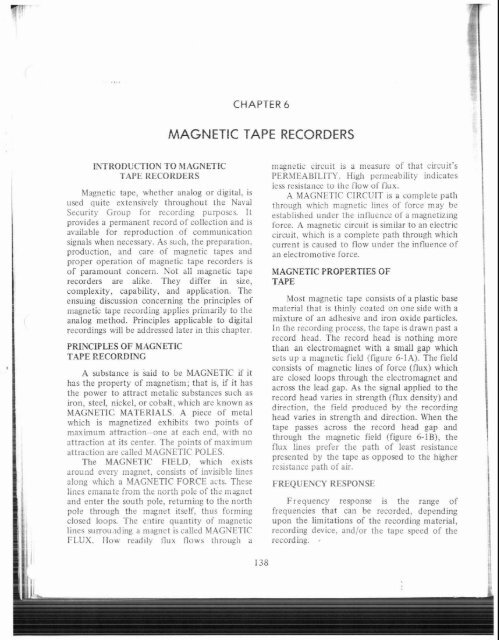
Most magnetic tape consists of a plastic base<br />
material that is thinly coated on one side with a<br />
mixture of an adhesive and iron oxide particles.<br />
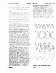
In the recording process, the tape is drawn past a<br />
record head. The record head is nothing more<br />
than an electromagnet with a small gap which<br />
sets up a magnetic field (rigure 6-1A). The field<br />
consists of magnetic lines of force (flux) which<br />
are closed loops through the electromagnet and<br />
across the lead gap. As the signal applied to the<br />
record head varies in strength (flux density) and<br />
direction, the field produced by the recording<br />
head varies in strength and direction. When the<br />
tape passes across the record head gap and<br />
through the magnetic field (figure 6-IB), the<br />
flux lines prefer the path of least resistance<br />
presented by the tape as opposed to the higher<br />
rcsistance path of air.<br />
along which a MIAGNETIC FORCE acts. These FREQUENCY RESPONSE<br />
lines emanate from the north polc of thi: inagnct<br />
and enter the south pole, returning to the north Frequency response is the range of<br />
pole through the magnet itself, thus forming frequencies that can be recorded, depending<br />
closed loops. The eiltire quantity of magnetic upon the limitations of the recording material,<br />
lines surrou.lding a magnet is called MAGUETIC recording device, and/or the tape speed of the<br />
FLUX. Ilow readily tlux tlows through a recording. ,<br />
3 . /<br />
2 . I<br />
~ . 138<br />
1,<br />
I;fi:1
i<br />
A. FIELD DISTRIBUTION AROUND THE GAP OF A<br />
RECORDING HEAD. IN AIR<br />
Chapter 6-<strong>MAGNETIC</strong> <strong>TAPE</strong> <strong>RECORDERS</strong><br />
critical as the reproduce gap since the signal is<br />
put on the tape by the record head trailing edge.<br />
If the recording head shown in figure 6-1 B had<br />
no air gap, the magnetic field set up around the<br />
electromagnet would be weak and would run in<br />
a direction 90 degrees to the field shown; that is,<br />
into and out of the paper. A magnetic field of<br />
this type would be of little use for magnetic<br />
recording. Therefore, an air gap is used to<br />
provide a suitable magnetic field. The smaller<br />
the air gap can be made, the better the<br />
high-frequency response improvement in this<br />
direction.<br />
Frequency-Tape Speed<br />
Relationship :<br />
Increasing the tape speed increases the<br />
length of tape passing the record head in a given<br />
period of time. It follows that for any given<br />
frequency, the distance between magnetic<br />
B. FIELD DISTRIBUTION AROUND THE GAP OF A<br />
RECORDING HEAD, DURING RECORDING<br />
patterns is directly dependent upon the speed at<br />
which the tape moves past the recording head.<br />
Therefore, if the frequency to be recorded<br />
increases beyond certain values, the tape speed<br />
must be increased to gain an accurate<br />
reproduction of that frequency. This<br />
1.245 requirement is met in present generation tape<br />
Figure 6-1.-Recording head magnetic field distribution. recorders by making more than one recording<br />
speed available to the operator. For example,<br />
some recorders presently in use in the Navy<br />
Recording Material<br />
record accurately frequencies up to<br />
approximately 100,000 hertz at a tape speed of<br />
The size of the adhesive/iron oxide particles 7% inches per :second. This cipability<br />
is one factor whch determines the frequency theoretically doubles as the speell of operation<br />
response that may be recorded. Each particle doubles. With present generation equipment it is<br />
acts like a small bar magnet, and the smaller the , possible to record 2 MHz at 120 inches per<br />
particle size; the higher the frequency response. second. In theoj, 'this is an endless progression;<br />
The small particle size not only makes the increase the tape speed and, the maximum<br />
recording of high frequencies possible, but also recordable frequency 'is increased. Mechanical<br />
makes it easier to obtaln a smooth surface, even considerations, however, limit the maximum<br />
,I<br />
particle distribution, and a constant thickness of tape speed that can be used ,and' the present<br />
coating. These factors are essential for the trend is toward using increasingly smaller gap<br />
production of a lugh quality recording<br />
widths and improved amplification circuitry to<br />
gain increased frequency response.<br />
Air Gap THE BASIC RECORDER<br />
The principal limitation in reproducing Magnetic recorders are not particularly !<br />
. .<br />
higher frequencies is the reproduce head gap complicated. As previously discussed, magnetic !<br />
width. The record head gap width is not as tape is drawn past a recording head. As it passes , ,<br />
! 1<br />
:,<br />
139 I :<br />
1 I<br />
i I<br />
! ,<br />
i /<br />
L
through the magnetic field set up by the<br />
recording head, the material on the tape<br />
becomes and remains magnetized. The amount<br />
of magnetization remaining in the material at<br />
each instant is governed by the magnetic<br />
properties of the tape and the strength of the<br />
magnetic field set up by the recording head. The<br />
magnetic field set up by the rrcording head is<br />
directly proportional to the signal being<br />
recorded. In reproduction, the magnetization<br />
which remains in the recording material induces<br />
corresponding voltages in the coil of the<br />
reproduce head. The voltage variations in the<br />
coils of the reproduce head ze amplifivd and<br />
the original signal is recovered. The recording<br />
and reproduce heads may bc incorporated into a i<br />
single unit.<br />
Basic components of magnetic recorders<br />
include a record head, a reproduce head, and an<br />
erase head. In addition there are other<br />
component parts such as a transport mechanism,<br />
spools or containers for the tape, a compensated<br />
record and playback amplifier, and special ffiter<br />
systems.<br />
MULTITRACK <strong>RECORDERS</strong><br />
The vast majority of magnetic tape recorders<br />
used in the Naval Security Group are multitrack<br />
recorders, i.e., 2, 7, 8, and 14 tracks. Multitrack<br />
recording is made possible by using more than<br />
one record head, one for each track. The record<br />
heads are placed side by side in what is called<br />
the "head stack". A laminated magnetic shield is<br />
used between each track to prevent interference.<br />
In effect, each record head acts as a separate<br />
recorder with its own amplifier circuits. Figure<br />
6-2 illustrates the head stack of a 4-track<br />
recorder.<br />
There are times when it is desirable to record<br />
two or more related signals simultaneously.<br />
Also, in some applications, it is desirable to<br />
record, in addition to the signal(s), Information<br />
such as voice annotations. standard time<br />
transmissions, or standard reference tone for<br />
tape speed check. The multitrack recorder<br />
makes possible such multiple recordings.<br />
Careful spacing of the record heads is<br />
necessary to minimize overlap or "crosstalk" in<br />
muitipie-track rrcnrdings.<br />
CRYPTOLOGIC COLLECTION EQUIPMENTS<br />
93.45<br />
Figure 6-2.-Four-track recorder head Rack.<br />
<strong>MAGNETIC</strong> <strong>TAPE</strong> ERASURE<br />
One advantage of magnetic recording tape is<br />
that recordings may be erased and the tapes<br />
reused a number of times. Magnetic tapes may<br />
be erased by a d.c. field and/or an a.c. field.<br />
D.C. Erasure<br />
Erasure can be accomplished by magnetizing<br />
the medium to saturation with a very strong d.c.<br />
field or with the field from a strong permanent<br />
magnet. However: this method is not<br />
satisfactory because such a field, while it<br />
obliterates the previously recorded signal, leaves<br />
the tape particles strongly magnetized in one<br />
direction and produces a large amount of noise<br />
and considerable distortion in the next<br />
recording.<br />
A.C. Erasure (Degaussing)<br />
A better erasure system is to demagnetize<br />
the tape by the use of an ax. field which drives<br />
the medium to saturation alternately in both<br />
directions and then gradually reduces to zero ir~<br />
the course of many alternations. This process is<br />
commonly known as "degaussing." In order to<br />
achieve many alternations in a small gap length,<br />
and to prevent any residual fields which will<br />
cause an audible note. the frequency of the<br />
erasing ccunent for audio type recorder% sho~lld
I<br />
be 3 to 5 times higher than the highest recorded<br />
frequency.<br />
To better understand the degaussing process,<br />
consider a single magnetized particle on the<br />
tape. During the degaussing process the<br />
magnetizing force of the erasing field brings the<br />
degree of magnetization of that particle first to<br />
saturation in one polarity and then to saturation<br />
in the opposite polarity. As the tape moves out<br />
of the erasing field and the influence of the<br />
erasing field and dies away gradually, the degree<br />
of magnetization of that particle continuoi~sly<br />
decreases in alternate polarities until a state of<br />
zero magnetization is achieved and erasure is<br />
complete.<br />
For erasure to achieve completc<br />
demagnetization, (1) the head milst be free of<br />
permanent magnetization. (2) there should be<br />
no d.c. field in the vicinity (such as from<br />
magnetized steel parts, meter movements, etc.),<br />
and (3) the waveform of the erase current must<br />
by symmetrical (equal positive and negative<br />
peaks).<br />
If the following procedures are observed,<br />
troubles caused by poor erasure should be<br />
greatly reduced:<br />
1. If recordings are not completely erased<br />
in one pass, repeat the erasure.<br />
2. Carefully monitor the recording level to<br />
avoid overdriving the signal, thereby causing a<br />
"memory effect" in which the recorded signal<br />
will return after erasure.<br />
I Automatic T ap Degaussers<br />
!<br />
f<br />
i<br />
Although tape erasure by the recorder is<br />
satisfactory for some applications, it requires the<br />
tape to be run through the recorder (as in<br />
recording) and is time consuming. In addition,<br />
most precision tape recorders designed for<br />
special applications do not have an erase<br />
capability. To erase magnetic tapes quickly and<br />
efficiently, an automatic tape degausser is<br />
available at most field stations.<br />
An automatic tape degausser (such as the<br />
one shown in figure 6-3) completely erases<br />
signals from magnetic tape by moving the whole<br />
7 reel of tape slowly and steadily into 2nd out of<br />
i an intense, alternating magnetic field while<br />
continuously rotating the reel. This subjects all<br />
portions of the tape to a thorough degaussing<br />
b<br />
Chapter 6-<strong>MAGNETIC</strong> <strong>TAPE</strong> RECORIlEI
F<br />
CRYPTOLOGIC COLLECTION EQUIPMENTS<br />
Figure 6-4.-ANITNH-11 tape recorder with applique unit.<br />
ANITNH-11 Accessory<br />
Units<br />
MICROP1IONE.-The microphone uses a<br />
pusll-to-talk switch which opens the micropho::~<br />
rircriit to the recorder.<br />
The AN/TNH-I I<br />
following units:<br />
accessories inc1t:de the<br />
FOOTSWITCH.-A three ~osition nedal<br />
~~-<br />
contra! which provides foot operarion in tk7.c<br />
REMOTE CONTROL UNIT.-This unit positions: first position-Reproduce mode,<br />
controls the tape in both the record and sccotid position-Stop mode. and third<br />
reprod1:cc ,xodc. position-RcwLzd ii~odc.<br />
. ~~<br />
7<br />
I
Chapter 6-<strong>MAGNETIC</strong> <strong>TAPE</strong> <strong>RECORDERS</strong><br />
Controls and Fu~lctions Tape Loading<br />
The controls and functions contained The ANITNII-I I tape loading procedures are<br />
in the applique unit are identical to listed in the following steps: (refer to figure 6-5)<br />
the controls contained in the main unit.<br />
Therefore, only the main unit controls 1. Load a 7-inch reel of tape on the supply<br />
and functions will be explained in table (left) spindle. (Several feet of tape should be<br />
6-1. allowed to hang from the supply wheel.)<br />
Table 6-1.-ANITNH-11 RecorderIReproducer Controls and Functions<br />
CONTROL FUNCTION<br />
POWER ON switch<br />
SPEED control<br />
RECORD switch<br />
PLAY switch<br />
FAST FORWARD switch<br />
STOP switch<br />
REWIND switch<br />
AMPLIFIER controls<br />
INPUT/OUTPUT switch<br />
DIGITAL COUNTER<br />
Supplies power to the main unit and applique unit when in<br />
the ON position. The power ON condition is indicated by the<br />
illumination of the yellow POWER indicator lamp.<br />
The SPEED control is graduated zero through ten with an<br />
extreme counter-clockwise OFF position. In PLAY MODE<br />
ONLY, the SPEED control may be utilized to vary the tape<br />
speed between plus 20 per cent and minus 30 per cent of the<br />
basic 3-314 ips obtained with the SPEED control in the OFF<br />
position.<br />
The momentary-press type RECORD switch is red and places<br />
the recorder in the record mode. Operation in the record<br />
mode is indicated by the illumination of the red RECORD<br />
indicator lamp.<br />
Selects the mode of operation for reproducing previously<br />
recorded tapes.<br />
Causes the tape to be wound on the take-up reel at an<br />
accelerated rate of approximately 250 ips.<br />
Stops the tape. When going from either REWIND or FAST<br />
FWD mode to PLAY, or RECORD, the STOP button must<br />
be depressed before the PLAY or RECORD button is<br />
selected.<br />
Causes the tape to be rewound onto the supply (take-up) reel.<br />
Four AMPLIFIER controls used to regulate the record or<br />
reproduce gains: RECORD GAIN, color-coded red; PLAY<br />
GAIN, color-coded green; MICROPHONE GAIN, color-coded<br />
blue; TONE CONTROL, color-coded black.<br />
Applies the input (record) signal to the VU meter in the<br />
INPUT position. Applies the playback (reproduce) signal to<br />
the VU meter in the OUTPUT position.<br />
Provides an arbitrary figure as a reference aid so the operator<br />
may return to certain locations on the tape.<br />
143
CRYPTOLOGIC COLLECTION EQUIPMENTS<br />
Fiqre S5.-ANITNH-11 tape threaditq.<br />
144<br />
7<br />
I
2. Close the supply reel retainer and lock<br />
the tape reel.<br />
3. Place an empty tape reel on the take-up<br />
spindle.<br />
4. Close the empty reel retainer and lock<br />
the tape reel.<br />
5. Thread the tape over the compliance<br />
arm, through the head cover slot, between the<br />
pressure roller and capstan, under the tape guide<br />
and onto the empty reel.<br />
After the tape has been loaded on the reel<br />
and across the head area, the counter should be<br />
set to zero. This is done by revolving the<br />
serrated wheel on the left side of the counter<br />
until a zero reading is obtained. If it is then<br />
required to find a certain spot on the tape at a<br />
later time, and if adequate notations have been<br />
made on the reel container. the counter will be<br />
found to be quite useful as'an approximation of<br />
a given portion of the recording.<br />
Operating Procedure<br />
The AN/TNH-11 can be used to record<br />
and/or reproduce previously recorded<br />
information. Each type of operation will be<br />
discussed briefly.<br />
RECORDING OPERATION.-Set the line<br />
input level. This is done by setting the<br />
INPUTIOUTPUT switch to INPUT and adjusting<br />
the RECORD GAIN so that peaks of the signal<br />
read approximately zero vu's on the VU meter.<br />
If a microphone iilput is also to be used, the<br />
MICROPHONE GAIN should also be set for a<br />
reading of zero vu's on the meter using the peaks<br />
of the individual's voice as a signal source.<br />
Depress the RECORD switch ' and begin<br />
recording. Depress the "push-to-talk" switch on<br />
the microphone to make overriding commentary<br />
announcements. When it is desired to end the<br />
recording, depress the STOP pushbutton.<br />
PLAYBACK OPERATION.-The PLAY<br />
pushbutton should be depressed and the<br />
PLAYBACK GAIN control adjusted so that the<br />
output is zero vu's or a comfortable listening<br />
level. The TONE control may be adjusted for a<br />
comfortable listening tone. When the TONE<br />
control is in the FLAT position, playback tone<br />
Chapter 6-<strong>MAGNETIC</strong> <strong>TAPE</strong> <strong>RECORDERS</strong><br />
is the same as the recorded tone. When operating<br />
in the PLAY mode the speed control can be<br />
used to vary the tape speed between plus 20 per<br />
cent and minus 30 per cent of the basic 3-314<br />
ips. This is to compensate for a recording made<br />
at a speed other than 3-314 ips or to vary the<br />
speed as an aid for transcription.<br />
NOTE: The magnetic heads must be cleaned<br />
after each 10-1 5 hours of operation. This is<br />
primarily the operator's responsibility. To clean<br />
the heads, moisten a clean cotton swab with the<br />
available head cleaner and gently wipe the heads<br />
to remove dirt and oxide accumulated from the<br />
tape.<br />
ANlGSH-19 SIGNAL DATA<br />
RECORDER/REPRODUCER<br />
The ANIGSH-19 (figure 6-6) is an<br />
eight-track analog recorder/reproducer that is<br />
primarily used to provide analog back-up<br />
recording of data being recorded in digital form<br />
on up to three AN/GSQ-76 positions (TEBO).<br />
The analog recording can be used for special<br />
analysis and high-speed processing when the<br />
digital recorder on the TEBO system fails to<br />
operate. It is also used to record signals that<br />
cannot be processed on the TEBO system. The<br />
AN/GSH-19 uses 112 inch magnetic tape on 10%<br />
inch tape reels (3600 ft.) and operates at one of<br />
three available tape speeds: 1-718, 3-314, and<br />
7-112 ips for a recording/reproduce time of 360,<br />
180, and 90 minutes, respectively.<br />
Components<br />
The AN/GSH-19 is contained within a single<br />
equipment bay and is comprised of:<br />
a. Tape Transport Units (upper and lower)<br />
which provide uniform tape tension and speed<br />
across the record and reproduce heads.<br />
b. Control/Indicator Assembly which<br />
contains all tape motion controls and the<br />
monitoring, both visual and aural, circuitry.<br />
c. Data Amplifiers (upper and lower) which<br />
contain the amplifiers for record and reproduce<br />
functions of the AN/GSH-19 for upper and<br />
lower tape transports.
CRYPTOLOGIC COLLECTION EQUIPMENTS<br />
264<br />
Figure 6-6.-AN!GSH-19 analog recorder.<br />
Functional Description<br />
The AN/GSH-19 has four (4) operating<br />
modes: RUN, RECORD, FORWARD, and<br />
RE WIND. Provision for automatic tape<br />
transport control is facilitated by three<br />
photo-conductive cells (tape sensing devices);<br />
the <strong>TAPE</strong> TENSION or PROGRAM scnsor, the<br />
<strong>TAPE</strong> BREAK sensor and the LOW <strong>TAPE</strong><br />
scnsor. Normal procedure is to record with one<br />
transport while the alternate transport is being<br />
reloaded. However, simultaneous transport<br />
operation is possible. Sequential operation of<br />
transports is madc possible by the LOW <strong>TAPE</strong><br />
I .<br />
bClii-ii ilii- tape reachcs a point 0:: the<br />
supply reel where there is approximately three<br />
minutes left, tlie photoconductive cell is allowed<br />
to complctc its circuit and therehy starts the<br />
next transport. providing the overlap.<br />
Controls and Functions<br />
All controls nceded for operation of the<br />
AN/GSH-I9 are located on the<br />
Control/Indicator Assembly panel (figure 6-7).<br />
Separate controls are used for operation of<br />
either tape transport. Oscilloscopes and controls<br />
for visual and aural monitoring are available for<br />
checking the input and recorded signals.<br />
Controls/lndicators and their functions are listed<br />
in table 6-2.<br />
Operating Procedures<br />
The following operating procedures should<br />
bc ~lsed when operating the AN/GSH-I 9.<br />
<strong>TAPE</strong> SELECTION.-Prior to operation of<br />
tlie AN/GSH-19, ensure that the following has<br />
hccn accomplished:<br />
a. Analog niagnctic tapc has been sclected<br />
(analog tapes have aluminum reels while digital<br />
tapes used with TEBO positions arc plastic with<br />
grccn flanges).<br />
b. Analog tape rccl is not warped or<br />
otherwise damaged.<br />
c. Magnetic tape is sniootlily wound on the<br />
tapc rcpl 2nd contains no "hunched up" areas.
I 264.86<br />
Chaptcr 6-MAGN1:TIC <strong>TAPE</strong> <strong>RECORDERS</strong><br />
Figure 6-7.-ANIGSH-I9 controllindicator assembly panel.<br />
Table 6-2.-ANIGSH-19 Controls/lndicators and Functions<br />
I CONTROLS/INDICATORS FUNCTIONS<br />
I POWER pushbutton Controls the a.c. input to components of the AN/GSH-I 9.<br />
LOCAL/SEQUENTIAL pushbutton ,411 alteriiate action pushbutton that selects the desired<br />
mode of operation. This pushbutton is depressed and<br />
rolcased until the appropriate portion, LOCAL or<br />
SEQUENTIAL, of the control lights up.<br />
RUN pushbutton<br />
RECORD pushbutton<br />
LOCAL mode - Provides independent operation<br />
of each tape transport. The<br />
LOCAL mode will be used for all<br />
recording/reproducing.<br />
SEQUENTIAL mode - This mode providesfor continuous<br />
running from one transport to the<br />
other. SEQUENTIAL mode will<br />
NOT be used by the operator.<br />
Energizes the selected transport at the speed selected by<br />
the <strong>TAPE</strong>-SPEED selector.<br />
Applies record current to the record head. It must be ac-<br />
tivated before the RUN pushbutton is depressed to record.<br />
: I<br />
, ,<br />
I !<br />
~<br />
I
I<br />
I<br />
CRYPTOLOGIC COLLECTION EQUIPMENTS<br />
Table 6-2.-ANIGSH-19 Controlsllndicators and Functions-Continued<br />
CONTROLS/INDICATORS FUNCTIONS ! I<br />
REWIND pushbutton Provides high-speed transfer of tape from the take-up reel /<br />
to the supply reel. This control will operate in the LOCAL I<br />
mode only. I<br />
FORWARD pushbutton Provides high-speed transfer of the tape from the supply<br />
reel to the take-up reel. This control will operate in the<br />
LOCAL mode only.<br />
STOP piishbii::on Stops the trzcsp~lrt.<br />
GAIN control<br />
Controls the amplitude of the reproduced signal on the<br />
reproduce oscilloscope. The GAIN control also controls<br />
the volume of the AUDIO MONITOR jack.<br />
I <strong>TAPE</strong>-SPEED selector Selects the tape speed in inches per second.<br />
SWEEP controls (2) These are five-position rotary controls that select one of<br />
five sweep rates for oscilloscopes. The SWEEP controls<br />
have no effect on the recording.<br />
I<br />
!<br />
CHANNEL SELECTOR switch This is an eight-position rotary switch that selects the<br />
Individual cnannel (track) to be monitored on the<br />
oscilloscope and at the AUDIO MONITOR jack.<br />
i<br />
I<br />
i t<br />
RECORD/REPRODUCE switch This is a two-position toggle switch that connects either<br />
the input signal to be recorded or the reproduced signal<br />
to the headset jack (AUDIO MONITOR).<br />
i<br />
1 i<br />
b<br />
RECORD OSCILLOSCOPE Displays the input signal.<br />
b I<br />
REPRODUCE OSCILLOSCOPE Displays the reproduced signal.<br />
AUDIO MONITOR Headset jack. The signal heard via the monitor will depend<br />
upon the position of the CHANNEL SELECTOR switch.<br />
Volume of the signal heard is controlled by the GAIN<br />
control.<br />
<strong>TAPE</strong> LOADING.-(refer to figure 6-8).<br />
! a. Insert a reel of tape on the upper (supply)<br />
1 reel hub and seat it firmly against the hub. Lock<br />
the reel hub by exerting pressure against the<br />
center of the lock, pushing in.<br />
b. Install an empty reel on the lower<br />
, , (take-up) tee! h?ub using the same procedures for<br />
i 1 loclang as in step a.<br />
c. Rotate the supply reel counterclockwise<br />
to release about four feet of tape for threading.<br />
d. Thread the loose tape over the :<br />
upper-guide roller, through the upper guide, i<br />
between the upper capstan and pressure roller, i<br />
over the record and reproduce heads, between :<br />
the lower capstan and pressure roller, through<br />
the lower guide. over the lower guide rolier to ..<br />
.1~ - 1.1.- _. -1<br />
LUG ~at.c-up AGGL.<br />
I<br />
1<br />
I<br />
I<br />
i<br />
6<br />
i :<br />
;<br />
i
SUPPLY REEL<br />
Chapter 6-<strong>MAGNETIC</strong> <strong>TAPE</strong> <strong>RECORDERS</strong><br />
LOWER CAPSTAN<br />
LOWER GUlDE<br />
transport will stop automatically at the end of<br />
the reel.)<br />
FORWARD MODE.-If reproduce is desired<br />
from the tape at some distance from the<br />
beginning, the forward mode provides fast drive<br />
to that point as follows:<br />
(1) Press the FORWARD selector. The<br />
FORWARD selector illuminates, and the<br />
transport moves the tape in the forward<br />
direction at a fast rate. The pressure rollers are<br />
not engaged, and no usable information is<br />
reproduced.<br />
(2) When the desired point on the tape is<br />
reached, press the STOP selector. If the<br />
reproduce mode is desired at this point, press<br />
RUN as previously described.<br />
REWIND MODE.-When the end of the run<br />
or record program is reached, the tape may be<br />
rapidly transferred back to the supply reel as<br />
follows:<br />
264.87<br />
(1) Press the REWIND selector. The tape<br />
moves in the reverse direction at a fast rate. The<br />
REWIND selector illuminates.<br />
Figure 68.-ANIGSH-19 tape loading.<br />
e. Hold the end of the tape to the take-up<br />
(2) If stop is desired before the tape runs<br />
completely off the take-up reel, press the STOP<br />
selector.<br />
reel and rotate the reel counterclockwise until RECORD MODE.-With a freshly degaussed,<br />
the tape is secured to the take-up reel. clean reel of tape loaded on the supply reel hub,<br />
RUN MODE.-The an mode is used for<br />
establish the record mode as follows:<br />
reproducing a prerecorded tape as fouows: (1) Press and hold the RECORD selector,<br />
With a prerecorded tape loaded On the<br />
press the RUN The<br />
move tape in the forward<br />
direction with the pressure roUers engaged. The<br />
RUN selector should illuminate.<br />
then press the RUN selector. (If the RUN<br />
selector is pressed before the RECORD selector,<br />
the record mode will not engage.) The tape will<br />
run forward at the selected speed with the<br />
pressure rollers engaged, The RECORD and<br />
RUN selectors should illuminate.<br />
NOTE: A reproduce amplifier plug-in circuit<br />
card must be installed in the Upper or Lower<br />
Data Amplifier asseniblies in order toreproduce<br />
a prerecorded tape. One plug-in circuit card is<br />
NOTE: The Record plug-in circuit cards<br />
have to be installed in the Data Amplifier<br />
Assemblies for each individual track being<br />
needed for each individual track being recorded.<br />
reproduced.<br />
(2) The record mode may be cancelled by<br />
(2) If a stop conclition is desired on the pressing any transport control selector<br />
transport, press the STOP selector. (The (FORWARD, REWIND, or STOP).
I<br />
1<br />
CRYPTOLOCIC COLLECTION EQUlPiMENTS<br />
NOTE: Any time thc microphone (4)Thi: data signals may be aurally<br />
press-to-talk switch is pressed during the record ~nonitored by connecting a headset to the<br />
mode, the channel I data signal is interrupted. AU D 10 MONITOR and setting the<br />
To insure that this does not occur, remove the RECORD-REPRODUCE szlector to the desired<br />
microphone plug from the control-indicator position.<br />
panel microphone connector immediately after<br />
use. ANIUNQ-7E I<br />
RECORDER-REPRODUCER<br />
LOCAL MOD!
Chapter 6-<strong>MAGNETIC</strong> TAI'E RtC'OKDERS<br />
Figure 6-9.-ANIUNQ-7E recorder/reproducer.<br />
151
Figure 610.-ANIUNCk7E remote control unit.<br />
CRYPTOLOGIC COLLECTION EQUIPMENTS I I<br />
264.89<br />
(3) Install a full reel of tape on the supply<br />
turntab!e of tape transports 1 and 2. Place an<br />
empty reel on each take-up turntable. Thread<br />
the tape from the supply reel, through the tape<br />
head and onto the take-up reel (as illustrated on<br />
the front of the transport). Perform this<br />
operation on both transports.<br />
(4) Set both tape counters to 000.<br />
(5) Set speed selector on tape transports to<br />
the desired speed.<br />
(6) Adjust signal input level (minus three to<br />
zero) by observing the appropriate VU meter.<br />
Operating Procedures<br />
Perform the following steps in operating the<br />
AN/UNQ-7E (transport 1):<br />
1. Actuate both RECORD switches<br />
momentarily to position I, simultaneously.<br />
Observe that the tape begins moving forward at<br />
the required speed, and that the RECORD I red<br />
lamp illuminates.<br />
2. Press the STOP button on Tape<br />
- lransport<br />
_ 1. Observc :hat the tape stops movL!g<br />
;nd :kt :he ?.ElcrO?.T! !.rm: r.xtl!!g?!iche~<br />
3. Momentarily actuate the REPRODUCE<br />
switch to position 1. Observe that the tape<br />
moves forward at the required speed, and that<br />
the Reproduce 1 green lamp illuminates.<br />
4. Press the STOP button on Tape<br />
Transport 1. Observe that the tape stops and<br />
that the Reproduce lamp extinguishes.<br />
5. Actuate the FAST FWD - REWIND<br />
toggle switch momentarily to the FAST FWD<br />
position. Observe that the tape moves rapidly<br />
from the supply reel to the takeup reel. Allow<br />
FAST FWD operation until the supply reel is<br />
very close to being empty before stopping the<br />
rranspori. Observe that th? STANESY ! amber<br />
lamp at the Remote Control Unit (RCU) is<br />
flashing, denoting end of tape.<br />
6. Reactuate the switch to the FAST FWD<br />
position and observe that the flashing amber<br />
light extinguishes and that both reels stop<br />
immediately after tape comes off the supply<br />
reel.<br />
7. Thread the loose end of the tape across<br />
the heads and back onto the supply reel.<br />
1<br />
8. Actuate the FAST FWD-REWIND<br />
switch momentarily to the REWIND position.<br />
Observe that the tape moves rapidly from the<br />
take-up to the supply reel. Stop the transport<br />
before full rewind so that the tape remains<br />
threaded.<br />
i<br />
9. At the RCU (Remote Control Unit)<br />
observe that both STANDBY amber lamps are<br />
i !<br />
i<br />
illuminated, then initiate RECORD at the RCU<br />
by actuating the TRANSPORT SELECT switch<br />
to 1 and the RECORD-STANDBY switch to<br />
RECORD. Observe that STANDBY 1 amber<br />
i<br />
lamp extinguishes and that the RECORD 1 red<br />
lamp illuminates.<br />
10. Return the RECORD-STANDBY switch t i<br />
to STANDBY and the TRANSPORT SELECT I<br />
switch to the center position. Observe that the<br />
STANDBY 1 lamp illuminates and the<br />
RECORD lamp extinguishes. I<br />
NOTE: Perform the above seque:ice of steps<br />
on Tape Transport 2. L<br />
AN/TNH-20 (V)<br />
RECORDER-REPRODUCER<br />
The AN/TNH-20(V) (figure 6-1 1) is a<br />
transistorized, three-speed: four-channel<br />
magnetic tape recorder-reproducer sel capabic uf :<br />
I<br />
i
CONTROLSIINDICATORS<br />
Chapter 6-<strong>MAGNETIC</strong> <strong>TAPE</strong> <strong>RECORDERS</strong><br />
Table 6-3.-ANIUNQ-7E Operating Controls. Indicators, and Functions<br />
FUNCTION<br />
Power Switch Controls Power to Recorder-Reproducer ON or OFF<br />
Power Indicator Lamp Indicates when power is applied to equipment<br />
Tape Speed (1 on each Selects either 3.75, 7.5 or 15 ips.<br />
tape transport)<br />
Stop Button (1 on each Stops tape.<br />
tape transport)<br />
NOTE<br />
Stop button must be activated before change of<br />
operational mode.<br />
Fast FWD-REW switch Initiates Fast Forward and Rewind<br />
(1 on each tape transport)<br />
Tape Counter (1 on each Counts from zero to indicate tape usage<br />
tape transport)<br />
Record switch (2) Initiates Record function on tape transport 1<br />
or 2, when actuated simultaneously.<br />
Record lights 12) Indicates when tape transport 1 or 2 is in Record<br />
mode.<br />
Reproduce switch Initiates Reproduce function on tape transport<br />
1 or 2.<br />
Reproduce lights (21 Indicates when tape transport 1 or 2 is in<br />
Reproduce mode.<br />
Channel A Record Level Controls Channel A record Signal level.<br />
Control<br />
Channel B Record Level Controls Channel B record Signal level.<br />
Control<br />
NORMAL POSITION OR<br />
INDICATION<br />
Illuminated white when power is<br />
ON<br />
As desired<br />
Momentarily depressed<br />
Center OFF<br />
Setting of 000<br />
Center OFF position<br />
Illuminates red during Record<br />
function<br />
Center OFF<br />
Illuminates green during<br />
Reproduce function.<br />
Not applicable<br />
Not applicable<br />
Record Level VU Meters (2) lndicates level of record signal. Proportional to signal<br />
Channel A output Level Controls level of output signal in Reproduce<br />
Control mode.<br />
Channel B output Level Controls level of output signal in Reproduce<br />
Control mode.<br />
Channel A and B output Provides for audio output monitor.<br />
jacks<br />
Not applicable<br />
Not applicable<br />
Not applicable
ji<br />
!:<br />
CRYPTOLOGIC COLLECTION EQUIPMENTS<br />
Table 6-4.-ANIUNQ-7E Remote Control Unit Controls, Indicators, and Functions<br />
\: cONTROLS/INOICATORS FUNCTION NORMAL POSITION OR<br />
INDICATION<br />
Transport Selector Switch Locks out local control of transport 1 or 2 and Center off<br />
prepares transport for record function.<br />
Record-Standby Switch Initiates Record function on transport selected Standby<br />
by Transport Selector switch.<br />
Standby 1 lamp lndicates Tape Transport 1 is in Standby mode,<br />
or nearing end of tape.<br />
Illuminates steady amber when<br />
in standby and flashes when<br />
near end of tape.<br />
c... .,,. . ,--"<br />
~ L ~ # ~ UL Vaom~p Y<br />
Same as ahnvp fnr Tanr Transport 2. Same as above<br />
Record Level VU meter<br />
Channel A or B Selector<br />
Switch<br />
Indicates level of record signal for either tape<br />
transport selectively.<br />
Proportional to signal<br />
Selects cha:>;~el to he monitor~rl hy VU meter. At either A or B<br />
Record 1 lamp Indicates when Tape Transport 1 is in Record mode, Illuminates red I<br />
Record 2 lamp Indicates when Tape Transport 2 is in Record mode. Illuminates red<br />
Figure 611.-AN/ I NH-Zuivj recoraerireproriucrr.<br />
154<br />
!
i<br />
1<br />
Chapter 6-<strong>MAGNETIC</strong> <strong>TAPE</strong> <strong>RECORDERS</strong><br />
recording and reproducing audio frequency the unit is equipped with an automatic stop<br />
signals. It is designed to perform dependably in which ceases the operation if a tape is broke,! or<br />
fixed stations and in mobile units. The at the end of a reel.<br />
equipment uses standard 114-inch tape on reels<br />
up to seven inches in diameter and operates at Operator Controls, Indicators<br />
speeds of 1-718, 3-314, and 7% (ips). The 1-718 and Functions<br />
Table 6-5.-AN/TNH-ZO(VI Operating Controls. Indicators, and Functions<br />
CONTROLIINDICATOR FUNCTION<br />
POWER ON switch Controls power to Recorder-Reproducer<br />
POWER Indicator Lamp Indicates when power is applied to equipment<br />
Tape SPEED SELECTOR Selects either 1-718 variable, 1-7/8,3-314, or 7-112 ips<br />
Variable SPEED Control Selects percent above or below 1-718 ips tape speed<br />
- 30% + 50% in Reproduce mode only.<br />
RECORD pushbutton Initiates Record function<br />
RECORD Lamp Indicates when tape transport is in the Record mode<br />
REPRO pushbutton Initiates Reproduce function<br />
FAST FWD pushbutton Initiates Fast Forward function<br />
STOP pushbutton Stops tape<br />
REWIND pushbutton Initiates Rewind function<br />
CHANNEL SELECTOR switch Selects channel to be monitored by VU meter<br />
INPUT/OUTPUT switch Selects either Record Input or Reproduce Output<br />
to VU meter<br />
I W meter Indicates level of Record and Reproduce signals<br />
Channel MONITOR Selects Reproduce channels to be monitored at<br />
headphone jacks and monitor output<br />
Adjusts frequency response at headphones and<br />
monitor output<br />
VOLUME control Adjusts volume at headphones and monitor output<br />
Digital Counter Counts from zero to indicate tape usage<br />
155
7.-'<br />
CRYPTOLOGIC COLLECTION EQUIPMENTS<br />
Operating Procedures <strong>TAPE</strong> LOADING.-The procedures for<br />
loading a tape on the ANITNH-20(V) are listed<br />
in the steps below:<br />
All four channels are data channels with<br />
i r. d<br />
provisions for automatic gain control (AGC) and<br />
voicc operated relay (VOR) operation. VOR<br />
allows for thc simultaneous recording of data<br />
and voice comments in the same channzl.<br />
Channel 4 is also a voice channel used for voice<br />
"dubbing." Record levels arc indicated by the<br />
VU nleter and automatically controlled when<br />
the AGCiDEE'EAT switch (located on the rear<br />
pan?!) iq in thc AGC: position. In the DEFEAT<br />
position, record levels are controlled by the REC<br />
GAIN control located on the RCDRIRPDR on<br />
the rear pancl. If VOR is not desired: the<br />
1. Install a full reel of recording tape onto<br />
the supply reel.<br />
2. Place an empty reel on the take-up reel.<br />
3. Thrcad the tape from the n~pply reel,<br />
across the tape heads. and onto the take-up reel<br />
(see figure 6-1 2).<br />
RECORDING.-The procedures for making<br />
a recording on the AN/TNH-2O(V) are listed in<br />
the steps below:<br />
1. Set the tape counter to 000 and select<br />
1<br />
i<br />
j j<br />
I<br />
i<br />
,<br />
VOK/UEFEAT switch (located on thc rsar<br />
panel) should be set in the DEFEAT position.<br />
Tape loading, record, and reproduce operating<br />
instn~ctions are described below for both AGC<br />
and VOR operation.<br />
tl~c desired tapc spccd.<br />
2. Depress the RECORD pushbutton and<br />
observe that the RECORD red lamp illuminates.<br />
3. Verify that the input signal is being<br />
properly recorded by either observing the<br />
1<br />
I<br />
1<br />
,I<br />
!<br />
H<br />
k4<br />
3<br />
5,<br />
r:-..-- c 3- nt.irrniu.rntv~ t.lDP loadina.<br />
1 .,<br />
'&. -.", .. .<br />
156<br />
264.91<br />
1
Chapter 6-<strong>MAGNETIC</strong> <strong>TAPE</strong> <strong>RECORDERS</strong><br />
reproduce output on the VU meter or by Tape Threading and Reel<br />
aurally monitoring the output signal with Installation<br />
headphones.<br />
4. To stop the recorder, depress the STOP Follow the steps listed below for tape<br />
pushbutton. (The FAST FWD and REWIND threading and reel installation: (Refer to figure<br />
pushbuttons may be depressed for fast 6-14). Either plastic or metal 4, 7, or 10% inch<br />
forwarding or rewinding the tape, respectively. reels, may he used.<br />
REPRODUCE.-The procedures for<br />
reproducing a recording on the AN/TNH-2O(V)<br />
are listed in the steps below:<br />
1. After properly positioning the tape,<br />
depress the REPRO pushbutton.<br />
2. Select the desired channel to be<br />
monitored at the headphone jacks by using the<br />
appropriate channel MONITOR control switch.<br />
3. The volume at the headphones can be<br />
adjusted by adjusting the VOLUME control to<br />
the desired level.<br />
4. The signal tone can be adjusted by<br />
adjusting the TONE control to the desired level.<br />
The AN/TNH-21 (figure 6-13) is a four<br />
track, solid state, magnetic tape<br />
recorder/reproducer. It uses %-inch magnetic<br />
tape, and 4, 7, or 10% inch reels and operates at<br />
five speeds: 15/16, 1-718, 3-314, 7-112, and 15<br />
inches per second (ips). It also has a variable<br />
tape speed in the play mode of +50 to -30<br />
percent. In addition to the usual tape recorder<br />
modes of play, record, stop, rewind, and fast<br />
forward, the AN/TNH-21 has two special modes;<br />
a variable search mode, and a repeat mode that<br />
allows for continued repetition of up to ten (10)<br />
seconds of tape in the reproduce mode. A<br />
remote control unit allows for the seven<br />
operating modes to be remotely controlled.<br />
NOTE: Tlie power may be ON or OFF when<br />
installing 3 reel and threading the tape.<br />
I. If plastic reels are being used, remove the<br />
hub assembly from the reel spinde. Pull out on<br />
the knurled end of the reel spindle and rotate to<br />
remove the reel retaining detents. If metal reels<br />
are being used, insure that the metal reel hub<br />
assemblies are installed and that the guide and<br />
reel retaining tabs are aligned.<br />
2. Place a full reel of tape on the supply<br />
reel side so that the tape unwinds from the left<br />
side of the reel. When installing plastic reels,<br />
place the reel onto the reel spindle and then<br />
secure by rotating the knurled end of the reel<br />
spindle to release the reel retaining detents.<br />
When installing a metal reel, place the reel on<br />
the hub assembly, and while holding the reel in<br />
place, pull out on the hub assembly and rotate<br />
60 degrees in either direction to the detents.<br />
3. Install an empty reel on the take-up reel<br />
spindle following the procedure in Step 2 above.<br />
4. Slide the lower head cover down to the<br />
thread tape position.<br />
5. Unwind about 4 feet of tape and thread<br />
the tape as shown in figure 6-14. Take a couple<br />
of turns around the take-up reel and turn the<br />
reel until there is tape tension.<br />
6. Slide the head cover up to the operate<br />
position.<br />
7. Set the REEL SIZE switch to the<br />
position corresponding to the reel size installed.<br />
8. Set the reel revolution counter to 0000<br />
by pressing the reset button.<br />
Operating Procedures<br />
Operating Controls, Indicators, There are seven modes of operation,<br />
and Functions<br />
including stand-by (STOP). All are selected by<br />
the mode control button/indicator on the front<br />
The ANITNH-21 operating controls, panel. Any mode may be selected while the<br />
indicators, and functions are described and recorder/reproducer is in any other mode. The<br />
explained in table 6-6. (Refer to figure 6-13). button/indicators light to indicate the mode the
CRYI'TOLOCIC COLLECTION EQUIPMENTS<br />
recorder is in. hch lnodc oi ui,cl-,itiotl is<br />
explained below.<br />
STANDBY mode must be selected before any<br />
other mode can be initiated. The STANDBY<br />
[node must be achieved as follows:<br />
STANDBY (STOP) MODE. -Wlie~i power is<br />
first applied, or when the tap< p3th has been I. Install and thread a reel of tape, if<br />
broken, i.e., when a new tape is tilt-cadetl. the needed.<br />
Figure 6-1 3.-ANjiNH-2i recorder/repioducer.<br />
158<br />
I<br />
!
Chapter 6-<strong>MAGNETIC</strong> <strong>TAPE</strong> <strong>RECORDERS</strong><br />
Table 66.-ANITNH-21 Operating Controls. Indicators, and Functions<br />
CONTROL OR INDICATOR FUNCTION<br />
POWER Switch/Indicator Control primary ax. power: push ON - push OFF.<br />
<strong>TAPE</strong> SPEED switch<br />
REEL SIZE switch<br />
TAKE-UP REEL COUNTER<br />
SCAN SEGMENT Control<br />
REPEAT switch/indicator<br />
PLAY switch/indicator<br />
Select one of the five standard, fixed, playlrecord tape<br />
speeds: 15/16, 1 718, 3 314, 7 112, or 15 ips.<br />
Changes the reel motor torque to compensate fox<br />
different reel size.<br />
Four digit counter that counts take-up reel rotation.<br />
The counter can be reset manually by pressing the<br />
adjacent button, or is automatically reset at the<br />
end-of-tape, when the recorder is in the rewind mode<br />
The SCAN SEGMENT controls are operative only<br />
when the recorder/reproducer is in the repeat mode.<br />
They adjust the length of the repeat scan segment<br />
from at least 10 seconds of tape to near zero. The<br />
BEGIN control (outer knob) adjusts the point where<br />
the play segment begins. The END control (inner<br />
knob) adjusts the end of the play segment.<br />
When the REPEAT button is pressed, the recorder<br />
will repeat a segment of tape from near zero to at<br />
least 10 seconds in length, or as determined by the<br />
SCAN SEGMENT control.<br />
When the PLAY button is pressed, the recorder will<br />
go into the play mode and reproduce the data<br />
recorded on the tape at the selected tape speed.<br />
STOP switch/STAND-BY indicator Stops tape motion, and initiates the standby mode.<br />
Any mode of operation can be initiated when the<br />
STOP button/indicator is lit. When power is first<br />
applied or when the tape path has been broken, i.e.,<br />
when a new tape is threaded, the STOP button must<br />
be pressed to initiate standby before any other mode<br />
can be initiated.<br />
RECORD switch/indicator<br />
REWIND switch/indicator<br />
The RECORD button activates the record electronics<br />
(including erase electronics) when pressed<br />
simultaneously with the PLAY button.<br />
Initiates the rewind mode when pressed. When<br />
stopping from any forward mode the recorder will<br />
momentarily go into the rewind mode for braking.
CRYPTOLOGIC COLLECTION EQUIPMENTS<br />
Table 6-6.-ANITNH-21 Operating Controls, Indicators, and Functions-Continued 1<br />
CONTROL OR INDICATOR FUNCTION<br />
FWD switch/indicator<br />
SEARCH switch/indicator<br />
SRCH SPEED controi<br />
SPEED VERNIER control<br />
RECORD LEVEL control<br />
SIGNAL LEVEL meter<br />
REClREP METER switch<br />
When the FORWARD button is pressed the recorder<br />
eoes into the fast forward mode.<br />
-<br />
The SEARCH buttonjindicator initiates and indicates<br />
the variable speed search mode. The tape moves<br />
forward at a speed determined by the setting of the<br />
SRCH SPEED control.<br />
7,--: " 6L- +,. vdie~ spced fro= 3.5 to 60 ips whtn the<br />
recorderlreproducer is in the search mode.<br />
Varies the tape speed between -30 and +SO percent of<br />
that selected by the SPEED switch. With the SPEED<br />
VERNIER in the OFF position, the selected tape<br />
speed is maintained.<br />
NOTE: The SPEED VERNIER is NOT operable<br />
in the record mode.<br />
Adjusts the input signal record level.<br />
Indicates the record and reproduce output signal<br />
levels.<br />
Selects the signal monitored by the meter: REC for<br />
record input level; REP for the reproduce output<br />
level.<br />
REPRO LEVEL control Adjusts the output level of the reproduced signal.<br />
VOLUME control<br />
TONE control<br />
Controls the volume for the monitor PHONES jacks<br />
(3).<br />
Controls the tone for the monitor PHONES jacks.<br />
In the OFF position, the monitor has a flat frequency<br />
response, B is for bass tone, and T is for treble tone.<br />
RECORD/REPRODUCE MONITOR Selects the signal(s) to be monitored at the PHONES<br />
switch jacks. RECORD for signal being recorded,<br />
REPRODUCE for reproduce output monitoring.<br />
Any combination of record and reproduce may be<br />
monitored.<br />
PHONES Phone jacks for three earphones.
Chapter 6-<strong>MAGNETIC</strong> <strong>TAPE</strong> <strong>RECORDERS</strong><br />
264.93<br />
Figure 614.-ANITNH-21 tape loading.<br />
2. Press the POWER switch and then the<br />
STOP button. The POWER and STOP (Standby)<br />
indicator should light.<br />
FAST FORWARD (FWD) MODE.-The Fast<br />
Forward Mode moves the tape rapidly from the<br />
supply reel to the take-up reel. It can be selected<br />
at any time by pressing the FWD<br />
button/indicator, and removed by selecting any<br />
other mode. If the fast forward mode continues<br />
until the tape runs out, the recorder/reproducer<br />
will stop automatically. A tape must be<br />
rethreaded and the standby mode must be<br />
reestablished before another mode can be<br />
selected.<br />
REWIND MODE.-The Rewind Mode<br />
operates the same as the fast forward (FWD)<br />
mode except it moves the tape from the take-up<br />
reel to the supply reel. If the tape runs out in<br />
the rewind mode, the reel revolution counter<br />
will automatically reset to 0000.<br />
PLAY MODE.-The Play Mode reproduces<br />
recorded tapes. The reproduced signals may be<br />
monitored at the monitor PHONE Jacks on the<br />
front of the recorder. The tape speed is<br />
controlled by the capstan and determined by<br />
setting of the SPEED Switch. The taoe s~eed<br />
may be varied +50 to -30 percent by the SPEED<br />
VERNIER control. To reproduce a recorded<br />
tape, proceed as follows:<br />
1. Thread the tape to be reproduced on the<br />
recorder and obtain the Standby Mode as<br />
previously described.<br />
2. Set the SPEED switch to the tape speed<br />
at which the reel of tape was recorded.<br />
3. Press the PLAY button/indicator. Tape<br />
monitor should start and the PLAY<br />
buttonlindicator should light.<br />
4. Place the METER switch of each channel<br />
to the REP position.<br />
5. Adjust the REPRO LEVEL control of<br />
each channel for the desired reproduce signal<br />
Aevel.<br />
6. The play mode may be cancelled at any<br />
time by se~eitiig any other mode<br />
RECORD MODE.-Follow the procedures<br />
listed below when operating in the Record<br />
Mode.<br />
1. Install a reel of tape and thread and<br />
obtain the standby mode as previously<br />
described.<br />
2. Set the SPEED switch to the desired<br />
tape speed.<br />
3. Place the METER switch of each channel<br />
to the REC position.<br />
4. Adjust the RECORD LEVEL control of<br />
each channel for over reading on the signal<br />
peaks, or for the maximum anticipated input.<br />
5. Simultaneously, press the PLAY and<br />
RECORD buttons. Both button/indicators<br />
should light and the tape will begin moving<br />
under the capstan control at the selected speed.<br />
NOTE: When recording, either the record<br />
and/or reproduce signals may be monitored.<br />
Monitoring the reproduce signal may be more<br />
meaningful because it is a reproduction of the<br />
signal being recorded.<br />
6. The Record Mode may be cancelled at<br />
any time by selecting any other mode.<br />
SEARCH MODE.-The Search Mode is a<br />
variable speed, forward mode for searching a
CRYPTOLOGIC COLLECTION EQUIPMENTS<br />
recorded reel of tape to locate data. In the REPEAT button/indicator at the point where<br />
search mode, the tape speed is adjustable by the the scan segment is to end. The REPEAT<br />
SEARCH SPEED Control from 3.5 ips to 60 ips. button/indicator will light and the tape will<br />
The monitor electronics are active in the search backspace the length of the scan segment and go<br />
mode which are inactive during the fast forward into the play mode.<br />
(FWD) mode. The search mode is normally used<br />
when an analog time signal has been recorded on NOTE: The SCAN SEGMENT controls may<br />
the tape. Data is located 011 the tape by knowing be set to any position; however, a setting<br />
the approximate time that the data was recorded midway between the maximum and minimum<br />
and by monitoring the play-back time readout. scan length in most cases will provide the best<br />
To operate the search mode, proceed as follows: results since this will allow adjustment of both<br />
ends of the scan segment in both directions<br />
1. Thread the tape and obtain the standby when the repeat mode is selected. The Capstan<br />
mode as previously described. SPEED VERNIER Control may be used in the<br />
2. Set the SEARCH SPEED control to any repeat mode as in the play mode. It will vary the<br />
desired position. tape play speed to +SO to -30 percent. This will<br />
3. Press the SEARCH button. The affect the time it takes to scan the segment of<br />
button/indicator should light and tape tape, but the length of tape will remain the same<br />
movement begins. (determined by the SCAN SEGMENT controls).<br />
NOTE: If the reel revolution counter is<br />
being used to locate a portion of the tape. press<br />
the FWD button and then the SEARCH button<br />
4. The repeat mode will continue until<br />
canceled by selecting another mode.<br />
as the counter approaches the desired reading.<br />
MONITORING.-The normal signal input<br />
4. The Search mode may be canceled by and output signals may be monitored from the<br />
selecting any other mode, or the search mode front of the recorder by up to three headsets.<br />
will continue until the tane runs out. None of the monitor functions have anv effect<br />
on the recorder/reproducer input or output<br />
REPEAT Iepeat<br />
continuously repeats a segment of tape from at<br />
least 10 seconds to near zero in length. Both the<br />
beginning and end of the scan segment are<br />
adjustable by the SCAN SEGMENT Controls.<br />
signals. The monitor is always operative in the<br />
play, record, and search modes and the play<br />
portion of the repeat mode. it^^ operation<br />
procedures are as follows:<br />
The point where the REPEAT button is pressed,<br />
is the end of the scan segment. The tape will<br />
immediately backspace the length of the scan<br />
segment to the begin play point (determined by<br />
the BEGIN Control setting), and then go into<br />
the play mode. The play mode will continue to<br />
the end of the scan segment (determined by the<br />
END control setting), and then backspace again.<br />
This will continue until another mode is<br />
selected. The procedures for REPEAT mode<br />
operations are as follows:<br />
1. Tllread the tape and obtain the standby<br />
mode. as previously descrihed.<br />
1. Plug headset into the PHONES jack.<br />
2. Place the recorder/reproducer in the<br />
desired mode of operation.<br />
3. Set the MONITOR switches as desired.<br />
The center position is OFF, in the up<br />
(RECORD) position, the record input signal is<br />
monitored, and in the down (REPRODUCE)<br />
position, the reproduce output is monitored.<br />
The signals can be monitored in any<br />
combination. The switches can be set in any<br />
nosition without affectinp - the<br />
re~order/reproducer operation.<br />
4. Set the VOLUME and TONE controls as<br />
:.I<br />
2. Set the SPEED switch to the proper tape<br />
speed.<br />
desired.<br />
. .<br />
c . ,<br />
t , :<br />
3. Locate the segmenl of tape tu be<br />
REMOTE.-The I\N/TNH-?I may be<br />
---- +.<br />
V p C L U L C Y L l V l l l 'A l L l l l V L C p"~I.I"IL. A l l L lb,ll"LC<br />
I: I.<br />
,..."--+-A rcpcz:cd iii azy appiopiiati iii~dc ziid picss :kc 6--- - ----*,. .-":+:-. I-,.-
-<br />
re<br />
T<br />
ill<br />
;o<br />
Y<br />
lg<br />
n<br />
;t<br />
h<br />
IS<br />
n<br />
e<br />
e<br />
II<br />
' f<br />
e<br />
l.<br />
il<br />
t<br />
> -<br />
t<br />
t<br />
I<br />
controls and indicators function the same as<br />
those of the main unit.<br />
Cleaning<br />
The tape handling surfaces should be cleaned<br />
just prior to recording or reproducing. Use only<br />
avproved cleaning agents when cleaning the<br />
AN/TNH-21 or any other magnetic tape<br />
recorder.<br />
AN/GS&28(V)<br />
RECORDER-REPRODUCER<br />
The AN/GSH-28(V) (figure 6-1 5) is designed<br />
for use as a backup recorder-reproducer for the<br />
FLEXSCOP system. It is an analog<br />
recorder-reproducer which records or reproduces<br />
18 tracks of data. The first 16 tracks are used<br />
for data, one track is blank, and one track is<br />
used for a time code signal to correlate the<br />
recorded information. The AN/GSH-28(V) uses<br />
reels up to 15 inches in diameter and 112 inch<br />
magnetic tape. It operates at speeds of 15/16,<br />
1-718, 3-314, 7-112, 15, 30, 60, and 120 ips.<br />
Operator Controls, Indicators,<br />
Fuses and Functions<br />
The operator controls, indicators, fuses and<br />
functions are listed in table 6-7.<br />
Operating Procedures<br />
The operating procedures for the<br />
AN/GSH-28(V) recorder-reproducer are<br />
discussed below.<br />
<strong>TAPE</strong> LOADING.-Use the instruction<br />
below when loading the ANIGSH-28(V):<br />
1. Open the transport assembly front access<br />
door.<br />
2. Unlock (pull out) the supply (upper) reel<br />
hub and the take-up (lower) reel hubs locking<br />
mechanisms.<br />
3. Place a full reel of tape on the upper reel<br />
hub so tape feeds down the right side (see figure<br />
6-16 or the instructions on the inside of<br />
transport access door). Ensure that the reel seats<br />
are all the way back on the hub.<br />
Chapter 6-<strong>MAGNETIC</strong> <strong>TAPE</strong> <strong>RECORDERS</strong><br />
264<br />
Figure 6-15.-ANIGSH-28(V) tape recorder.
I""<br />
CRYPTOLOGIC COLLECTION EQUIPMENTS<br />
Table 6-7.-ANIGSH-28 Operating Controls, Indicators, and Functions<br />
CONTROL<br />
AND/OR FUNCTION<br />
INDICATOR<br />
RESET<br />
FT CTR<br />
REMOTE<br />
LOCAL<br />
LOOP<br />
REEL<br />
READY<br />
4<br />
FAST<br />
4<br />
DI?!VE<br />
STOI'<br />
DRIVE<br />
*<br />
FAST<br />
*<br />
RECD<br />
Electrical reset for local and remote tape<br />
footage counter (remote counter not<br />
supplied). When depressed, resets the<br />
footage counters to zero feet.<br />
Selects either remote or local control of<br />
the Recorder/Reproducer selector<br />
functions. In remote operation, a11 pushbutton<br />
control panel selectors are<br />
disabled exccpl READY and RESET FT<br />
CTR.<br />
Not used. Must be in the REEL position<br />
to operate. Provides for operation with<br />
a loop adapter (not supplied) in the<br />
LOOP position.<br />
Establishes the ready condition before<br />
any tape movement can occur. Illumi-<br />
nates to indicate the ready condition.<br />
F.4ST reverse selector. Establishes the<br />
fast reverse mode. Illuminates to<br />
indicate condition.<br />
DRIVE reverse selector. Establishes the<br />
drive reverse mode. Illuminates to<br />
indicate condition.<br />
STOP selector. Establishes the stop<br />
mode. Illuminates to indicate condition<br />
DRIVE forward selector. Establishes the<br />
drive forward modc. Illuminates to<br />
indicate condition.<br />
FAST forward selector. Establishes the<br />
fast forward mode. lll~tminates to<br />
indicate condition.<br />
Record selector. Establishes the record<br />
mode in conjunction with the DRIVE<br />
forward or DRIVE reverse<br />
--,--*..- ,,,.....:-"*"" +,. :..A:--+" P,,"A;+;n"<br />
3LlLCL"I. I,Iu,,I"IuLCa L" .IIY.C.Urr rurr-.-.-..<br />
I<br />
i<br />
1<br />
i'
Chapter 6-<strong>MAGNETIC</strong> <strong>TAPE</strong> <strong>RECORDERS</strong><br />
Table 6-7.-ANIGSH-28 Operating Controls, Indicators, and Functions-Continued<br />
CONTROL<br />
AND/OR FUNCTION<br />
INDICATOR<br />
Transport Release Release for transport locking mechanism<br />
(Not labeled) to allow the transport to hinge outward.<br />
120 (black) 120 ips speed selector for the high speed<br />
60 (red) range. 60 ips speed selector for the lowz<br />
speed range. Illuminates to indicate<br />
speed.<br />
60 (black) 60 ips speed selector for high speed range.<br />
30 (red)<br />
30 ips speed selector for low speed range.<br />
Illuminates to indicate speed.<br />
30 (black) 30 ips speed selector for high speed<br />
15 (red) range. 15 ips speed selector for low speed<br />
range. Illuminates to indicate speed.<br />
1 S (black) 15 ips speed selector for high speed<br />
7-112 (red) range. 7-112 ips speed selector for low<br />
speed range. Illuminates to indicate<br />
speed.<br />
7-1 12 (black) 7-11: ips speed selector for high speed<br />
3-314 (red) range. 3-314 ips speed selector for low<br />
speed range. Illuminates to indicate<br />
speed.<br />
3-314 (black) 3-314 ips speed selector for high speed<br />
1-718 (red) range. 1-718 ips speed selector for low<br />
speed range. Illuminates to indicate<br />
speed.<br />
1-718 (black) 1-718 ips speed selector for high speed<br />
I<br />
1 51 1 6 (red) range. 15/16 ips speed selector for low<br />
speed range. Illuminates to indicate<br />
speed.<br />
I i :I<br />
?<br />
<strong>TAPE</strong> CAPSTAN position selects servo off<br />
CAPSTAN capstan only. <strong>TAPE</strong> position provides<br />
servo off tape if tape signal is present<br />
and automatic switching to servo off<br />
capstan if tape servo signal is lost.<br />
165<br />
1<br />
I<br />
i<br />
I<br />
i<br />
i<br />
I
i CRYPTOLOGIC COLLECTION EQUIPMENTS<br />
I<br />
Table 6-7.-ANIGSH-28 Operating Controls. Indicators, and Functions-Continued<br />
CONTROL<br />
AND/OR FUNCTION<br />
INDICATOR<br />
SHUTTLE SHUTTLE position enables the<br />
OFF Recorder/Reproducer to automatically<br />
change direction of drive at the low tape<br />
points.<br />
CAL<br />
TYPE 422<br />
OSCILLOSCOPE<br />
INTL OUTPUT<br />
REPRO CHAN 2<br />
ATTENUATED<br />
1O:l<br />
INTL OUTPUT<br />
RCD<br />
CHAN 1<br />
+28V SUPPLY<br />
15A SLO<br />
SUPPLY<br />
RESET<br />
DATA SUPPLY<br />
"<br />
L<br />
3A SLO<br />
DATA SUPPLY<br />
1<br />
3A SLO<br />
TRANSPORT<br />
SUPPLY<br />
3A SLO<br />
POWER<br />
PULL ON<br />
In CAL position, enables the record<br />
circuits to function without driving<br />
tape. Record light iliummates.<br />
Channel monitor. Allows observation<br />
of input and output signals.<br />
Provides output of reproduce data<br />
circuits as selected by channel selectors<br />
and to the monitor oscilloscope.<br />
Signal at this output is attenuated<br />
10: 1 to the output at the rear patch<br />
panel A8.<br />
Provides front panel output of record<br />
data inputs as selected by channel<br />
selectors and to the monitor<br />
oscilloscope.<br />
Fuse for protection of the +28 VDC<br />
transport power supply.<br />
Reset for +28 VDC transport power<br />
supply overvoltage and overtemperature<br />
protection circuits.<br />
Not used.<br />
Fuse for protection of 212 and 5.6 VDC<br />
data power supply number 1.<br />
Fuse for protection of +12 and 5.6 VDC<br />
transport power supply.<br />
Main POWER circuit breaker functions<br />
ss main power over!oad protection and<br />
ac main power ondff switch.
Chapter 6-<strong>MAGNETIC</strong> <strong>TAPE</strong> <strong>RECORDERS</strong><br />
Table 67.-ANIGSH-28 Operating Controls. Indicators, and Functions-Continued<br />
CONTROL<br />
AND/OR FUNCTION<br />
INDICATOR<br />
POWER<br />
Main POWER indicator. Illuminates<br />
when main power is applied by closing<br />
the main POWER circuit breaker.<br />
EXT INPUT<br />
CHAN 2<br />
EXT INPUT<br />
CHAN 1<br />
MIC<br />
INPUT<br />
CHANNEL<br />
X1<br />
CHANNEL<br />
X10<br />
PHASE<br />
LOCK<br />
SHUTTLE<br />
<strong>TAPE</strong><br />
CAPSTAN<br />
HIGH SPEED<br />
RANGE<br />
LOW SPEED<br />
RANGE<br />
(Not labeled)<br />
<strong>TAPE</strong> FOOTAGE<br />
COUNTER<br />
<strong>TAPE</strong> FOOTAGE<br />
COUNTER OFF-ON<br />
Provides an external input to oscilloscope<br />
input 2 when channel selector<br />
XI0 is set to EXT position.<br />
Provides external input to oscilloscope<br />
input I when channel selector XI0<br />
is set to EXT position.<br />
Not used. Provides a microphone patch<br />
to rear panel of channel monitor.<br />
Data channel selector for units digit of<br />
channel desired.<br />
Data channel selector for tens digit of<br />
channel desired.<br />
Indicator illuminates when capstan is<br />
running at selected speed, locked to<br />
crystal.<br />
Indicator illuminates when shuttle mode<br />
is selected.<br />
Illuminates when <strong>TAPE</strong>ICAPSTAN<br />
switch is in the <strong>TAPE</strong> position with<br />
a tape servo signal present.<br />
CAPSTAN indicator illuminates when<br />
servo is from capstan tone wheel<br />
(remains illuminated when drive mode<br />
is established).<br />
Indicator illuminates when high-speed<br />
range is selected.<br />
Indicator illuminates when low-speed<br />
range is selected.<br />
Footage counter mechanical reset.<br />
Indicates the amount of tape used.<br />
Counts up in the forward direction and<br />
down in reverse.<br />
Switch to engage the tape footage<br />
counter.
1 i/<br />
I . .<br />
1::<br />
, ,<br />
;<br />
1<br />
4<br />
4. Depress the supply reel locking<br />
mechanism and check tightness of the reel on<br />
the hub. If loose, unlock the hub and while<br />
holding the-tape reel with one hand, tighten the<br />
reel huh with the other hand by turning the<br />
locking mechanism clockwise. Depress the<br />
I<br />
locking mechanism.<br />
5. Place an empty tape reel on the take-up<br />
(lower) hub.<br />
6. Depress the take-up reel hub locking<br />
mechanism and check reel tightness as in step 4.<br />
7. Manually turn the supply reel clockwise,<br />
unwinding sufficient tape (about 4 feet) to reach<br />
ii~e Lake-up rtrei. Guide ihe tape around the<br />
upper tape guide idler, under the record head.<br />
around the capstan, over the reproduce head,<br />
and around the lower tape guide idler as shown<br />
by the solid line in figure 6-16 and the decal on<br />
the inside of the access door.<br />
1<br />
NOTE: Opening the vacuum column<br />
facilitates easier threading.<br />
8. Thread the tape onto the take-up reel,<br />
making certain that the tape is not twisted and is<br />
properly positioned on the guides.<br />
9. Twn the takc-up rcc! and s;i;p!y re?!<br />
clockwise until at least five turns of tape are<br />
tightly wound on the take-up reel.<br />
NOTE: It may be necessary to unwind<br />
additional tape from the supply reel manually to<br />
allow five turns on the take-up reel. Do NOT<br />
allow tape to drag on the capstan causing it to<br />
rotate.<br />
CRYPTOLOGIC COLLECTION EQUIPMENTS<br />
- -------- - - - - - . - -/' - - . - - - - - . - - - . - . - -. -<br />
. . -<br />
. -. . . -<br />
10. Turn the supply reel further clockwise<br />
while guiding the tape into the upper vacuum<br />
column.<br />
11. Turn the take-up reel counterclockwise<br />
while guiding the tape into the lower vacuum<br />
column.<br />
12. Turn the supply reel as necessary to<br />
position the tape loop in the upper vacuum 264.95<br />
column between the two upper vacuum column Figure 616.-ANIGSH-28(V) tape loading.<br />
viewing ports.<br />
13. Repeat stcp 12 for the take-up reel and<br />
the lower vacuum column. the upper- and .lower-right viewing ports. The<br />
upper-and lower-left ports should be dark.<br />
NOTE: With the tape loop properly<br />
positioned in the vacuilm column, light from the 14. If it is desired to !oar! a tape for rcvcrse<br />
vzc::um column light source should be visible in n?rmtion, ti?? cz!!!e prcceJ~!rr is ilsed; hn~?,,ll~,.::-,
the tape must be removed from the take-up<br />
(lower) reel, with five turns of tape placed on<br />
the supply (upper) reel. The direction of<br />
rotation of the reds is reversed.<br />
MODES OF OPERATION.-The<br />
AN/GSH-28(V) modes of operation are<br />
described below:<br />
Readv Mode.-The tape must be properly<br />
loaded before the ready mode can be<br />
established.<br />
(1) With the tape loaded on the transport as<br />
described above, depress the READY<br />
pushbutton. The ready button and the STOP<br />
button should illuminate indicating a ready<br />
condition has been established.<br />
(2) Depress the desired speed pushbutton.<br />
The button will illuminate. (If a speed is not<br />
selected, no operating mode can be established.)<br />
Chapter 6-<strong>MAGNETIC</strong> <strong>TAPE</strong> <strong>RECORDERS</strong><br />
has reached the low tape point. Depressing the<br />
same direction run control (DRIVE or FAST)<br />
will override the low tape stop condition to<br />
allow the tape to be driven completely off the<br />
reels.<br />
ForwardIReverse Record Mode.-To record<br />
in the forward or reverse direction proceed as<br />
follows:<br />
(I) With the ready condition established,<br />
depress and hold the RECD button and then<br />
debress either the DRIVE J. or DRIVE t<br />
pushbutton as desired.<br />
NOTE: The RecorderIReproducer will<br />
reproduce information recorded in the forward :<br />
direction while a recording is in progress, but<br />
does not reproduce information being recorded<br />
in the reverse direction.<br />
Drive ForwardIReverse Reproduce<br />
- ~ ~ d ~ information . - recorded ~ ~ on ~ the<br />
tape as follows:<br />
~<br />
(2) When recording is completed, depress<br />
the ~ STOP d pushbutton. ~ ~ Rewind ~ is accomplished<br />
by depressing the FAST t or FAST 1 as<br />
applicable.<br />
(1) Forward reproduce-With a reel of<br />
orerecorded tape aositioned on the supplv reel<br />
hub. deoress the DRIVE .1 oushbutton Hkd the<br />
CAPSTAN indicator should*illuminate and the<br />
tape should drive in the forward direction. When<br />
the capstan is driving at the proper speed, the<br />
PHASE LOCK indicator should illuminate. The<br />
Recorder/Reproducer is now reproducing<br />
information recorded on the tape and each<br />
channel may be monitored on the monitor<br />
oscillosco~e.<br />
(2) ~everse Reproduce - With a reel of<br />
prerecorded tape positioned on the takeup hub,<br />
depress the DRIVE f pushbutton. The DR~VE t<br />
pushbutton and the CAPSTAN indicator should<br />
illuminate. The PHASE LOCK indicator will<br />
illuminate when the capstan reaches the selected<br />
speed.<br />
(3) Stop and Rewind-When it is desired to<br />
stop the tape motion, depress the STOP<br />
pushbutton. Rewind is accomplished by<br />
depressing either the FAST t or the FAST J-<br />
pushbutton as applicable.<br />
RD-289 DIGITAL <strong>MAGNETIC</strong><br />
<strong>TAPE</strong> RECORDER<br />
The RD-289 digital magnetic tape recorder<br />
(Figure 6-17) is primarily used to record<br />
formatted data from AN/GSQ-76 (TEBO) and<br />
FLEXCOP positions in digital form. It contains<br />
two units: Magnetic Tape Transport, (Figure<br />
6-18) which is made up of 2 identical tape<br />
transports, and Magnetic Tape Transport<br />
Control. The Magnetic Tape Transport unit<br />
contains all controls and indicators for its<br />
operation while the Magnetic Tape Transport<br />
Control unit contains the electronic circuits<br />
which operate the Magnetic Tape Transport.<br />
The RD-389 uses %-inch 7-track IBM 729<br />
compatible magnetic tape on IBM-type 10%-inch<br />
reels (2400 feet). The actual recording is not<br />
continuous. Data is stored in the memory unit of<br />
the ANIGSQ-76 or FLEXSCOP system until 1024<br />
bits of information has been obtained. Then, it is<br />
"dumped" or recorded on the magnetic tape. An<br />
end-of-tapelbeginning-of-tape (EOTIBOT) sensor<br />
NOTE: If the low tape sensors are in use, the assembly detects the tape position from silver<br />
transport will automatically stop when the tape reflector strips mounted on the tape.
CRYPTOLOGIC COLLECTION EQUIPMENTS<br />
Operating Controls, Indicators<br />
and Functions<br />
The operating controls, indicators and<br />
functions are shown in table 6-8. (Refer to<br />
figire 6- 17).<br />
Operating Instructions<br />
The tape loading, operating. tape unloading.<br />
and turn-off procedure will be the same for both<br />
RD-289 Tape Transports.<br />
T A , nr<br />
nl L3AE:NG.-Load tajjc on tlic tap<<br />
transport as follows: (See figure 6-19).<br />
il ) Tl~rn the RFWIND-LOCAL-RF'11OTF<br />
sw~tcli to LOCAL.<br />
(2) Turn the REVERSE-STOP-FORWARD<br />
sw~tch to STOP.<br />
(3) Place the POWER ON-OFF sw~tch to<br />
ON.<br />
(4) Press the UNLOAD switch.<br />
(5) Place a full reel of tape on the upper<br />
reel hub and an empty reel on the lower reel<br />
hub.<br />
NOTE: When threading tape through the<br />
drive meclianism, handle only the end of the<br />
tape. Avoid touching the tape at any other<br />
point.<br />
(6) Unwind approximately three feet of<br />
tape from the upper reel.<br />
(7) Insert tape under the upper vacuum<br />
column fixed post and roller.<br />
(8) Insert tape between the mirror and<br />
window of the EOT/BOT assembly.<br />
(9) lnsert tape between the upper capstan<br />
and pinch roller.<br />
(10) Open the head-pad assembly.<br />
(1 1) Place tape over the readlwrite head<br />
3sscmbly and upper and lower trough guides.<br />
CAUTION: Do not allow head-pad assembly<br />
to slam shut.<br />
(12) Closc the head-pad assembly.<br />
(13) Insert tape between the lower capstan<br />
and pinch roller.<br />
264.96 (14) Place the ~nd of thr rape around the<br />
Figure 677.-R0289 digital tape recorclar. LGe-~lp reel and wind cloc~wise until the ROT<br />
\
Figure 618.-RD-289 digital tape transport.<br />
171
1 !.<br />
!: CRYPTOLOGIC COLLECTION EQUIPMENTS<br />
1, :<br />
!; !<br />
!<br />
, ,<br />
!<br />
Table 6-8.-RD-289 Tape Transport Operating Controls, Indicators, and Functions<br />
CONTROL OR INDICATOR FUNCTION<br />
AC LINE 60 CY - 50 CY switch Selects the appropriate upstan motor for 60 or 50<br />
cps line frerl~~ency.<br />
POWER ON-OFF switch Controls application of n.c. power to the control<br />
unit.<br />
REWIND-LOCAL-REMOTE switch Selects rewind, local, or remote mode<br />
of operation:<br />
REWIND position - Uscd with STOP position.<br />
Selects tape motion in the<br />
rcverse direction 3t rewind<br />
speed.<br />
LOCAL position - Sclects local operation. The<br />
cotitrol of tape movement<br />
(direction and speed) is<br />
dependent upon the REV-<br />
STOP-FWD switch.<br />
REMOTE position - Selects REMOTE operation,<br />
whereby control of tape<br />
movement (direction and<br />
spccd) is dependent upon<br />
external command signals<br />
rather than from the manual<br />
controls on the tape<br />
transport front panel.<br />
REV-STOP-FWD switch Used with REWIND and I.OCAI, positions of<br />
REWIND-LOCAL-REMOTE switch to select<br />
normal start and stop of tapc motion and<br />
direction:<br />
REV Position - Moves tape in the reverse 1<br />
direction at nvrmdi speed. I<br />
!<br />
STOP Position - Stops tape motion when<br />
operating in the local mode.<br />
FWD Positio!? - Xoves tape i!i !he forward I I<br />
ilireition a: normal FPPP& \
Chapter 6--<strong>MAGNETIC</strong> <strong>TAPE</strong> <strong>RECORDERS</strong><br />
Table 6-8.-RD-289 Tape Transport Operating Controls. Indicators, and Functions--Continued<br />
CONTROL OR INDICATOR FUNCTION<br />
LOAD-UNLOAD switch<br />
RESET pushbutton<br />
Used with LOCAL position and STOP position<br />
for local operations.<br />
LOAD position - Thus position loads the tape<br />
into the vacuum columns, i<br />
turns the LOAD light "on",<br />
and drives the tape in the<br />
reverse direction. The tape<br />
stops at the loadpoint (BOT I<br />
silver marking strip on tape).<br />
The BOT lamp lights at the<br />
loadpoint. The LOAD operation<br />
does not function when<br />
the REWIND-LOCAL-<br />
REMOTE switch i! j in the<br />
REMOTE position . Load<br />
operation will occur only i<br />
when the REWIND-LOCAI<br />
REMOTE switch is in the<br />
LOCAL position.<br />
UNLOAD position - Turns the UNLOAD light<br />
"on", and stops the tape<br />
transport operation. d<br />
Operates in combination with LOCAL operation<br />
of the tape transport. Pressing the RESET push-<br />
button stops tape motion during load point search.<br />
BOT-READY indicators The BOT lightsgo on when the BOT marker strip<br />
is sensed. The READY light goes on when the<br />
REWIND-LOCAL-REMOTE switch is in the<br />
-REMOTE position and the tape is ready for<br />
operation.<br />
marker strip has passed through the drive OPERATING PROCEDURES.-The RD-289<br />
mechanism. can be used in either manual or remote I<br />
(1 5) Press LOAD switch. overation. I<br />
NOTE: The taps e yi rill m love<br />
direction and stc ~p on the BOT mar<br />
BOT lamp lights.<br />
re1 verse<br />
rip. The<br />
Re mote Operation.-Pro<br />
remote : operation:<br />
ceed as follows for<br />
(16) Check that the packer arm 1s set (1) Turn REVERSE-STOP-FORWARD<br />
nm~nst<br />
the tane switch to STOP.<br />
I<br />
I<br />
I<br />
!I
CRYPTOLOGIC COLLECTION EQUIPMENT<br />
LOWER<br />
REEL<br />
LOWER<br />
VACUUM COLUMN<br />
Figure 6-19.-RD-289 tape loading.<br />
174
Chapter 6-<strong>MAGNETIC</strong> <strong>TAPE</strong> <strong>RECORDERS</strong><br />
(2) Turn REWIND-LOCAL-REMOTE switch (4) Turn the LOAD-UNLOAD switch to<br />
to REMOTE.<br />
(3) Check that the capstans rotate and the<br />
READY light is on.<br />
UNLOAD.<br />
(5) Set the tape packer arm to the raised<br />
position and remove the upper tape reel.<br />
MANUAL OPERATION.-Proceed as follows TURN-OFF PROCEDURE.-Turn off the<br />
for manual (local) operation:<br />
RD-289 tape system as follows:<br />
(1) Turn the REWIND-LOCAL-REMOTE<br />
switch to LOCAL.<br />
(2) Select the mode of operation, forward or<br />
(1) Turn the REWIND-LOCAL-REMOTE<br />
switch to LOCAL.<br />
(2) Turn the REVERSE-STOP-FORWARD<br />
reverse, by placing the REVERSE-STOP-<br />
FORWARD switch in the desired position.<br />
switch to STOP.<br />
(3) Press the UNLOAD switch.<br />
(4) Set the POWER ON-OFF switch to OFF.<br />
<strong>TAPE</strong> UNLOADING PROCEDURE.-<br />
Unload (remove) tape from the tape transport Cleaning Procedures<br />
as follows:<br />
The RD-289 tape transports should be<br />
(1) Turn the REVERSE-STOP-FORWARD cleaned thoroughly prior to the loading of a new<br />
switch to STOP.<br />
reel of tape. Methyl Chloroform should be used<br />
(2) Turn the REWIND-LOCAL-REMOTE on the readlwrite heads. tape guider, vacuum<br />
switch to REWIND.<br />
column and rollers, and capstan. Isopropyl<br />
(3) Observe that the tape rewinds on the Alcohol should be used on the pinch rollers<br />
upper reel at rewind speed, stops at BOT only. Vacuum cleaners should be used in<br />
marker, loads into vacuum columns, and moves surrounding areas to keep dirt and dust<br />
in reverse and off the lower reel.<br />
circulation to a minimum.