Measurement and Analysis Systems Complete RAS Systems for ...
Measurement and Analysis Systems Complete RAS Systems for ...
Measurement and Analysis Systems Complete RAS Systems for ...

Create successful ePaper yourself
Turn your PDF publications into a flip-book with our unique Google optimized e-Paper software.
DSE02-12.04 · <strong>Complete</strong> <strong>RAS</strong> <strong>Systems</strong> · © 2004 rotec GmbH, Munich · Subject to change without prior notice<br />
<strong>Measurement</strong> <strong>and</strong> <strong>Analysis</strong> <strong>Systems</strong><br />
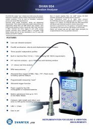
<strong>Complete</strong> <strong>RAS</strong> <strong>Systems</strong> <strong>for</strong> Stationary Applications<br />
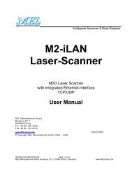
<strong>RAS</strong> systems combine proven rotec expertise <strong>and</strong> reliability with outst<strong>and</strong>ing flexibility <strong>and</strong> ease-of-use. The customer<br />
may begin with a basic system comprising only a few channels <strong>and</strong> st<strong>and</strong>ard software be<strong>for</strong>e later exp<strong>and</strong>ing<br />
to a system with many channels <strong>and</strong> a comprehensive range of data acquisition <strong>and</strong> analysis software.<br />
The modular architecture <strong>and</strong> versatile software make the equipment suitable <strong>for</strong> a wide range of testing <strong>and</strong> signal<br />
acquisition tasks.<br />
The <strong>RAS</strong> <strong>and</strong> USA systems are ideal <strong>for</strong> test-cell <strong>and</strong> laboratory measurements. Data acquisition <strong>and</strong> analysis are<br />
contained in a single unit. The <strong>RAS</strong> frame can accommodate up to 8 rotec data acquisition boards, the USA frame<br />
up to 12.<br />
<strong>RAS</strong><br />
◗ 3/4 19" frame, includes trigger <strong>and</strong> timing board.<br />
◗ Data acquisition <strong>and</strong> analysis system with 7 slots<br />
available <strong>for</strong> rotec data acquisition boards.<br />
rotec GmbH · Joseph-Dollinger-Bogen 18 · D-80807 Munich · Germany<br />
Tel: +49 (0) 89 323 651-0 · Fax: +49 (0) 89 323 651-56<br />
USA<br />
◗ 19" frame, includes trigger <strong>and</strong> timing board.<br />
◗ Data acquisition <strong>and</strong> analysis system with 11 slots<br />
available <strong>for</strong> rotec data acquisition boards.<br />
www.rotecmunich.de
DSE02-12.04 · <strong>Complete</strong> <strong>RAS</strong> <strong>Systems</strong> · © 2004 rotec GmbH, Munich · Subject to change without prior notice<br />
<strong>Measurement</strong> <strong>and</strong> <strong>Analysis</strong> <strong>Systems</strong><br />
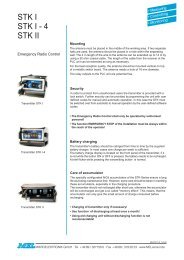
<strong>Complete</strong> <strong>RAS</strong> <strong>Systems</strong> <strong>for</strong> Stationary Applications<br />
CompactPCI Technology<br />
◗ Mobile Pentium M CPU, 1 Gbyte RAM, hard drive,<br />
floppy <strong>and</strong> MO drives<br />
◗ External interfaces: 2 x USB2.0, 2 x RS232, 1 x<br />
100Base Ethernet<br />
(RJ45), 1 x 1000Mbit Ethernet (RJ45), VGA<br />
◗ Internal IEEE-1394 interface<br />
◗ Hinged keyboard with touchpad / trackball<br />
◗ TFT 10.2" colour screen (800 x 600)<br />
◗ Microsoft Windows XP<br />
◗ Operating voltages: 110 / 220 V AC, 10 – 35 V DC,<br />
backup battery<br />
◗ Switchable cooling fan<br />
◗ <strong>RAS</strong> dimensions 20x36x43 (hxwxd),<br />
approx. wt. 18 kg<br />
◗ USA dimensions 20x47x43 (hxwxd),<br />
approx. wt. 20 kg<br />
rotec GmbH · Joseph-Dollinger-Bogen 18 · D-80807 Munich · Germany<br />
Tel: +49 (0) 89 323 651-0 · Fax: +49 (0) 89 323 651-56<br />
<strong>RAS</strong>19"<br />
◗ 19" rack mount system, includes trigger <strong>and</strong> timing<br />
board.<br />
◗ Data acquisition <strong>and</strong> analysis system with 3 slots<br />
available <strong>for</strong> rotec data acquisition boards.<br />
www.rotecmunich.de
DSE01-12.04 · Modular <strong>RAS</strong> <strong>Systems</strong> · © 2004 rotec GmbH, Munich · Subject to change without prior notice<br />
<strong>Measurement</strong> <strong>and</strong> <strong>Analysis</strong> <strong>Systems</strong><br />
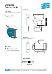
Modular <strong>RAS</strong> <strong>Systems</strong> <strong>for</strong> Mobile Applications<br />
<strong>RAS</strong> systems combine proven rotec expertise <strong>and</strong> reliability with outst<strong>and</strong>ing flexibility <strong>and</strong> ease-of-use. The customer<br />
may begin with a basic system comprising only a few channels <strong>and</strong> st<strong>and</strong>ard software be<strong>for</strong>e later exp<strong>and</strong>ing<br />
to a system with many channels <strong>and</strong> a comprehensive range of data acquisition <strong>and</strong> analysis software.<br />
The modular architecture <strong>and</strong> versatile software make the equipment suitable <strong>for</strong> a wide range of testing <strong>and</strong> signal<br />
acquisition tasks.<br />
<strong>RAS</strong>nbk<br />
<strong>Analysis</strong> <strong>and</strong> control unit. Notebook electrically <strong>and</strong><br />
mechanically modified. WindowsXP operating system.<br />
Fast, 60Gbyte hard-disk drive <strong>and</strong> CD R-W<br />
drive. Modem, USB, VGA, Ethernet, IEEE-1394 <strong>and</strong><br />
PCMCIA interfaces. Includes rotec carrying bag <strong>for</strong><br />
frontend <strong>and</strong> notebook.<br />
rotec GmbH · Joseph-Dollinger-Bogen 18 · D-80807 Munich · Germany<br />
Tel: +49 (0) 89 323 651-0 · Fax: +49 (0) 89 323 651-56<br />
Notebook <strong>and</strong> Frontend<br />
The combination of the control <strong>and</strong> analysis unit<br />
<strong>RAS</strong>nbk <strong>and</strong> <strong>RAS</strong> frontends is particularly suited to<br />
mobile applications. Three sizes of frontend frames<br />
are available – with 4, 8 or 12 slots – <strong>for</strong> rotec data<br />
acquisition boards. A single cable suffices (IEEE-<br />
1394, length 10m) <strong>for</strong> data exchange between the<br />
<strong>RAS</strong>nbk <strong>and</strong> the frontend acquisition unit. The flexible<br />
architecture allows <strong>for</strong> frontend configuration tailored<br />
to meet individual needs.<br />
www.rotecmunich.de
DSE01-12.04 · Modular <strong>RAS</strong>-<strong>Systems</strong> · © 2004 rotec GmbH, Munich · Subject to change without prior notice<br />
<strong>Measurement</strong> <strong>and</strong> <strong>Analysis</strong> <strong>Systems</strong><br />
Modular <strong>RAS</strong> <strong>Systems</strong> <strong>for</strong> Mobile Applications<br />
<strong>RAS</strong>FE08<br />
Data acquisition unit. 8-slot frontend. Includes trigger<br />
<strong>and</strong> timing board. 7 slots available <strong>for</strong> rotec data acquisition<br />
boards.<br />
<strong>RAS</strong>nb<br />
Data acquisition unit. 4-slot frontend. Includes trigger<br />
<strong>and</strong> timing board. 11 slots available <strong>for</strong> rotec data acquisition<br />
boards. Exp<strong>and</strong>able with <strong>RAS</strong>nb+.<br />
<strong>RAS</strong>FE12<br />
rotec GmbH · Joseph-Dollinger-Bogen 18 · D-80807 Munich · Germany<br />
Tel: +49 (0) 89 323 651-0 · Fax: +49 (0) 89 323 651-56<br />
Data acquisition unit. 12-slot frontend. Includes trigger<br />
<strong>and</strong> timing board. 11 slots available <strong>for</strong> rotec data<br />
acquisition boards.<br />
<strong>RAS</strong>nb+<br />
Data acquisition unit. Frontend expansion with 4 slots<br />
<strong>for</strong> rotec data acquisition boards.<br />
www.rotecmunich.de
DSE03-12.04 · <strong>RAS</strong>f1 · © 2004 rotec GmbH, Munich · Subject to change without prior notice<br />
<strong>Measurement</strong> <strong>and</strong> <strong>Analysis</strong> <strong>Systems</strong><br />
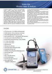
<strong>RAS</strong>f1 – <strong>for</strong> <strong>Measurement</strong>s on Racing Cars <strong>and</strong> Motorcycles<br />
<strong>RAS</strong>f1 is a st<strong>and</strong>alone system which can be used <strong>for</strong> multichannel measurement of both torsional vibration <strong>and</strong><br />
analogue signals. It complies with the full software <strong>and</strong> measurement board specifications of the st<strong>and</strong>ard <strong>RAS</strong><br />
systems. The main difference lies in the small size which, <strong>for</strong> example, allows <strong>for</strong> measurements on racing cars<br />
<strong>and</strong> motorcycles.<br />
<strong>RAS</strong>f1<br />
The <strong>RAS</strong>f1 Base Box contains the complete PC, the<br />
trigger board <strong>and</strong> three speed channels. A Single<br />
Board CPU designed <strong>for</strong> severe environments is<br />
used. It has no hard-disk drives. The operating system<br />
<strong>and</strong> <strong>RAS</strong> software are located on a Compact-<br />
Flash memory card.<br />
The acquired test data are stored on a second CompactFlash<br />
memory card. The software is configured<br />
so that the operating system loads automatically<br />
when powering up the system. The <strong>RAS</strong> software<br />
then starts <strong>and</strong> begins a measurement using the currently<br />
active measurement setup. Data acquisition<br />
can be started using the external trigger or by pushing<br />
a button on the remote "3-button operation" control<br />
unit.<br />
<strong>RAS</strong>f1 Base Box <strong>and</strong> <strong>RAS</strong>f1ana Extra Box<br />
rotec GmbH · Joseph-Dollinger-Bogen 18 · D-80807 Munich · Germany<br />
Tel: +49 (0) 89 323 651-0 · Fax: +49 (0) 89 323 651-56<br />
<strong>RAS</strong>f1rot <strong>and</strong> <strong>RAS</strong>f1ana<br />
The Base Box may be exp<strong>and</strong>ed with an Extra Box<br />
containing either four speed channels (<strong>RAS</strong>f1rot) or<br />
sixteen 50kHz analogue channels (<strong>RAS</strong>f1ana). Timing<br />
signals from the trigger board <strong>and</strong> the IEEE-1394<br />
connection are bussed via a flat ribbon cable. <strong>Measurement</strong><br />
signals <strong>and</strong> power input are fed via a<br />
Canon connector.<br />
Base Box<br />
◗ Dimensions: 185x150x50mm<br />
◗ Weight: 1400 g<br />
◗ Power required: 9 to 18V, 40W<br />
Extra Box<br />
◗ Dimensions: 185x150x35mm.<br />
◗ Weight: 950 g<br />
◗ Power required: 9 to 18V, 15W<br />
www.rotecmunich.de
DSE14-01.05 · Torsional Vibration Module DSM2 · © 2005 rotec GmbH, Munich · Subject to change without prior notice<br />
Sensors<br />
Torsional Vibration Module DSM2<br />
The DSM2 (DSM = Drehschwingungsmodul) is used in the investigation <strong>and</strong> monitoring of torsional vibration emitted<br />
by rotating machinery. The speed of rotation must be measured with a sensor which detects at equidistant<br />
angular intervals around the rotating shaft <strong>and</strong> whose output signal is a square wave TTL pulse train. Suitable<br />
sensors are, <strong>for</strong> example, incremental rotary encoders with integrated digitizing electronics or inductive / magnetoresistive<br />
proximity sensors <strong>and</strong> an accompanying pulse-<strong>for</strong>ming electronic unit. The DSM2 input frequency range<br />
is from 0.3Hz to 200kHz.<br />
The DSM2 determines the speed of rotation by<br />
measuring the periods of the TTL pulses. A fast digital<br />
signal processor converts these time values to<br />
speed or related units <strong>and</strong> outputs the data in real<br />
time as analogue voltages. The long wave signal<br />
components (= average speed) are separated from<br />
the short wave components (= speed fluctuation)<br />
<strong>and</strong> output on separate ±10V outputs, 'OUT1' <strong>and</strong><br />
'OUT2' respectively. The 'OUT1' analogue output provides<br />
in<strong>for</strong>mation on the mean angular velocity which<br />
is calculated as an arithmetic mean with unit rpm,<br />
rad/s, etc. A digital, low-pass filter with user-defined<br />
cut-off order is used. The speed fluctuation, angular<br />
acceleration or vibration angle may be output on<br />
'OUT2'. High accuracy is guaranteed <strong>for</strong> dynamic<br />
speed data since both of these outputs have 16 bit<br />
resolution.<br />
Output 'LIMIT' is especially useful <strong>for</strong> test-rig monitoring<br />
applications. The DSM may be added to the<br />
dynamometer control system to output an emergency<br />
stop signal when user-defined limiting values<br />
are exceeded. 'LIMIT' pre-trigger time data are saved<br />
internally to a 2Mb memory buffer allowing detailed<br />
post-process analysis using the rotec <strong>RAS</strong> software.<br />
rotec GmbH · Joseph-Dollinger-Bogen 18 · D-80807 Munich · Germany<br />
Tel: +49 (0) 89 323 651-0 · Fax: +49 (0) 89 323 651-56<br />
The module's settings are managed via USB interface<br />
<strong>and</strong> menu-driven software from an external PC<br />
or locally using the front panel buttons <strong>and</strong> display<br />
unit.<br />
Mechanically, the DSM2 is designed in Euro-<strong>for</strong>mat<br />
(3U) <strong>for</strong> 19" racks. Signal input <strong>and</strong> output is via the<br />
connectors integrated into the front panel or via the<br />
st<strong>and</strong>ard DIN connector on the module's rear. A suitable<br />
housing is provided with h<strong>and</strong>le <strong>and</strong> fold-away<br />
feet.<br />
www.rotecmunich.de
Setup<br />
The DSM may be configured either via USB interface<br />
from an external PC with a menu-driven software program<br />
or locally using the knob, buttons <strong>and</strong> display<br />
unit integrated into the front panel.<br />
Front panel mounted controls allow <strong>for</strong> input of parameters<br />
such as number of pulses per revolution,<br />
scaling of outputs <strong>and</strong> specifying the calculations<br />
which are to be made. These parameters as well as<br />
the results of calculations are shown on the integrated<br />
4-line ASCII display unit. Push buttons are used to<br />
select the physical quantities <strong>and</strong> their units while the<br />
www.rotecmunich.de<br />
knob is used to set their numerical values. Up to ten<br />
different setups may be stored in memory.<br />
The menu-driven software program (included) requires<br />
Windows 2000 or XP <strong>and</strong> a USB port. The<br />
software allows the user to configure parameters, install<br />
new firmware <strong>and</strong> store/retrieve time data in <strong>RAS</strong><br />
(rotmeas) <strong>for</strong>mat.<br />
The st<strong>and</strong>ard <strong>RAS</strong> software is required if further<br />
analysis of time data is required. Full <strong>RAS</strong> Evaluation<br />
functionality may then be applied to the rotmeas<br />
measurement files.
Calculations<br />
All calculations may be made in radians, degrees or<br />
revolutions. Results are continually shown on the<br />
internal numerical display unit <strong>and</strong> simultaneously<br />
output on 'OUT1' <strong>and</strong> 'OUT2' as scaled analogue<br />
voltages.<br />
Time Domain Calculations<br />
Angular velocity, vibration angle <strong>and</strong> angular acceleration<br />
may be calculated <strong>and</strong> output. Depending on<br />
the ordinate, the following calculations are available:<br />
◗ Vibration angle<br />
◗ Angular velocity<br />
◗ Speed fluctuation (high-pass, order filtered)<br />
◗ Angular acceleration<br />
The above calculations are per<strong>for</strong>med continuously,<br />
i.e. each pulse detected produces an updated result.<br />
Statistical Calculations<br />
Statistical <strong>and</strong> spectral calculations are per<strong>for</strong>med on<br />
moving blocks (the block size is a finite number of<br />
revolutions) <strong>and</strong> may be made <strong>for</strong> each of the amplitude<br />
quantities listed above:<br />
◗ Min. Values: The smallest value in the block is<br />
output on both the display unit <strong>and</strong> at 'OUT2'.<br />
This value is retained until it is either no longer<br />
present within the block or the calculation results<br />
in a smaller value.<br />
◗ Max. Values: Analogous to Min. Values.<br />
◗ Max.-Min. Values: Corresponds to peak-peak<br />
calculation.<br />
◗ Quadratic Mean: The rms value based on the<br />
block size may be calculated.<br />
Spectral Calculations<br />
Order domain calculations may also be carried out.<br />
Discrete orders as well as order summations may be<br />
output. Spectra of the vibration angle, angular velocity<br />
<strong>and</strong> angular acceleration may be calculated. The FFT<br />
method is used with a maximum of 1024 data points.<br />
Limits<br />
Upper / lower limiting values of discrete orders or<br />
order summations may be investigated <strong>for</strong> spectra<br />
<strong>and</strong>, <strong>for</strong> time data, the minimum, maximum or arithmetic<br />
mean. All investigations may be made as a<br />
function of the speed of rotation as listed in a table.<br />
Limiting values <strong>for</strong>:<br />
◗ Amplitudes: Vibration angle, angular velocity,<br />
angular acceleration.<br />
◗ Spectra: Discrete orders, order summations.<br />
◗ Time data: Minimum values, maximum values,<br />
arithmetic mean.<br />
◗ Exceeding of upper or lower limit.<br />
◗ All of this applies to either the complete speed<br />
range or a restricted speed range<br />
The DSM2 is also fitted with a 'Disable' input with<br />
which a calculation may be stopped. This function is<br />
used, <strong>for</strong> example, <strong>for</strong> temporary interruption of<br />
calculations during mechanical switching or coupling<br />
operations. Both the 'Disable' input <strong>and</strong> 'Limit' output<br />
signals are TTL level - High or Low.<br />
www.rotecmunich.de
DSE14-01.05 · Torsional Vibration Module DSM2 · © 2005 rotec GmbH, Munich · Subject to change without prior notice<br />
Specifications<br />
Inputs 1 TTL <strong>and</strong> 1 incremental encoder<br />
www.rotecmunich.de<br />
Sensors<br />
Torsional Vibration Module DSM2<br />
Input frequency range 0.3 Hz to 200 kHz<br />
Counter size 31 bits<br />
Counter clock 640MHz<br />
TTL input 'SENSOR' For rotec Digitizer,<br />
one bit reserved <strong>for</strong> direction<br />
of rotation<br />
8-pin Lemosa (small) connector<br />
Signal type TTL<br />
Minimum pulse width 100ns<br />
Input overload protection ±35V<br />
Input impedance 250Ω<br />
Sensor supply voltages +5V, +12V<br />
Incremental For st<strong>and</strong>ard encoders incl. 12-pin connector,<br />
encoder input supply voltages st<strong>and</strong>ard pinning<br />
'ENCODER' Edge detection x1<br />
Outputs<br />
Direction of rotation detection<br />
Processing of index pulse<br />
Signal type TTL differential<br />
St<strong>and</strong>ard outputs 2 identical outputs SMB connector<br />
'OUT1', 'OUT2' Voltage range ±10V, buffer<br />
Resolution 16 bits<br />
operational amplifier<br />
Settling time 10µs (max)<br />
Maximum output frequency 100kHz to 250kHz<br />
Calibration automatic at start of measurement<br />
Sync. output Single-channel SMB connector<br />
'REF' Output voltage TTL, buffered driver<br />
Clock output Single channel SMB connector<br />
'CLK' Output voltage TTL, buffered driver<br />
Pass / Fail output Single-channel SMB connector<br />
'LIM' Output voltage TTL, buffered driver<br />
rotec GmbH · Joseph-Dollinger-Bogen 18 · D-80807 Munich · Germany<br />
Tel: +49 (0) 89 323 651-0 · Fax: +49 (0) 89 323 651-56
DSE04-12.04 · Data Acquisition Boards · © 2004 rotec GmbH, Munich · Subject to change without prior notice<br />
<strong>RAS</strong> Data Acquisition Boards<br />
Trigger, Speed, Analogue<br />
Trigger <strong>and</strong> Timing Board (E-TR)<br />
This board provides the central time base <strong>for</strong> all<br />
measurement channels <strong>and</strong> also contains an input<br />
<strong>for</strong> external start signals (8-pin Lemosa, connector<br />
compatible with speed board).<br />
◗ Monitoring of operating voltages<br />
◗ LED <strong>for</strong> input<br />
◗ Triggering by means of 32-bit DSP,<br />
firmware in RAM<br />
Rotational Speed Board (E-DR)<br />
These boards measure the periodic times of digital<br />
speed signals. One board is required per speed signal.<br />
Many boards are synchronised by the trigger<br />
board.<br />
◗ Single-channel, 8-pin Lemosa connector<br />
◗ 10 GHz (100 psec) counter/timer<br />
◗ 40-bit counter size<br />
◗ TTL-level input signals, voltage overload protection<br />
±40 V<br />
◗ Input frequency range from 0.01 Hz to 1 MHz<br />
◗ Input <strong>for</strong> rotational direction<br />
◗ 2 additional digital inputs<br />
◗ Provides sensor supply voltages<br />
◗ Start/Stop triggering on speed threshold<br />
or gradient<br />
◗ LEDs <strong>for</strong> inputs<br />
◗ Signal pre-processing by means of 32-bit DSP.<br />
Firmware in RAM<br />
8-channel Analogue Board (E-AN)<br />
These boards are designed <strong>for</strong> analogue sampling<br />
of the input signal. The trigger board ensures synchronisation<br />
of analogue <strong>and</strong> speed measurements.<br />
◗ Eight channels, SMB connectors<br />
◗ 50 kHz sampling rate per channel<br />
◗ 16-bit resolution<br />
◗ Input signals ±10 V, differential or current source<br />
◗ Voltage overload protection ±500 V<br />
◗ Input impedance differential 0.8 MOhm / 150 pF,<br />
Common mode 0.25 MOhm / 36pF<br />
rotec GmbH · Joseph-Dollinger-Bogen 18 · D-80807 Munich · Germany<br />
Tel: +49 (0) 89 323 651-0 · Fax: +49 (0) 89 323 651-56<br />
◗ 10 kHz hardware filter, switchable<br />
◗ Separate setting of sampling rate <strong>for</strong> each channel<br />
from 3Hz to 50kHz<br />
◗ Programmable amplification 1, 10, 100, 1000<br />
◗ AC/DC coupling<br />
◗ Start/Stop triggering on level or gradient<br />
◗ LED <strong>for</strong> input voltage overload<br />
◗ Signal pre-processing by means of 32-bit DSP.<br />
Firmware in RAM<br />
2-channel Analogue Board (E-A2)<br />
These boards are designed <strong>for</strong> analogue sampling of<br />
the input signal. The trigger board ensures synchronisation<br />
of analogue <strong>and</strong> speed measurements.<br />
◗ Two channels, SMB connectors<br />
◗ 400 kHz sampling rate per channel<br />
◗ 16-bit resolution<br />
◗ Input signals ±10 V, differential or current source<br />
◗ Voltage overload protection ±500 V<br />
◗ Input impedance differential 107 MOhm / 150 pF,<br />
Common mode 0.25 MOhm / 36pF<br />
◗ 10 kHz hardware filter, switchable<br />
◗ Separate setting of sampling rate <strong>for</strong> each channel<br />
from 3Hz to 400kHz<br />
◗ Programmable amplification 1, 10, 100, 1000<br />
◗ AC/DC coupling<br />
◗ Start/Stop triggering on level gradient<br />
◗ LED <strong>for</strong> input voltage overload<br />
◗ Signal pre-processing by means of 32-bit DSP.<br />
Firmware in RAM<br />
www.rotecmunich.de
DSE07-12.04 · St<strong>and</strong>ard Speed Sensors · © 2004 rotec GmbH, Munich · Subject to change without prior notice<br />
Sensors<br />
St<strong>and</strong>ard Rotational Speed Sensors<br />
The rotec sensors described here are designed <strong>for</strong> non-contact measurement of the rotational speed of a toothed<br />
wheel. Each sensor consists of two magnetoresistive elements <strong>and</strong> a permanent magnet enclosed in a stainless<br />
steel cylindrical housing with M10x1 outer thread. The sensors themselves are entirely passive. For operation they<br />
require an accompanying electronic unit which converts their analogue output to a TTL signal. The sensors exhibit<br />
minimal temperature dependence <strong>and</strong> their operation is not impaired by dirt or oil films. The output signal<br />
amplitude is independent of the rotational speed. A variety of lengths <strong>and</strong> designs is available.<br />
The sensors' stainless steel cylindrical housing has an M10x1 outer thread. The target wheel should have a gear<br />
module in the range 0.6 to 2.4mm, a pitch between 1.9 <strong>and</strong> 7.7mm <strong>and</strong> a thickness of at least 5mm. A sensing<br />
gap from sensor to wheel of up to 5mm is allowed <strong>for</strong>. The electronic unit operates <strong>for</strong> the tooth frequency range<br />
0.1Hz to 20 kHz, i.e. a tooth must be detected at least once every ten seconds. Differential magnetoresistive sensors<br />
need to be carefully positioned <strong>for</strong> both optimal adjustment of orientation w.r.t. the target wheel <strong>and</strong> setting<br />
of sensing distance.<br />
<strong>Measurement</strong> Principle Main Features:<br />
◗ M10x1 outer thread<br />
◗ Target wheel: ferromagnetic material<br />
Gear module: 0.6mm to 2.4mm<br />
Pitch: 1.9mm to 7.7mm<br />
◗ Sensing gap up to 5mm<br />
◗ Tooth frequency range: 0.1Hz to 20kHz<br />
◗ Sensor electronic unit: input 5mV to approx 80V,<br />
output TTL level (0/5V)<br />
rotec GmbH · Joseph-Dollinger-Bogen 18 · D-80807 Munich · Germany<br />
Tel: +49 (0) 89 323 651-0 · Fax: +49 (0) 89 323 651-56<br />
www.rotecmunich.de
DSE07-12.04 · St<strong>and</strong>ard Speed Sensors · © 2004 rotec GmbH, Munich · Subject to change without prior notice<br />
Sensors<br />
St<strong>and</strong>ard Rotational Speed Sensors<br />
Sensor Type A<br />
Sensor Type C<br />
St<strong>and</strong>ard Sensor Electronic Unit<br />
Sensor Type B<br />
rotec GmbH · Joseph-Dollinger-Bogen 18 · D-80807 Munich · Germany<br />
Tel: +49 (0) 89 323 651-0 · Fax: +49 (0) 89 323 651-56<br />
Cable <strong>for</strong> Sensor Type B <strong>and</strong> C<br />
Inline Sensor Electronic Unit<br />
www.rotecmunich.de
DSE08-12.04 · Fourfold Sensors · © 2004 rotec GmbH, Munich · Subject to change without prior notice<br />
Sensors<br />
Fourfold Rotational Speed Sensors<br />
The rotec 'fourfold sensor' is used in order to increase the angular resolution of rotational-speed measurements.<br />
The sensors are used when the target wheels have a relatively small number of teeth, e.g. chain sprockets or<br />
gears within a gearbox. Each scanned tooth provides four data points. The sensor comprises 4 magnetoresistive<br />
elements with a permanent magnet enclosed in a stainless steel casing with M10x1 outer thread. The sensors require<br />
an accompanying electronic unit which converts their analogue output voltage to square wave TTL level. The<br />
sensors exhibit minimal temperature dependence <strong>and</strong> their operation is not impaired by dirt or oil films.<br />
Main Features:<br />
◗ Outer thread M10x1<br />
◗ Target wheel: ferromagnetic material<br />
Gear module: 1mm to 2.5mm<br />
Pitch: 2mm to 6mm, ideally 2.5mm<br />
◗ Tooth frequency range: 1Hz to approx. 45kHz<br />
◗ Sensing gap up to approx. 1.5mm<br />
The sensor's stainless steel cylindrical housing has<br />
an M10x1 outer thread. The target wheel should have<br />
a gear module in the range 1 to 2.5, a pitch between<br />
2 <strong>and</strong> 6mm <strong>and</strong> a thickness of at least 5mm. A sensing<br />
gap from sensor to wheel of up to approx. 1.5mm<br />
is allowed <strong>for</strong>. The electronic unit operates <strong>for</strong> the<br />
tooth frequency range 1Hz to approx. 45 kHz. The<br />
magnetoresistor arrangement dem<strong>and</strong>s that the sen-<br />
rotec GmbH · Joseph-Dollinger-Bogen 18 · D-80807 Munich · Germany<br />
Tel: +49 (0) 89 323 651-0 · Fax: +49 (0) 89 323 651-56<br />
sors need to be carefully positioned <strong>for</strong> both optimal<br />
adjustment of orientation w.r.t. the target wheel <strong>and</strong><br />
setting of sensing distance. An 'eightfold sensor'<br />
which provides eight pulses per tooth is also available.<br />
<strong>Measurement</strong> Principle<br />
www.rotecmunich.de
DSE09-12.04 · Speed Sensor with Rotational Direction · © 2004 rotec GmbH, Munich · Subject to change without prior notice<br />
Sensors<br />
Speed Sensor with Direction of Rotation<br />
The rotec 'fourfold sensor' may be used both to measure rotational speed <strong>and</strong> detect the direction of rotation. The<br />
sensor comprises four magnetoresistive elements <strong>and</strong> a permanent magnet encapsulated in a stainless steel<br />
housing with M10x1 outer thread. The magnetoresistors are arranged in pairs as two differential sensors [1 & 2 –<br />
see drawing below left]. The special electronic unit generates two phase-shifted speed-dependent signals. The<br />
first square-wave TTL pulse train constitutes the actual speed signal. The second pulse train is required <strong>for</strong> determining<br />
the direction of rotation. Both the first pulse train (speed signal) <strong>and</strong> a single bit (direction of rotation)<br />
are output to the <strong>RAS</strong> analyser.<br />
The sensor's stainless steel cylindrical housing has an M10x1 outer thread. The ferromagnetic target wheel should<br />
have a gear module in the range 0.6mm to approx. 2.4mm, a pitch between 2mm <strong>and</strong> 7mm <strong>and</strong> a thickness of at<br />
least 5mm. A sensing gap from sensor to wheel of up to approx. 2mm is admissable.<br />
The electronic unit operates <strong>for</strong> the tooth frequency range 0.1Hz to approx. 20 kHz. The magnetoresistor<br />
arrangement dem<strong>and</strong>s that the sensors need to be carefully positioned <strong>for</strong> both optimal adjustment of orientation<br />
w.r.t the target wheel <strong>and</strong> setting of sensing distance.<br />
Main Features:<br />
◗ Outer thread M10x1<br />
◗ Target wheel: ferromagnetic material<br />
Gear module: 0.6mm to 2.4mm<br />
Pitch: 2mm to 7mm<br />
◗ Tooth frequency range: 0.1Hz to approx. 20kHz<br />
◗ Sensing gap up to approx. 2mm<br />
rotec GmbH · Joseph-Dollinger-Bogen 18 · D-80807 Munich · Germany<br />
Tel: +49 (0) 89 323 651-0 · Fax: +49 (0) 89 323 651-56<br />
<strong>Measurement</strong> Principle<br />
www.rotecmunich.de
DSE10-12.04 · Laser Tachometer · © 2004 rotec GmbH, Munich · Subject to change without prior notice<br />
Sensors<br />
Laser Tachometer<br />
The Laser Tachometer is a non-contact instrument which allows the user to measure the speed of rotation of a<br />
rotating component whose surface is fitted with an encoder consisting of alternate white <strong>and</strong> black sectors. Light<br />
which is reflected from the white sectors is received <strong>and</strong> digitised. Analogous to the scanning of a toothed wheel<br />
with a magnetic sensor, the electronic unit outputs a TTL pulse train whose frequency is proportional to the speed<br />
of rotation of the encoder. The use of visible light means that the user can easily aim the red-coloured beam spot<br />
onto the encoder target.<br />
Operating principle<br />
The complete tachometer system consists of an<br />
electronic unit <strong>and</strong> passive sensor head with integrated<br />
duplex fibre optic cable. The electronic unit<br />
contains a power-regulated emitter diode with wavelength<br />
670nm. The sensor head / duplex cable assembly<br />
is attached to the electronic unit with optically<br />
coupled connectors. The sensor head serves to<br />
both direct the light beam to the target, detect the reflected<br />
light <strong>and</strong> feed it back to the electronic unit's<br />
receiving diode. A control circuit compensates <strong>for</strong><br />
varying sensing distances <strong>and</strong> degrees of surface<br />
reflection.<br />
As with all rotec sensors, power requirements are<br />
provided by the <strong>RAS</strong> system via 8-pin cable. Functionality<br />
is checked by an LED 'Lock' which illuminates<br />
when the encoder properly switches from reflecting<br />
to non-reflecting.<br />
rotec GmbH · Joseph-Dollinger-Bogen 18 · D-80807 Munich · Germany<br />
Tel: +49 (0) 89 323 651-0 · Fax: +49 (0) 89 323 651-56<br />
As with all <strong>for</strong>ms of laser radiation the user should<br />
avoid direct eye exposure.<br />
Main features:<br />
◗ Class II laser device<br />
◗ Laser wavelength 670 ±10nm<br />
◗ Laser power 1mm<br />
◗ Distance to encoder surface using white diffuse<br />
paper: 20mm to 70mm<br />
◗ Power consumption on 12V line: 100mA<br />
◗ Operating temperature: 0 to 50°C (electronics),<br />
-40 to 120°C (optics)<br />
◗ Optical head outer thread: Imperial 1/2"<br />
<strong>Measurement</strong> setup<br />
www.rotecmunich.de
DSE11-12.04 · Rotary Encoder Adapter · © 2004 rotec GmbH, Munich · Subject to change without prior notice<br />
Sensors<br />
Rotary Encoder Adapter Unit<br />
Incremental rotary encoders provide in<strong>for</strong>mation on the angular position of rotating shafts. The encoders generate<br />
two incremental signals, phase shifted to each other by 90° el., <strong>and</strong> a reference mark signal (once per revolution).<br />
These signals provide in<strong>for</strong>mation which can be used in the determination of both the shaft's rotational<br />
speed <strong>and</strong> its direction of rotation.<br />
The DGADP signal conditioning unit described here is used <strong>for</strong> conditioning rotary encoder signals. Pulses can<br />
be measured in both the <strong>for</strong>ward <strong>and</strong> reverse directions. The unit can be configured to measure various combinations<br />
of the distances between the edges of both pulse trains. An integrated divider circuit allows <strong>for</strong> reduction<br />
of the number of sampled pulses with dividing factors ranging from 1 to 215 . It is also possible to suppress a pulse<br />
from the first pulse train each time the index pulse (once per revolution) is detected. Setup is accomplished with<br />
DIP switches. Built-in green <strong>and</strong> red LEDs indicate direction of rotation <strong>and</strong> detection of the index pulse respectively.<br />
<strong>Measurement</strong> Principle<br />
The encoders used should provide two 90° el. phaseshifted<br />
TTL square-wave pulse trains <strong>and</strong> an index<br />
pulse signal. The provision of two phase-shifted signals<br />
makes recognition of the direction of rotation<br />
possible. The encoders should also provide the inverted<br />
signals of the pulse trains since this aids in<br />
noise suppression.<br />
The electronics package is contained in an aluminium<br />
case. The power requirements are provided by<br />
the <strong>RAS</strong> analyser via an integrated 8-pin Lemosa<br />
socket. This connector also carries the output TTL<br />
signal. The encoder is connected to the 12-pin flange<br />
socket. For configuring the unit the top may be detached<br />
to allow access to the DIP switches.<br />
Setup<br />
Dividing factor: Dividing factors in the range 1 to 215 may be set:<br />
Interpolation / edge detection: Three different modes<br />
<strong>for</strong> detection of the edges of the TTL pulse trains<br />
may be set. (i) Only the positive edge of pulse train<br />
no. 1 is measured. (ii) Both the positive <strong>and</strong> negative<br />
edges of pulse train no. 1 are measured (interpola-<br />
rotec GmbH · Joseph-Dollinger-Bogen 18 · D-80807 Munich · Germany<br />
Tel: +49 (0) 89 323 651-0 · Fax: +49 (0) 89 323 651-56<br />
tion x2). (iii) The rising <strong>and</strong> falling edges of both<br />
pulse trains are measured (interpolation x4).<br />
Pulse suppression: A pulse is suppressed each time<br />
the index pulse is detected.<br />
Main features:<br />
◗ Input signal: Square-wave TTL<br />
(both pulse trains <strong>and</strong> index pulse)<br />
◗ Output signal: Square-wave TTL<br />
◗ Max. encoder input frequency:<br />
14 MHz <strong>for</strong> mode (i) - no interpolation<br />
8 MHz <strong>for</strong> mode (ii) - interpolation x2<br />
4.5 MHz <strong>for</strong> mode (iii) - interpolation x4<br />
◗ Output signal pulse width: 24ns<br />
◗ Operating temperature: 0 … +50°C<br />
www.rotecmunich.de
DSE12-12.04 · TTL Signal Adapter Unit · © 2004 rotec GmbH, Munich · Subject to change without prior notice<br />
Sensors<br />
TTL Signal Adapter Unit<br />
When the angular velocity (speed of rotation) of a rotating shaft is to be measured, sensors which detect at constant<br />
angular intervals around the shaft's circumference are widely used. The signal resulting from this type of<br />
measurement is a square-wave TTL pulse train whose frequency is proportional to the shaft's angular velocity. The<br />
periodic times (T) of the pulses (time interval from positive edge to positive edge) may then be measured with a<br />
high-speed counter/timer data acquisition board. The instantaneous angular velocity is then calculated by dividing<br />
the angle between the measuring points on the shaft circumference by the time intervals (T) from pulse to<br />
pulse.<br />
The TTLAD unit from rotec is used <strong>for</strong> detection of<br />
positive (rising) <strong>and</strong> or negative (falling) TTL-signal<br />
edges. Each time a positive <strong>and</strong>/or negative edge is<br />
detected the unit outputs a 10µs wide pulse<br />
Main Features:<br />
◗ Input signal: TTL level pulse train<br />
◗ Output signal: TTL level, 10µs pulse width<br />
◗ Maximum input frequency: 49kHz<br />
◗ Delay time: maximum 40ns<br />
◗ Supply voltage: 5V<br />
Switch Settings<br />
There are three 'edge' switch settings: – 'pos', 'neg'<br />
<strong>and</strong> 'both'. The 'pos' (=positive) setting produces output<br />
pulses when positive edges are detected on the<br />
rotec GmbH · Joseph-Dollinger-Bogen 18 · D-80807 Munich · Germany<br />
Tel: +49 (0) 89 323 651-0 · Fax: +49 (0) 89 323 651-56<br />
input signal. The 'neg' (=negative) setting produces<br />
output pulses when negative edges are detected on<br />
the input signal. The 'both' setting produces output<br />
pulses when positive <strong>and</strong> negative edges are detected<br />
on the input signal.<br />
The TTL Adapter operates up to an input frequency<br />
of 49kHz (TTL input signals). The delay time between<br />
the input <strong>and</strong> output signal has a maximum<br />
value of 40ns. The supply voltage is 5V <strong>and</strong> the input<br />
is protected to ±80V.<br />
Input <strong>and</strong> Output Signals<br />
www.rotecmunich.de
DSE13-12.04 · 3-Button Unit · © 2004 rotec GmbH, Munich · Subject to change without prior notice<br />
Sensors<br />
3-Button-Operation Unit<br />
The 3-Button Unit may be connected with a cable to the serial port of an IEEE-1394 ('Firewire') <strong>RAS</strong> system. The<br />
<strong>RAS</strong> system may then, <strong>for</strong> example, be installed in the boot of the car undergoing test <strong>and</strong> the 3-Button Unit allows<br />
the driver to run the tests remotely. This applies only to the actual starting <strong>and</strong> stopping of measurements.<br />
All <strong>RAS</strong>-Software setups must be made be<strong>for</strong>eh<strong>and</strong> via keyboard. The small 3-Button Unit is connected by an integrated<br />
cable to a RS232 port of the <strong>RAS</strong> system, <strong>RAS</strong>nbk or <strong>RAS</strong>f1 system. The computer is configured so that<br />
login automatically follows system operating voltage switch-on. Login then follows automatically, the <strong>RAS</strong> software<br />
starts <strong>and</strong> the appropriate measurement setup is activated. Automatic saving of the measurement data is also<br />
provided <strong>for</strong>.<br />
Setup<br />
This mode of operation is activated in the main <strong>RAS</strong><br />
menu bar 'Extras / 3-Button Operation' together with<br />
selection of a serial port. Settings considered important<br />
<strong>for</strong> 3-Button Operation are highlighted in yellow.<br />
When this mode of operation is selected the 'Measure'<br />
function automatically starts when the <strong>RAS</strong> software<br />
is started. 3-Button Operation is stopped by<br />
pressing 'Close' in the measurement dialogue box<br />
with mouse or keyboard followed by de-selecting the<br />
'Activate 3-Button Operation <strong>for</strong> <strong>Measurement</strong>' check<br />
box. The rasmain.exe program may be added to the<br />
Windows Startup Menu ensuring automatic execution.<br />
Operation<br />
LEDs are integrated into the 3 buttons. A button's<br />
LED being ON indicates that the button may be<br />
pressed. Pressing a button otherwise has no effect<br />
on the program. Once the system has booted <strong>and</strong><br />
rotec GmbH · Joseph-Dollinger-Bogen 18 · D-80807 Munich · Germany<br />
Tel: +49 (0) 89 323 651-0 · Fax: +49 (0) 89 323 651-56<br />
the <strong>RAS</strong> measurement program is primed, the green<br />
Start Button's LED is illuminated. In cases of error an<br />
appropriate message is shown on the screen<br />
(<strong>RAS</strong>sys <strong>and</strong> <strong>RAS</strong>nbk). A monitor may be connected<br />
to the VGA port of the <strong>RAS</strong>f1 system to aid in finding<br />
the source of error.<br />
Buttons:<br />
Green Start - Start the measurement<br />
Orange Stop - Stop the measurement<br />
Red Shutdown - Close the program<br />
<strong>and</strong> shutdown the operating system.<br />
A double-click of the button within two<br />
seconds is required to protect against<br />
incorrect operation.<br />
LEDs:<br />
Orange Waiting - Awaiting trigger condition<br />
Green Measuring - <strong>Measurement</strong> is running<br />
Orange Saving - Data are being saved<br />
Red Error<br />
www.rotecmunich.de
DSE05-12.04 · <strong>RAS</strong> Software Overview · © 2004 rotec GmbH, Munich · Subject to change without prior notice<br />
<strong>RAS</strong> Software<br />
Overview<br />
<strong>RAS</strong> systems combine proven rotec expertise <strong>and</strong> reliability with outst<strong>and</strong>ing flexibility <strong>and</strong> ease-of-use. The customer<br />
may begin with a basic system comprising only a few channels <strong>and</strong> st<strong>and</strong>ard software <strong>and</strong> later exp<strong>and</strong> to<br />
a system with many channels <strong>and</strong> a comprehensive range of data acquisition <strong>and</strong> analysis software. The modular<br />
architecture <strong>and</strong> versatile software make the equipment suitable <strong>for</strong> a wide range of testing <strong>and</strong> signal acquisition<br />
tasks.<br />
The <strong>RAS</strong> software provides the user with an easy-to-use, flexible <strong>and</strong> powerful tool <strong>for</strong> data acquisition <strong>and</strong> analysis.<br />
Signals may be analysed as a function of time, angle or rotational speed. FFT methods are used when converting<br />
from the time to the frequency <strong>and</strong> order domains. The common time base of all channels ensures reliable<br />
cross-channel evaluation of signals (e.g. transmission error or torque between two speed channels) <strong>and</strong> allows<br />
<strong>for</strong> correlation of analogue signals with speed data.<br />
The powerful <strong>RAS</strong> hardware allows <strong>for</strong> comprehensive time <strong>and</strong> spectral analyses with online display during the<br />
measurement. Immediately following the measurement, the time history data are stored on hard-disk.<br />
Setup of hardware <strong>and</strong> software <strong>for</strong> a test sequence<br />
is straight<strong>for</strong>ward by means of easy-to-follow<br />
menus.<br />
Data analysis may be per<strong>for</strong>med on the <strong>RAS</strong> system<br />
itself or on a desktop PC. Created graphic images<br />
can be exported to other applications via the Clipboard<br />
or Windows Metafiles.<br />
rotec GmbH · Joseph-Dollinger-Bogen 18 · D-80807 Munich · Germany<br />
Tel: +49 (0) 89 323 651-0 · Fax: +49 (0) 89 323 651-56<br />
Animation software helps interpretation of measurement<br />
results by means of animated wireframe<br />
models.<br />
Simulation software generates mathematical models<br />
of the system undergoing test with frequency domain<br />
analysis.<br />
www.rotecmunich.de
DSE05-12.04 · <strong>RAS</strong> Software Overview · © 2004 rotec GmbH, Munich · Subject to change without prior notice<br />
<strong>RAS</strong> Software<br />
Overview<br />
Data Evaluation<br />
The <strong>RAS</strong> evaluation software is structured as follows:<br />
Firstly, a Synthesis may be applied to the raw data<br />
(e.g. inserting a missing tooth into the time history<br />
data). Then an <strong>Analysis</strong> may be per<strong>for</strong>med on this intermediate<br />
result (e.g. calculation of the vibration<br />
angle versus time). Extras may then be applied to this<br />
new intermediate result (e.g. smoothing a curve). The<br />
end result is then incorporated into a Diagram whereby<br />
axes may be <strong>for</strong>matted. This is followed by generation<br />
of Pages, i.e. completed sheets <strong>for</strong> printer output.<br />
Evaluation sequences may be saved as macros<br />
<strong>for</strong> application at any time.<br />
Syntheses<br />
A Synthesis allows <strong>for</strong> pre-processing of raw data.<br />
The output data are then input to an <strong>Analysis</strong>. The<br />
following Syntheses are available <strong>for</strong> both speed<br />
<strong>and</strong> analogue data:<br />
◗ Removal of speed channel markings<br />
◗ Pitch error correction of toothed wheels<br />
◗ Special speed sensors<br />
◗ Filtering<br />
◗ Level rating<br />
◗ Vector operations<br />
◗ Strain guage rosettes<br />
◗ Analogue sensor characteristic curves<br />
Analyses<br />
An <strong>Analysis</strong> is a calculation per<strong>for</strong>med on speed,<br />
analogue or CAN data. The following ordinates are<br />
available <strong>for</strong> all <strong>Analysis</strong> types:<br />
<strong>for</strong> speed channels<br />
◗ Rotational speed in [rpm], speed fluctuation in<br />
[rpm]<br />
◗ Angular velocity in [deg/s], [rad/s]<br />
◗ Vibration angle in [deg], [rad]<br />
◗ Angular acceleration in [deg/s2 ], [rad/s2 ]<br />
<strong>for</strong> analogue channels<br />
◗ Analogue value<br />
◗ 1st <strong>and</strong> 2nd derivative, 1st <strong>and</strong> 2nd integral<br />
rotec GmbH · Joseph-Dollinger-Bogen 18 · D-80807 Munich · Germany<br />
Tel: +49 (0) 89 323 651-0 · Fax: +49 (0) 89 323 651-56<br />
<strong>for</strong> 2-channel speed evaluations<br />
◗ Angle of twist / torque, transmission error in<br />
[µm], [µrad], [deg], [arc sec]<br />
◗ Speed difference in [rpm]<br />
◗ Slip [1] or in [%]<br />
Time history<br />
Single <strong>and</strong> difference channel calculations versus<br />
time, angle or revolutions.<br />
Angle<br />
Single <strong>and</strong> difference channel calculations versus<br />
angle. Waterfall or 2-dim cuts. Sub-division of measurement<br />
into cycles of finite size (user-defined).<br />
Pitch error correction<br />
Determination of tooth-to-tooth spacing error <strong>for</strong> subsequent<br />
correction.<br />
Valvetrain<br />
Special analyses <strong>for</strong> valvetrain measurements – lift,<br />
closing velocity, bounce, etc.<br />
Gear Testing<br />
Single flank testing of gearsets incl. differentials <strong>and</strong><br />
multi-staged gears.<br />
Spectral domain<br />
Order <strong>and</strong> frequency analysis. Amplitudes, phases,<br />
vector plots <strong>and</strong> inverse trans<strong>for</strong>mations.<br />
Peak, peak to peak, rms, linear, logarithmic.<br />
2-dim <strong>and</strong> 3-dim plots, contour <strong>and</strong> Campbell plots<br />
versus time or speed. Several calculation methods <strong>for</strong><br />
summation (overall level).<br />
Octave filter<br />
2-dim or Waterfall plot of results of octave-filtered<br />
data.<br />
Extras<br />
These tools are designed <strong>for</strong> post-processing of the<br />
results of an <strong>Analysis</strong>. Examples are smoothing of<br />
curves, statistical calculations <strong>and</strong> ASCII conversion.<br />
◗ Scaling<br />
◗ Statistics <strong>for</strong> 2-dim <strong>and</strong> Waterfall plots<br />
◗ Spectrum with up to 16k lines<br />
◗ Filter designer<br />
◗ Smoothing<br />
◗ Correlation<br />
◗ General <strong>for</strong>mula, pocket calculator function <strong>for</strong><br />
curves<br />
◗ Limits<br />
◗ Data conversion<br />
www.rotecmunich.de
DS06-12.04 · Einflankenwälzprüfung · © 2004 rotec GmbH, München<br />
Software<br />
Einflankenwälzprüfung<br />
Die Qualität eines Getriebes wird immer stärker durch seine Geräuschemissionen bestimmt. Unter-suchungsmethoden<br />
wie Geräusch- und Einflankenwälzprüfung erlangen somit eine wachsende Bedeutung. Die konventionelle<br />
Einflankenwälzprüfung, die definitionsgemäß bei niedrigen Drehzahlen (ca. 20 Upm) und nahezu lastfrei durchgeführt<br />
wird, eignet sich sehr gut zur Beurteilung der Fertigungsqualität von Verzahnungen. Eine Beurteilung des<br />
im realen Betrieb zu erwartenden Lauf- und Geräuschverhaltens er<strong>for</strong>dert jedoch eine Wälzprüfung unter Last<br />
und Betriebsdrehzahl.<br />
Einflankenwälzprüfung<br />
Idealerweise sollte ein Zahnradpaar eine Drehbewegung<br />
gleichförmig übertragen. Die Wälzabweichung<br />
ist die Differenz zwischen der gemessenen Position<br />
eines Zahnrades und der Position, die dieses einnehmen<br />
müßte, falls die Räder des Zahnradpaares<br />
perfekt zuein<strong>and</strong>er passen würden.<br />
Wälzabweichungsmessung<br />
Meist besteht der Meßaufbau aus der Adaption<br />
zweier hochauflösender Winkelschrittgeber an den<br />
Achsen der zu untersuchenden Zahnräder. Das rotec<br />
System mißt auf An- und Abtriebsseite die Durchgangszeiten<br />
der Strichsegmente. Man erhält so die<br />
Winkelpositionen von Rad und Ritzel, woraus die<br />
Wälzabweichung berechnet wird. Die Auflösung bei<br />
dieser Meßmethode ist aufgrund der hohen Taktfrequenz<br />
der Meßkanäle sehr hoch. Desweiteren ist<br />
durch die Auswertung jedes Striches eine exakte<br />
Nachbildung der einzelne Zahneingriffe möglich.<br />
Die Kurve des Gesamtfehlers (Einflanken-Wälzabweichung)<br />
resultiert aus der Berechnung der Winkelabweichung<br />
zwischen beiden Winkelschrittgebern. Der<br />
angezeigte Verlauf zeigt dann die Exzentrizät der<br />
beiden Wellen sowie den Zahneingriff. Man erkennt<br />
ein kurzperiodisches Muster, welches sich einmal pro<br />
Zahn wiederholt, und eine langwellige Komponente,<br />
die sich einmal pro Umdrehung wiederholt. Der<br />
kurzwellige Anteil (einmal pro Zahn oder öfter) resultiert<br />
aus der Verzahnungsgeometrie (Balligkeit, usw.)<br />
sowie aus Unregelmäßigkeiten der Zahnoberflächen.<br />
Der langwellige Anteil entsteht durch Rundlauffehler<br />
beider Räder. Zusätzlich können Anteile<br />
vorh<strong>and</strong>en sein, die z.B. durch Befestigungsbohrungen<br />
verursacht werden und keinen Bezug zum Zahneingriff<br />
haben.<br />
rotec GmbH · Joseph-Dollinger-Bogen 18 · D-80807 München<br />
Tel: +49 (0) 89 323 651-0 · Fax: +49 (0) 89 323 651-56<br />
Um ein komplettes Bild des Zahneingriffsverhaltens<br />
zu erhalten, sollte mindestens eine komplette Überrollung<br />
vermessen werden. Das rotec-Programm<br />
kann dann durch geeignete Mittelungsverfahren<br />
zwischen Tellerrad und Ritzel separieren. Der langwellige<br />
Anteil entsteht durch Tiefpaßfilterung des Signals<br />
mit einer Eckordnung bei 1/3 des Zahneingriffs.<br />
Wird diese Kurve vom Gesamtsignal subtrahiert,<br />
bleibt der kurzwellige Anteil.<br />
Andere Meßgrößen<br />
Neben der Wälzabweichung ermöglicht das rotec-<br />
Meßsystem die Aufnahme und Berechnung von<br />
weiteren Größen wie die Drehbeschleunigungen von<br />
Rad und Ritzel, der Körperschall an den Lagerstellen,<br />
sowie der abgestrahlte Luftschall. Das Meßsystem<br />
gewährleistet die zeitgleiche Erfassung aller<br />
Meßgrößen. Da eine Ordnungsanalyse aller Signale<br />
möglich ist, können beispielsweise Zusammenhänge<br />
zwischen der Wälzabweichung und der Geräuschentwicklung<br />
einer Verzahnung aufgezeigt werden.<br />
DIN Werte<br />
F ' i Gesamtfehler (Einflanken-Wälzabweichung )<br />
f' l langwelliger Anteil<br />
f' k kurzwelliger Anteil<br />
f' max Maximalwert des Zahn-zu-Zahn-Fehlers<br />
(Einflanken-Wälzsprung)<br />
f' mit mittlerer Zahn-zu-Zahn-Fehler<br />
www.rotecmunich.de
DS06-12.04 · Einflankenwälzprüfung · © 2004 rotec GmbH, München<br />
Software<br />
Einflankenwälzprüfung<br />
Beispielauswertungen für ein Kegelradpaar<br />
Ritzel/Tellerrad: 13/40 Zähne. Antriebsdrehzahl: 300 Upm.<br />
Drehrichtung: Zug. Winkelschrittgeber: Strichzahl 18000.<br />
Lastmoment: 20Nm.<br />
Bedienerfreundliche Softwareoberfläche<br />
Die Wälzabweichungskurven zeigen die Abweichung<br />
der Winkelposition des Tellerrades zum Sollwinkel<br />
rotec GmbH · Joseph-Dollinger-Bogen 18 · D-80807 München<br />
Tel: +49 (0) 89 323 651-0 · Fax: +49 (0) 89 323 651-56<br />
Das Spektrum der Wälzabweichung enthält u.a.<br />
Ordnungen des Zahneingriffs<br />
www.rotecmunich.de