2012 e-catalog - STIL
2012 e-catalog - STIL
2012 e-catalog - STIL

You also want an ePaper? Increase the reach of your titles
YUMPU automatically turns print PDFs into web optimized ePapers that Google loves.
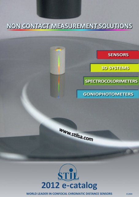
NON CONTACT MEASUREMENT SOLUTIONS<br />
SENSORS<br />
3D SYSTEMS<br />
SPECTROCOLORIMETERS<br />
GONIOPHOTOMETERS<br />
www.stilsa.com<br />
<strong>2012</strong> e-<strong>catalog</strong><br />
WORLD LEADER IN CONFOCAL CHROMATIC DISTANCE SENSORS<br />
E1204
Coming soon<br />
SELECTION<br />
GUIDE<br />
<strong>2012</strong>, A SIGNIFICANT BREAKTROUGH FOR VISION SYSTEM<br />
• CONFOCAL CHROMATIC VISION FOR Automatc Optcal Inspecton: 3D VISION (*)<br />
(*) 3D VISION system combines a real 3D measurement and microscopy image:<br />
- Confocal chromatc measurement in TTL (through the lens),<br />
- High contrast,<br />
- High lateral resoluton,<br />
- Perfect focus in the extended measuring range.<br />
Table of contents<br />
SENSORS<br />
3D SYSTEMS<br />
SPECTRO<br />
COLORIMETERS<br />
GONIO<br />
PHOTOMETERS<br />
Selecton guide<br />
• Selecton guide.................................................................................4<br />
• 3D Metrology products.......................................................................4<br />
Precision class.....................................................................................4<br />
Applicaton type..................................................................................5<br />
Measuring rate.................................................................................6<br />
Scanning mode.................................................................................6<br />
Multi-channel operation......................................................................6<br />
Optical specifications.........................................................................6<br />
Electronic / Software specificatons...............................................................7<br />
Mechanical specificatons.........................................................................7<br />
Value-for-Cost..................................................................................7<br />
Non-contact «point» sensors<br />
• Introducing Chromatc Confocal technology..............................................8<br />
Optcal principle...................................................................................8<br />
Applicatons.......................................................................................9<br />
Product Lines..................................................................................10<br />
• «Bundle» Chromatc Confocal sensors......................................................11<br />
<strong>STIL</strong> Inital sensor line........................................................................11<br />
• Configurable Chromatc Confocal sensors............................................13<br />
The CCS Controller line........................................... .........................13<br />
The CHR Controller line..........................................................................15<br />
Modular optcal pens (CL-MG line)..............................................................18<br />
Classical optcal pens (OP line)...................................................................19<br />
Miniature optcal pens (ENDO line)..............................................................20<br />
• Introducing Spectral Confocal Interferometry technology............................22<br />
Optcal principle...................................................................................22<br />
The DUO controller line..........................................................................23<br />
Interferometric optcal pens (OPILB line)........................................................25<br />
• Fiber optc cables................................................................................26<br />
• Accessories......................................................................................27<br />
• Software...........................................................................................29<br />
4<br />
8<br />
2<br />
www.stlsa.com
SELECTION<br />
GUIDE<br />
SENSORS 3D SYSTEMS<br />
SPECTRO<br />
COLORIMETERS<br />
GONIO<br />
PHOTOMETERS<br />
Table of contents<br />
Non-contact «line» sensors<br />
34<br />
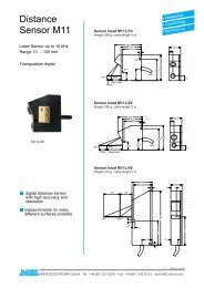
• MPLS180 «line» sensors.........................................................................34<br />
MPLS180 optcal principle.........................................................................34<br />
Basic sensor consttuton..........................................................................35<br />
Optoelectronic controllers: technical specificatons..............................................35<br />
• Optcal heads.....................................................................................36<br />
Non-contact 3D Measurement Systems<br />
• MICROMESURE 2 Systems...................................................................38<br />
Applicatons......................................................................................39<br />
Industrial and Research Laboratories Fields....................................................39<br />
Optons & Accessories...........................................................................39<br />
• Technical specificatons......................................................................39<br />
Scanning system Specificatons.................................................................39<br />
Optoelectronic Controllers Specificatons .....................................................40<br />
Optcal Pens and video camera Specificatons.................................................40<br />
• Software.........................................................................................41<br />
Control and Acquisiton Software Functons....................................................41<br />
Post Processing Software Functons............................................................. 42<br />
38<br />
Non-contact Spectrocolorimeter<br />
• Introducing Colorimetry.........................................................................44<br />
Applicatons..................................................................................... 44<br />
• RUBY Spectrocolorimeter...................................................................44<br />
• Technical specificatons............ ................................................... 45<br />
• Software.......................................................................................46<br />
DLL for RUBY controllers.......................................................................46<br />
RUBY MANAGER software......................................................................47<br />
Goniophotometers<br />
• REFLET introducton and features ....................................... ............. 48<br />
REFLET technical specificatons and applications.......................................... 49<br />
• DIAMOND introducton and applications........................................... 50<br />
• Optons......................................................................................... 51<br />
44<br />
48<br />
Outline dimensions<br />
• Point sensors.................................................................................. 53<br />
• Line sensors...................................................................................68<br />
• Goniophotometers..........................................................................71<br />
52<br />
www.stlsa.com 3
Selecton guide<br />
SELECTION<br />
GUIDE<br />
General selection guide<br />
Application<br />
See<br />
• Measure the Shape of a sample<br />
• Measure the Distance of a sample (auto-focusing)<br />
• Measure the Thickness of a sample or a coating<br />
• Measure the Roughness of a surface<br />
3D Metrology Products<br />
Selecton Guide<br />
(on this page)<br />
SENSORS<br />
• Measure or compare the Color of a sample<br />
• Measure the Spectrum reflected,<br />
transmitted or emitted from a sample or a light source<br />
• Measure the Angular distribution of light beam reflected, transmitted or emitted<br />
from a sample (BRDF/BTDF)<br />
Non Contact spectrocolorimeter<br />
(page 44)<br />
Goniophotometers<br />
(page 48)<br />
3D SYSTEMS<br />
3D Metrology products selection guide<br />
<strong>STIL</strong> SA proposes a large number of products for high quality 3D metrology.<br />
For selectng the right product one should consider several criteria:<br />
• Precision class,<br />
• Applicaton type,<br />
• Measuring rate,<br />
• Scanning mode,<br />
• Mult-channel operaton,<br />
• technical specificatons,<br />
• Value-for-Cost.<br />
SPECTRO<br />
COLORIMETERS<br />
GONIO<br />
PHOTOMETERS<br />
Precision class<br />
Class Axial Resolution (1) Measuring Range Technology Products<br />
Sub-nano-Metrology from 0.3 nm up to 135 µm<br />
Nano-Metrology<br />
from 8.0 nm<br />
(1) Smallest measurable step.<br />
(2) Alone or mounted on a MICROMESURE 3D measuring system.<br />
Several measuring<br />
ranges available:<br />
from 130 µm to<br />
42 mm<br />
CONFOCAL<br />
SPECTRAL<br />
INTERFEROMETRY<br />
(page 22)<br />
CHROMATIC<br />
CONFOCAL<br />
IMAGING<br />
(page 8)<br />
<strong>STIL</strong>-DUO controller (2) with OPILB optcal pen<br />
CCS-PRIMA, <strong>STIL</strong>-INITIAL, <strong>STIL</strong>-DUO or CHR-<br />
150L controller (2) with a CL-MG, OP or Endo<br />
series optcal pen<br />
MPLS 180 sensor<br />
4<br />
www.stlsa.com<br />
E1204
SELECTION<br />
GUIDE<br />
SENSORS 3D SYSTEMS<br />
SPECTRO<br />
COLORIMETERS<br />
GONIO<br />
PHOTOMETERS<br />
Selecton guide<br />
Application type<br />
Application<br />
Products<br />
MEASURING THE SHAPE OR DISTANCE OF A SAMPLE<br />
General case<br />
• A point sensor controller (1)(2) with a CL-MG- series<br />
• MPLS 180 sensor<br />
Long working distance<br />
• CCS-Prima, <strong>STIL</strong>-Duo, CHR-150L controller (2) with a OP- series optcal pen<br />
Inside a cavity (diam. from 7 mm)<br />
• A point sensor controller (1)(2) with a miniature (Endo series) optcal pen<br />
Rough metallic samples<br />
• A point sensor controller (1)(2) with any optcal pen. Optmal performances are achieved with an optcal pen<br />
whose spot size is inferior to 7 µm<br />
• MPLS 180 sensor. Optcal performances are achieved with the Microview optcal head<br />
Mirror-like samples / Low-reflectivity samples<br />
• A point sensor controller (1)(2) with an optcal pen whose photometric efficiency is low / high respectvely<br />
• MPLS 180 sensor.<br />
Sub-Nanometrology applications<br />
(see «precision class»)<br />
• <strong>STIL</strong>-DUO controller (2) with an OPILB- series distance-mode optcal pen<br />
Special requirements (3)<br />
Contact us<br />
MEASURING ROUGHNESS<br />
Measurable Ra:<br />
from 12 nm (with CL1MG210 optcal pen)<br />
from 50 nm (with CL3MG140 optcal pen)<br />
• A point sensor controller (1)(2) with a CL-MG- series or OP- series optcal pen whose spot size is inferior to 7 µm<br />
Sub-nanometric applications<br />
Measurable Ra: from 0.75 nm<br />
• <strong>STIL</strong>-DUO controller (1)(2) with a OPILB- series distance-mode optcal pen<br />
MEASURING THICKNESS<br />
• Measurable Thickness limits:<br />
7.5 µm-175 µm (with CL1MG210 optcal pen)<br />
0.6 mm-34 mm (with CL6MG35 optcal pen)<br />
• A point sensor controller (1)(2) with a CLMG- series or an OP- series optcal pen<br />
• Resolution: 35 nm (with CL1MG210 optcal pen)<br />
Thin films / Very high precision<br />
Measurable Thickness limits: 0.4 µm-90 µm<br />
Resolution: from 0.3 nm<br />
• <strong>STIL</strong>-DUO controller (1)(2) with a OPILB- series thickness-mode optcal pen<br />
(1) Point sensor controller = CCS-Prima, <strong>STIL</strong>-Initial, <strong>STIL</strong>-Duo or CHR-150L controller.<br />
(2) Alone or mounted on a MICROMESURE 3Dmeasuring system.<br />
(3) Measuring through a window or through a coatng, Side-looking optcal pen, Vacuum chamber, Harsh environments, Highly diffusing samples...<br />
E1204<br />
www.stlsa.com 5
Selecton guide<br />
SELECTION<br />
GUIDE<br />
Measuring rate<br />
Ultra-high rate<br />
Requirement Measuring rate Products<br />
Up to 324,000 points/s<br />
(1800 lines/s)<br />
• MPLS 180 sensor<br />
Standard rate<br />
Up to 2,000 points/s<br />
Up to 1,000 points/s<br />
• CCS-Prima, <strong>STIL</strong>-Initial, <strong>STIL</strong>-Duo controllers (*)<br />
• CHR-150L controller (*)<br />
(*) With a suitable optcal pen, alone or mounted on a MICROMESURE 3D measuring system<br />
SENSORS<br />
3D SYSTEMS<br />
Scanning mode<br />
Measuring an area<br />
Requirement Type Products<br />
Measuring a linear or circular profile<br />
Measuring a single point over time<br />
3D<br />
(X,Y,Z)<br />
2D<br />
(X,Z)<br />
1D<br />
(Z)<br />
Multi-channel operation<br />
• MICROMESURE system with any point sensor (*)<br />
• Scanning (3D) MPLS180 sensor<br />
• Static(2D) MPLS180 sensor with the sample on a conveyor belt<br />
• Any point sensor (*) mounted on a user-machine which has at least 2 moton axes<br />
• MICROMESURE system with any point sensor (*)<br />
• Static (2D) MPLS180 sensor<br />
• Any point sensor (*) with the sample on a conveyor belt<br />
• Any point sensor (*) mounted on a user-machine which has at least 1 moton axis<br />
• Any point sensor (*)<br />
(*) Point sensors: CCS-Prima, <strong>STIL</strong>-Duo, <strong>STIL</strong>-Initial or CHR150-L controller with a suitable optcal pen.<br />
Sensor<br />
Multi-channel operation<br />
CHR-150L controller 1,2 or 4 simultaneous channels (1)(2)<br />
SPECTRO<br />
COLORIMETERS<br />
CSS-Prima controller 1,2 or 4 multiplexed channels (1)(3)<br />
<strong>STIL</strong>-Duo controller<br />
<strong>STIL</strong>-Initial controller<br />
MPLS180 sensor<br />
Optical specifications<br />
1 channel for a chromatic confocal optical pen and<br />
1 channel for a interferometric optical pen<br />
The two channels are multiplexed (3)<br />
Single-channel operation only<br />
(1) The number of channels should be specified while ordering, no upgrade is possible later.<br />
(2) Simultaneous channels: all the channels measure at the same tme.<br />
(3) Multplexed channels: all optcal pens may be connected to the controller at the same tme, but only one of them measures.<br />
GONIO<br />
PHOTOMETERS<br />
Optical specifications<br />
• Measuring range<br />
• Axial resolution and accuracy<br />
• Lateral resolution (spot size)<br />
• Working distance<br />
• Maximal measurable slope (°) on specular samples<br />
• Photometric efficiency<br />
• Min/Max measurable thickness<br />
• Min. measurable roughness<br />
See:<br />
• For CCS-Prima, <strong>STIL</strong>-DUO, <strong>STIL</strong>-Initial sensors: See Chromatc Confocal<br />
optcal pen specificatons (Pages 18, 19, 21)<br />
• For <strong>STIL</strong>-Duo sensor: See Interferometric optcal pen specificatons (Pages 26)<br />
• For MPLS180 sensor: See optcal head specificatons (Page 36)<br />
6<br />
www.stlsa.com<br />
E1204
SELECTION<br />
GUIDE<br />
SENSORS 3D SYSTEMS<br />
SPECTRO<br />
COLORIMETERS<br />
GONIO<br />
PHOTOMETERS<br />
Selecton guide<br />
Electronic/Software specifications<br />
Electronic/Software specifications<br />
• Measuring rate<br />
• Digital output type<br />
• Analog outputs<br />
• Trigger options<br />
• Available software<br />
See:<br />
• For Point sensors:<br />
See controller specificatons (Pages 12, 16, 24)<br />
• For MPLS180 sensor:<br />
See controller specificatons (Pages 35)<br />
Mechanical specifications<br />
For Outline dimensions of all products, see pages (53-70).<br />
Value-for-Cost<br />
• The mult-channel point sensors (multplexed CCS-Prima and simultaneous-channel CHR-150L) allow significant saving<br />
compared to 2 or 4 independent sensors.<br />
• The <strong>STIL</strong>-Duo controller combines 2 complementary technologies (Confocal Spectral Interferometry and Chromatic<br />
Confocal Imaging) in the same controller.<br />
• The <strong>STIL</strong>-Initial sensor («bundle» product suitable for first-tme users and for lab applicatons) is proposed at a very attractve<br />
price. This sensor has some limitatons when compared to the other chromatc confocal point sensors as shown<br />
in the table below.<br />
<strong>STIL</strong>-Initial CCS-Prima CHR-150L<br />
Number of optical pens that are interchangeable on<br />
the same controller<br />
1 (1) up to 20 (2) Up to 6 (2)<br />
Available chromatic confocal optical pen models Some models (3) All models All models<br />
Multi-channel operation No Opton (4) Opton (4)<br />
Output type Digital Digital & Analog Digital & Analog<br />
External Encoder reading capability No Yes No<br />
Controller box type Desktop Industrial Desktop<br />
(1) The optcal pen of the <strong>STIL</strong>-Inital is selected when ordering, no replacement is possible later.<br />
(2) Optcal pens may be connected and disconnected from the controller easily. New optcal pens may be added later to the CCS-Prima and the CHR-150L controllers,<br />
but they should be calibrated at factory on the customer’s controller.<br />
(3) See page (11).<br />
(4) See «Mult-channel operaton» on this selecton guide.<br />
E1204<br />
www.stlsa.com 7
Non-contact «point» sensors<br />
SELECTION<br />
GUIDE<br />
SENSORS<br />
Introducing Confocal Chromatic technology<br />
The fruits of more than fifteen years of research and development by<br />
our engineers, <strong>STIL</strong>’s optcal sensors offer the best of technology in<br />
response to the most demanding needs in terms of non contact dimensional<br />
measurements.<br />
Based on an innovatve optcal principle which uses the chromatc coding<br />
of space (invented and patented by <strong>STIL</strong>), our sensors allow users<br />
to make measurements on nearly any kind of materials, with an exceptonal<br />
accuracy.<br />
<strong>STIL</strong>’s sensors find applicatons in almost all sectors of industry, be it as<br />
high precision instruments in metrology or research laboratories, or as<br />
quality control tools on producton lines.<br />
Designed for use in industrial environments, the different ranges of<br />
<strong>STIL</strong>’s sensors will appeal to integrators thanks to their easy interfacing<br />
on measurement and inspecton machines, made possible thanks to<br />
the DLL/ dynamic link libraries provided with each instrument.<br />
3D SYSTEMS<br />
Optical principle<br />
Our optcal sensors are based on the highly innovatve Confocal Chromatc Imaging principle (<strong>STIL</strong> SA’s patent).<br />
SPECTRO<br />
COLORIMETERS<br />
GONIO<br />
PHOTOMETERS<br />
An incident white light pinhole is imaged through a<br />
chromatc objectve into a contnuum of monochromatc<br />
images along the Z-Axis, thus providing a «color coding»<br />
along the optcal axis.<br />
When an object is present in this «colored» field, a<br />
unique wavelength is perfectly focused at its surface<br />
and then reflected into the optcal system.<br />
This backscattered beam passes through a filtering<br />
pinhole into a spectrograph, which determines the<br />
wavelength has been perfectly focused on the object,<br />
and then accurately determine its positon in the<br />
measuring field.<br />
The Confocal Chromatc Imaging gives access to reliable,<br />
accurate and reproducible dimensional measurements<br />
with extremely high resoluton.<br />
8<br />
www.stlsa.com<br />
E1204
SELECTION<br />
GUIDE<br />
SPECTRO<br />
COLORIMETERS<br />
GONIO<br />
PHOTOMETERS<br />
SENSORS 3D SYSTEMS<br />
Non-contact «point» sensors<br />
A wide range of applications<br />
Roughness measurement<br />
Our sensors are fully compliant with<br />
the new ISO25178 regulaton and are<br />
able to measure roughness values<br />
down to a few nanometers.<br />
They allow to acquire roughness profiles<br />
much faster than a classical tactle<br />
probe, and without any risk of marking<br />
the surface.<br />
Profilometry & Microtopography<br />
Interfaced with 3D scanning devices, <strong>STIL</strong>’s sensors<br />
give acess to full 2D and 3D measurements of complex<br />
objects or assemblies with submicronic accuracy.<br />
Thickness measurement<br />
The very innovatve Confocal Chromatc<br />
Imaging principle allows measurement<br />
of the thickness of transparent materials,<br />
with extremely high accuracy,<br />
using one single sensor. The thickness<br />
is directly measured from one<br />
side of the<br />
sample.<br />
Autofocus<br />
Thanks to their extended measuring range, <strong>STIL</strong>’s<br />
sensors are the perfect soluton for an accurate<br />
autofocus in vision systems.<br />
Level control<br />
Thanks to their non-contact technology,<br />
our sensors allow detecton and measurement<br />
of fluids’ level.<br />
Online inspection<br />
<strong>STIL</strong> SA’s optcal sensors allow systematc control<br />
on producton lines thanks to their very high<br />
measuring rates and advanced interfacing<br />
capabilites with the manufacturing<br />
chain or the custom inspecton machine.<br />
Vibrometry<br />
Thanks to very high measuring frequencies and nanometric<br />
resoluton, our sensors allow the measurement<br />
of vibratons in objects under test. Their<br />
non-contact design avoids disturbance of the system<br />
under test, and allows analysis and measurement of<br />
difficult to access areas.<br />
E1204<br />
www.stlsa.com 9
Non-contact «point» sensors<br />
SELECTION<br />
GUIDE<br />
SENSORS<br />
3D SYSTEMS<br />
Characteristics<br />
High resoluton non contact optcal sensors for 3D measurement with a wide range of applicatons.<br />
Advantages<br />
Characteristics<br />
Confocal setup<br />
Coaxial setup<br />
Chromatic coding/decoding<br />
Optical fiber system<br />
Measuring modes<br />
Benefits<br />
- Exceptonal signal-to-noise rato (SNR)<br />
- High resoluton<br />
- No shadowing effects<br />
- Capability of measuring highly polished surfaces<br />
- No Z scanning required<br />
- High precision<br />
- Small, light weight, passive optcal probe («optcal pen»)<br />
connected to the controller by a fiber optcs cable<br />
- «Distance» (Z-coordinate)<br />
- «Thickness» measurement of transparent materials<br />
- Measure on any type of material (metal, glass, ceramics, semiconductors, paper),<br />
- Measure on polished surfaces (mirrors, wafers) and on rough ones,<br />
- Insensitve to ambient lightng,<br />
- Compatble with harsh environments (high temperature / high pressure / irradiaton),<br />
- ISO 25178 standard compliant,<br />
- Large choice of measuring ranges (100 µm to 42 mm ranges),<br />
- Large choice of optcal pens for specific requirements («endoscopic» pens / radial pens / large working distance /<br />
steep slope / small spot size / through-window measurement...),<br />
- Free software toolkit for an easy interfacing («CCS Manager» utlity, c++ and .net DLL SDK).<br />
Product lines<br />
SPECTRO<br />
COLORIMETERS<br />
GONIO<br />
PHOTOMETERS<br />
Product lines<br />
<strong>STIL</strong> Initial<br />
CCS controller<br />
+ Optical pen(s)<br />
+ Fiber optics cable(s)<br />
CHR controller<br />
+ Optical pen(s)<br />
+ Fiber optics cables(s)<br />
Features<br />
- «Bundle» products including everything you need<br />
- Recent design, many advandced features<br />
- Ideal for first-tme users and research laboratories<br />
- Exceptonal Value-for-Price<br />
- Configurable sensors<br />
- Large choice of interchangeable optcal pens<br />
- Recent design, many advandced features<br />
- Ideal for OEM users and Industrial applicatons<br />
- Very wide range of applicatons<br />
- 2 & 4 selectable-channels models available<br />
- Configurable sensors<br />
- Large choice of interchangeable optcal pens<br />
- 2 & 4 simultaneous-channels models available<br />
10<br />
www.stlsa.com<br />
E1204
SELECTION<br />
GUIDE<br />
SPECTRO<br />
COLORIMETERS<br />
GONIO<br />
PHOTOMETERS<br />
SENSORS 3D SYSTEMS<br />
Non-contact «point» sensors<br />
«Bundle» Chromatic Confocal sensors<br />
These sensors measure the alttude (z coordinate) of the sample point located on their optcal axis and the thickness of<br />
transparent samples.<br />
Advantages<br />
- «Bundle» products including everything required for launching a measurement immediately: a controller, an optcal pen<br />
(probe), a fiber optc cable, electrical cables, software tools and a comprehensive user manual,<br />
- Best choice for first-tme users and for research lab applicatons,<br />
- High precision, high resoluton,<br />
- Exceptonal value for price.<br />
<strong>STIL</strong> Initial Sensor Line<br />
<strong>STIL</strong> Inital is a new line of high-resoluton chromatc confocal sensors. 5 models are available, each with a different optcal<br />
pen. Contact us for advice on the best model for your applicaton.<br />
Specifications (*) <strong>STIL</strong> Initial 0.4 <strong>STIL</strong> Initial E1.2 <strong>STIL</strong> Initial E1.2/90 <strong>STIL</strong> Initial 4.0 <strong>STIL</strong> Initial 12<br />
Optical Pen Model CL2-MG140 ENDO 1.2 ENDO 1.2/90° CL4-MG35 CL5-MG35<br />
Measuring Range 0.4 mm 1.2 mm 1.2 mm 4.0 mm 12.0 mm<br />
Working Distance 11.0 mm 2.4 mm 0.4 mm 16.4 mm 29 mm<br />
Axial Resolution 22 nm 100 nm 160 nm 130 nm 400 nm<br />
Accuracy 80 nm 300 nm 800 nm 300 nm 900 nm<br />
(*) See detailed specificatons next page<br />
The <strong>STIL</strong> Inital controller is highly sophistcated, it features extensive synchronizaton opton and advanced measuring modes.<br />
Here are a few examples.<br />
Functions<br />
Application<br />
«Auto-LED» : The LED brightness<br />
adapts itself automatcally<br />
Samples with variable slope e.g lenses<br />
«First peak» : The sensor locks on<br />
the first surface<br />
Topography on transparent objects or<br />
coated samples<br />
«Double Frenquency» : The sensor<br />
selects the optmal measuring rate<br />
automatcally<br />
Samples with high sharp reflectvity variatons,<br />
e.g. mask for microelectronics<br />
«Hold Last Value» : Output data<br />
smoothing<br />
Very difficult samples with many non<br />
measurable points<br />
E1204<br />
www.stlsa.com 11
Non-contact «point» sensors<br />
SELECTION<br />
GUIDE<br />
SENSORS<br />
<strong>STIL</strong> Initial: Technical specifications<br />
Controllers<br />
<strong>STIL</strong> initial Series<br />
Model <strong>STIL</strong> Initial 0.4 <strong>STIL</strong> Initial E1.2 <strong>STIL</strong> Initial E1.2 /90 (1) <strong>STIL</strong> Initial 4.0 <strong>STIL</strong> Initial 12<br />
OPTICAL PEN (PROBE)<br />
Model CL2-MG140 ENDO 1.2 ENDO 1.2/90 (1) CL4-MG35 CL5-MG35<br />
Measuring Range 0.4 mm 1.2 mm 1.2 mm 4.0 mm 12.0 mm<br />
Working Distance 11.0 mm 2.4 mm 0.4 mm 16.4 mm 29 mm<br />
Spot Diameter 3.4 µm 15 µm 13 µm 7.2 µm 16.5 µm<br />
Max. Slope Angle (2) (3) +/- 28° +/- 14° +/- 9° +/- 21° +/- 14°<br />
Weight 190 g 10 g 10g 155 g 175 g<br />
Dimensions x L 27mm x 208.9mm 6 mm x 75.2 mm 6 mm x 82 mm 27 mm x 145.5 mm 27 mm x 145.5 mm<br />
Distance Measurement<br />
Axial Resoluton (4)<br />
- With no averaging<br />
- With Averaging 10<br />
22 nm<br />
8 nm<br />
100 nm<br />
35 nm<br />
160 nm<br />
60 nm<br />
130 nm<br />
50 nm<br />
400 nm<br />
180 nm<br />
Accuracy (5) 80 nm 300 nm 800 nm 300 nm 900 nm<br />
Measuring rough metalic samples (9) R NR NR NR NR<br />
Roughness measurement (10)<br />
Min. measurable Ra<br />
30nm NR NR NR NR<br />
3D SYSTEMS<br />
SPECTRO<br />
COLORIMETERS<br />
GONIO<br />
PHOTOMETERS<br />
Thickness Measurement (6)<br />
Min. Measurable Thickness (7)(8) 16 µm 75 µm NA 110 µm 450 µm<br />
Max. Measurable Thickness (7)(8) 510 µm 1600 µm NA 5700 µm 16500 µm<br />
CONTROLLER BOX<br />
Measuring Modes<br />
Measuring Rate<br />
Digital Outputs<br />
Digital Resoluton<br />
Synchronizaton<br />
Advandced Features<br />
Power supply / Consumpton<br />
Weight<br />
Dimensions W x H x D<br />
FIBER OPTICS CABLE<br />
«Distance» and «Thickness»<br />
100 Hz to 2000Hz<br />
USB 2.0 and RS232 (up to 460800 baud)<br />
In «Distance» mode: 30 bits<br />
In «Thickness» mode: 15 bits<br />
Input and Output 0V - 5V TTL synchronizaton signals<br />
Extensive trigger capacites<br />
«Double frequency» mode<br />
«Auto LED» mode<br />
«First peak» mode<br />
«Hold last value» mode<br />
«Thickness calibraton»<br />
100V to 240 V AC 50-60 Hz / 25W<br />
1920 g<br />
199 mm x 123.5 mm x 277 mm<br />
(1) Radial (90°) measuring optcal pen.<br />
(2) The maximal angular slope applies to specular (mirror-like) surfaces only. For Diffusing surfaces the maximal slope angle is higher (up to 87° for perfect diffusers).<br />
(3) Measured on a mirror at 100 Hz, with no averaging.<br />
(4) Axial resoluton is defined as the RMS Noise level measured at optmal rate on a statc sample located at the center of the measuring, with no averaging.<br />
(5) Accuracy is defined as the max. error over the entre measuring range, measured immediately after distance calibraton at the following conditons: “Auto-adaptve LED”<br />
mode, optmal rate, slope angle=0°, averaging factor= measuring rate/10.<br />
(6) For obtaining metrological performances in this mode it is recommended to carry out a calibraton on a thickness standard.<br />
(7) These values are for a refractve index of 1.5 (for measuring air gap thickness divide by 1.5).<br />
(8) Typical values, measured at the center of the measuring range at optmal rate, with no averaging.<br />
(9) R = Recommended for measuring rough metallic samples (these samples can be measured with full performances)<br />
NR = Not recommended for measuring rough metallic samples (these samples may be measured, but with reduced performances)<br />
(10) The precise value of the min measurable Ra depends on the characteristcs of the sample. The values given in the table are typical..<br />
N.B. : the values are subject to change without notce.<br />
12<br />
www.stlsa.com<br />
E1204
SELECTION<br />
GUIDE<br />
SPECTRO<br />
COLORIMETERS<br />
GONIO<br />
PHOTOMETERS<br />
SENSORS 3D SYSTEMS<br />
Non-contact «point» sensors<br />
Configurable Chromatic Confocal «point» sensors<br />
These sensors measure the alttude (z coordinate) of the sample point located on their optcal axis.<br />
They can also measure the thickness of transparent samples.<br />
They consist of a controller (1), an «optcal pen» (optcal probe) (2) and a fiber optc cable (3).<br />
2 controller lines (CCS & CHR), 3 optcal pen lines (CL-MG, OP & ENDO) and different fiber optc cable models are available.<br />
A single controller may be ordered with several interchangeable optcal pens.<br />
(1)<br />
(3)<br />
(2)<br />
Advantages<br />
- Select the CCS or CHR controller, as well as the optcal pen and the fiber optcs cable best suited for your applicaton.<br />
- Large choice of measuring ranges (110 µm - 20 mm),<br />
- Large choice of optcal pens satsfying specific requirements («endoscopic» / radial pens / large working distance / steep<br />
slope / small spot size / through-window measurement..)<br />
The CCS controller line<br />
3 controllers for configurable chromatc confocal sensors featuring different number of channels are available:<br />
- the CCS PRIMA (1 channel), CCS PRIMA 2 (2 channels) and CCS PRIMA 4 (4 channels).<br />
Advantages<br />
- High precision, high resoluton,<br />
- Compatble with all chromatc confocal optcal pens,<br />
- Up to 20 different optcal pens interchangeable on the same controller,<br />
- Digital and analog outputs,<br />
- Synchronized reading of external digital encoders.<br />
CCS PRIMA controllers<br />
- The leading chromatic confocal sensor worldwide,<br />
- The most sophisticated chromatic confocal sensor on the market,<br />
- Recommended for OEM User and Industrial applicatons,<br />
- Improved performances in thickness mode thanks to a specific Thickness calibraton,<br />
- Long lifetme light source,<br />
- Measuring rates: 100 Hz to 2000 Hz.<br />
E1204<br />
www.stlsa.com 13
SPECTRO<br />
COLORIMETERS<br />
Non-contact «point» sensors<br />
SELECTION<br />
GUIDE<br />
The CCS PRIMA controller is higly sophistcated, it offers extensive synchronizaton optons and advanced measuring modes.<br />
SENSORS<br />
Functions<br />
«Auto-LED» : The LED brightness<br />
adapts itself automatcally<br />
«First peak» : The sensor locks on<br />
the first surface<br />
«Double Frenquency» : The sensor<br />
selects the optmal measuring rate<br />
automatcally<br />
«Hold Last Value» : Output data<br />
smoothing<br />
Application<br />
Samples with variable slope e.g lenses<br />
Topography on transparent objets<br />
Samples with high sharp reflectvity<br />
variatons, e.g. mask for microelectronics<br />
Very difficult samples with many non<br />
measurable points<br />
3D SYSTEMS<br />
2 and 4 CCS Prima Multiplexed Channel Models<br />
- Up to 4 optcal pens connected to a single CCS PRIMA controller<br />
- Multplexed channels, Commutaton tme < 400ms,<br />
- Ideal for automatc inspecton applicatons,<br />
- Save up to 62 % compared to 4 independent controllers.<br />
GONIO<br />
PHOTOMETERS<br />
4 multplexed channels<br />
CCS PRIMA4 Controller<br />
2 multplexed channels<br />
CCS PRIMA2 Controller<br />
14<br />
www.stlsa.com<br />
E1204
SELECTION<br />
GUIDE<br />
SPECTRO<br />
COLORIMETERS<br />
GONIO<br />
PHOTOMETERS<br />
SENSORS 3D SYSTEMS<br />
Non-contact «point» sensors<br />
The CHR Controller Line<br />
CHR150-L controllers<br />
- High precision, high resoluton,<br />
- Measuring rate up to 1 KHz,<br />
- Compatble with all optcal pens,<br />
- Long lifetme light source,<br />
- Intergrated control panel.<br />
CHR150 controllers<br />
- Tungsten Halogen light source<br />
2 and 4 CHR150 or CHR150-L simultaneous channel models<br />
- Up to 4 optcal pens connected to a single CHR150-L controller<br />
- All channels measure simultaneously,<br />
- Each channel may be configured independently,<br />
- Save up to 44% compared to 4 independent controllers.<br />
2 Channels CHR150 Controller<br />
E1204<br />
www.stlsa.com 15
Non-contact «point» sensors<br />
SELECTION<br />
GUIDE<br />
Controllers for configurable chromatic confocal point sensors:<br />
Technical specifications<br />
Controllers CHR Series CCS Series<br />
Model CHR150 CHR150-L CCS-PRIMA<br />
Measuring frequency<br />
From 30 to 1000 points/sec<br />
User defined<br />
From 30 to 1000 points/sec<br />
User defined<br />
From 100 to 2000 points/sec<br />
User defined<br />
Multchannel version (1) Available (2 & 4 channels) Available (2 & 4 channels) Available (2 &4 channels)<br />
SENSORS<br />
Light source Halogen White LED White LED<br />
Light source brightness setting None Manual Programmable<br />
Advandced Features:<br />
«Lock on first surface»<br />
«Hold Last Value»<br />
«Thickness calibraton»<br />
«Auto LED» (2)<br />
«Autodark» functon (3)<br />
«Double frequency»<br />
No<br />
No<br />
No<br />
No<br />
No<br />
Up to 489 Hz<br />
No<br />
No<br />
No<br />
No<br />
No<br />
Up to 489 Hz<br />
Yes<br />
Yes<br />
Yes<br />
Yes<br />
Yes<br />
Up to 1850 Hz<br />
Measuring modes<br />
Distance<br />
Thickness<br />
Distance<br />
Thickness<br />
Distance<br />
Thickness<br />
Calibraton tables (max) 6 20<br />
3D SYSTEMS<br />
SPECTRO<br />
COLORIMETERS<br />
GONIO<br />
PHOTOMETERS<br />
Encoders input (4) No No Yes (up to 3 axes) - TTL signals input - 30 bits counters (> 1 billion steps count)<br />
Digital outputs 15 bits resoluton 30 bits resoluton<br />
Analog outputs 2 configurable outputs [0 – 10 V] - 12 bits resoluton 2 configurable outputs [0 - 10V] - 16 bits resoluton<br />
Digital I/O RS232 (up to 115200 baud») serial link USB2 and RS232/RS422 (up to 46800 baud)<br />
Synchronizaton I/O 1 Synchro input (TTL) / 1 Synchro output (TTL) 1 Synchro input (TTL) / 1 Synchro output (TTL)<br />
Optcal fiber connector<br />
Compatble Optcal pens<br />
E2000 type («push-pull») with «Autoprotect» system<br />
All chromatc confocal pen types<br />
Power supply / consumpton From 85 to 240 V AC / 100 W From 85 to 240 V AC / 25 W 24 V DC / 20 W<br />
Temperature in use 5°C - 40°C<br />
Storage temperature -30°C – 70°C<br />
Relatve humidity in use<br />
5%-80% HR without condensaton<br />
Protecton type IP 40<br />
EMC<br />
EN 61000-6-3 and EN 61000-6-2 compliant<br />
Weight (5) 3.4 kg 1.4 Kg<br />
Dimensions (w x h x d) 316mm x 96mm x 235mm 168mm x 138mm x 120mm<br />
Mechanical interface Table top controller Integrated DIN rail mountng interface<br />
(1) Multplexed channels (CCS) Vs simultaneous multple channels (CHR):<br />
- CCS PRIMA4 multplexed sensor: 1 (out of 4) optcal pen can measure at a tme, the sensor can switch to another optcal<br />
pen in about 400 ms.<br />
- CHR150-2 and CHR150-4 Multple channels: All the optca l pens (2 or 4) can measure simultaneously.<br />
(2) The «Auto Led» functon allows the CCS Prima controller to dynamically adjust the LED light power in order to permanently adapt<br />
it according to the reflectvity of the measured object.<br />
(3) The «Autodark» functon allows a constant and automatc regulaton of the Dark signal level of the CCS controller.<br />
(4) The incremental encoders input port allows the acquisiton of the instant positon of the measuring system moton axes (3 axes<br />
maximum). These measurements are synchronized with the measuring frequency of the sensor.<br />
(5) The specified weight does not include the external light source for the CCS Ultma model.<br />
N.B. : the values are subject to change without notce.<br />
16<br />
www.stlsa.com<br />
E1204
SELECTION<br />
GUIDE<br />
SPECTRO<br />
COLORIMETERS<br />
GONIO<br />
PHOTOMETERS<br />
SENSORS 3D SYSTEMS<br />
Non-contact «point» sensors<br />
3D measurement examples: chromatic confocal technology<br />
Intra occular lens (IOL) - Z range: 750µm<br />
3D measurement examples: confocal spectral interferometry<br />
Through Silicon Vias (TSV) array - Via diameters: 5µm to 20µm - Z range 100µm<br />
E1204<br />
www.stlsa.com 17
Non-contact «point» sensors<br />
SELECTION<br />
GUIDE<br />
Modular optical pens (CL-MG Line)<br />
CL-MG Line *<br />
Model CL1 CL2 CL3 CL4 CL5 CL6<br />
Measuring range (1) [µm] 130 400 1400 4000 12000 24000<br />
Working distance (2) [mm] 3.3 11 12.7 16.4 29 22<br />
Max. object slope (3) [deg] +/- 42.5° +/- 28° +/- 25° +/- 21° +/- 14° +/- 8.5°<br />
Reference plate (4) - No Yes Yes Yes Yes No<br />
SENSORS<br />
Axial model (5)<br />
-<br />
Radial model (5) -<br />
Standard<br />
Optonal<br />
Magnifier model MG210 MG140 MG210 MG140 MG70 MG140 MG70 MG35 MG20 MG35 MG20 MG35 MG20<br />
LATERAL (XY) PROPERTIES<br />
Spot size (diameter)<br />
Lateral resoluton (6)<br />
[µm]<br />
[µm]<br />
1.9<br />
0.9<br />
2.8<br />
1.4<br />
2.3<br />
1.2<br />
3.4<br />
1.7<br />
6.9<br />
3.5<br />
4<br />
2<br />
8<br />
4<br />
8<br />
4<br />
14<br />
7<br />
14<br />
7<br />
24.5<br />
12.3<br />
16<br />
8<br />
28<br />
14<br />
PHOTOMETRIC EFFICIENCY (7)<br />
Collected energy (relatve) - 5.8 13 5.5 11.5 46 14 56 30 76 40 100 19.2 48<br />
3D SYSTEMS<br />
SPECTRO<br />
COLORIMETERS<br />
MECHANICAL INTERFACE<br />
Length (8)<br />
Diameter (8)<br />
Weight<br />
Performances (9)<br />
DISTANCE MEASUREMENT<br />
Axial resoluton (10)<br />
With no averaging<br />
With averaging 10<br />
Accuracy (11)<br />
Measuring rough metal surface (12)<br />
[mm]<br />
[mm]<br />
[g]<br />
[nm]<br />
[nm]<br />
[nm]<br />
-<br />
253.1<br />
27<br />
268<br />
8<br />
2.7<br />
35<br />
R<br />
217.1<br />
27<br />
195<br />
243.3<br />
27<br />
248<br />
208.9<br />
27<br />
190<br />
22<br />
8<br />
80<br />
R<br />
ROUGHNESS MEASUREMENT<br />
Min. measurable Ra (13) [nm] 12 30 90 170 600 1100<br />
THICKNESS MEASUREMENT (14)<br />
Min. measurable thickness (15)<br />
Max. measurable thickness (15)<br />
[µm]<br />
[µm]<br />
7.5<br />
175<br />
9<br />
175<br />
14<br />
510<br />
14<br />
510<br />
176.1<br />
27<br />
189<br />
22<br />
510<br />
205.9<br />
27<br />
215<br />
R<br />
38<br />
2000<br />
60<br />
20<br />
200<br />
176.1<br />
27<br />
214<br />
NR<br />
40<br />
2000<br />
145.5<br />
27<br />
155<br />
110<br />
5700<br />
130<br />
50<br />
300<br />
NR<br />
131.7<br />
27<br />
140<br />
120<br />
5700<br />
145.5<br />
27<br />
175<br />
350<br />
16500<br />
400<br />
180<br />
800<br />
NR<br />
131.7<br />
27<br />
160<br />
550<br />
16500<br />
167.6<br />
27<br />
195<br />
590<br />
34000<br />
780<br />
300<br />
1500<br />
NR<br />
151.8<br />
27<br />
180<br />
725<br />
34000<br />
GONIO<br />
PHOTOMETERS<br />
N.B. : the values are subject to change without notce.<br />
18<br />
www.stlsa.com<br />
E1204
SELECTION<br />
GUIDE<br />
SENSORS 3D SYSTEMS<br />
SPECTRO<br />
COLORIMETERS<br />
GONIO<br />
PHOTOMETERS<br />
Non-contact «point» sensors<br />
Classical optical pens (OP Line)<br />
OP Line<br />
Model OP300VM OP6000 OP8000 OP10000 OP24000 OP42000<br />
Measuring range (1) [µm] 300 6 000 8000 10 000 24 000 42 000<br />
Working distance (2) [mm] 5 28.8 37.2 66.9 223 518<br />
Max object slope (3) [deg] +/- 25° +/- 22° +/- 16° +/- 12° +/- 5° +/- 2.5°<br />
Reference plate (4) - No No Yes Yes Yes No<br />
Axial model (5)<br />
Radial model (5) -<br />
Standard<br />
Optonal<br />
Standard<br />
No<br />
Standard<br />
No<br />
Standard<br />
Optonal<br />
Standard<br />
Optonal<br />
Standard<br />
No<br />
LATERAL (XY) PROPERTIES<br />
Spot size (diameter)<br />
Lateral resoluton (6)<br />
[µm]<br />
[µm]<br />
8<br />
4<br />
12.5<br />
6.25<br />
34<br />
17<br />
51<br />
25.5<br />
100<br />
50<br />
110<br />
55<br />
MECHANICAL INTERFACE<br />
Length (8)<br />
Diameter (8)<br />
Weight<br />
[mm]<br />
[mm]<br />
[g]<br />
127<br />
15<br />
25<br />
205.5<br />
60<br />
727<br />
150<br />
40<br />
400<br />
189<br />
50<br />
640<br />
172.5<br />
59<br />
360<br />
287.2<br />
85<br />
1700<br />
Performances (9)<br />
DISTANCE MEASUREMENT<br />
Axial resoluton (10)<br />
Accuracy (11)<br />
[nm]<br />
[nm]<br />
10<br />
90<br />
250<br />
600<br />
400<br />
800<br />
450<br />
900<br />
1500<br />
3000<br />
4000<br />
40000<br />
Min. measurable thickness (15) [µm] 25 200 300 425 1570 2500<br />
(1) The measuring range depends on the controller model. The numerical values in this table are nominal values for a CCS Prima controller.<br />
(2) The working distance depends on the controller model. The numerical values given in this table are typical values for a CCS-Prima controller.<br />
(3) The max measurable slope angle applies to specular (mirror-like) surfaces only. For scattering surfaces the maximal slope angle is higher (up to 87° for perfect diffusers); however<br />
the intensity of the collected signal decreases with increasing slope angle. The values given in this table were measured on a mirror at a rate of 100 Hz, with no averaging.<br />
(4) The reference plate is a glass window that can be either located inside the optcal pen, or fixed on the same surface.<br />
(5) For “axial” optcal pens the measuring range is parallel to the mechanical axis of the pen.<br />
For “radial” optcal pens the measuring range is normal to the mechanical axis, allowing to measure inside holes.<br />
(6) The lateral resoluton is defined as half the spot diameter.<br />
(7) The photometric efficiency is the amount of energy collected by different optcal pens when measuring the same sample, in relatve units. The numerical values in this table are<br />
typical, they are given only as a guide for selectng the magnifier model: For measuring a highly-reflectng sample, select a model with low photometric efficiency in order to avoid<br />
saturaton. For measuring diffusive or low-reflectng samples, select a model with high photometric efficiency in order to avoid a poor signal-to-noise rato.<br />
(8) Length and weight excluding the fiber optcs cable. The values given here are for the “axial” model.<br />
(9) The performances given in this table were measured for a CCS Prima controller.<br />
(10) Axial resoluton is defined as the RMS noise level measured on a statc sample. Measurement is performed at optmal rate on a sample located at the center of the measuring<br />
range. Two values are given, with internal averaging set to 1 and to 10, respectvely. This parameter is measured immediately after distance calibraton and is specified on the<br />
calibraton certficate which is delivered with each sensor.<br />
(11) The accuracy is the max error observed in the entre measuring range when comparing the distance measured by the sensor with sample positon determined by a 1-nm<br />
accurate encoder. This parameter is measured with the following settings: “Auto-adaptve LED” mode, optmal rate, slope angle=0°, internal averaging = measuring rate/10.<br />
This parameter is measured immediately after distance calibraton and is specified on the calibraton certficate which is delivered with each sensor.<br />
(12) R = Recommended for measuring rough metallic samples (these samples can be measured with full performances)<br />
NR = Not recommended for measuring rough metallic samples (these samples may be measured, but with reduced performances)<br />
(13) The precise value of the min measurable Ra depends on the characteristcs of the sample. The values given in the table are typical.<br />
(14) Performances in thickness mode, and in partcular the accuracy of thickness measurement, depend on the characteristcs of the sample as well as on a procedure of “Thickness<br />
calibraton” that should be performed by the user. For more informaton contact us.<br />
(15) Typical values measured at the center of the measuring range at optmal rate, with no averaging.<br />
These values are for a sample with a refractve index = 1.5 (When measuring the thickness of an air-gap they should be divided by 1.5)<br />
N.B. : the values are subject to change without notce.<br />
E1204<br />
www.stlsa.com 19
Non-contact «point» sensors<br />
SELECTION<br />
GUIDE<br />
Miniature optical pens (ENDO Line)<br />
SENSORS<br />
3D SYSTEMS<br />
<strong>STIL</strong> introduce ENDO, a new line of confocal chromatc pens providing an amazing tny size.<br />
The ENDO optcal pens are ideal for non-contact measurements applicaton in reduced space environnements.<br />
These miniature pens are very useful fot the measurement of holes or cavites with small diameter.<br />
Thanks to their small size (6 mm diameter), their integraton in inspecton machines in the producton line is made easier.<br />
SPECTRO<br />
COLORIMETERS<br />
Working with any <strong>STIL</strong> optoelectronic controllers, the ENDO series allow performing a precise measurement with submicron resoluton.<br />
GONIO<br />
PHOTOMETERS<br />
Axial measuring directon configuraton<br />
20<br />
www.stlsa.com<br />
E1204
SELECTION<br />
GUIDE<br />
SPECTRO<br />
COLORIMETERS<br />
GONIO<br />
PHOTOMETERS<br />
SENSORS 3D SYSTEMS<br />
Non-contact «point» sensors<br />
Miniature Series<br />
Model ENDO0.1 ENDO0.3/90 ENDO1.2 ENDO1.2/90 ENDO1.5 ENDO1.5/90<br />
Nominal measuring range (1) [µm] 100 300 1200 1200 1500 1500<br />
Working distance [mm] 1.1 0.8 2.3 0.4 2.1 0.5<br />
Minimum radius measurable (2) [mm] - 3.8 - 3.4 - 3.5<br />
Axial resoluton in distance mode [µm] 0.02 * 0.1 0.15 0.1 *<br />
Axial accuracy in distance mode [µm] 0.05 * 0.2 0.25 0.2 *<br />
Max object slope (3) [deg] +/-24° +/-10° +/- 13° +/- 11° +/- 13° +/- 10°<br />
Spot size diameter [µm] 6.2 6 15 15 7.1 20<br />
Lateral resoluton [µm] 3.1 3 7.5 7.5 3.5 10<br />
Length (4) [mm] 58.9 69.8 75.2 82 100.6 90<br />
Weight (4) [g] 10 * 10 10 12 12<br />
Mechanical diameter [mm] 6 6 6 6 6 6<br />
Measuring directon - Axial Radial Axial Radial Axial Radial<br />
(1) The precise values of the measuring range, the resoluton and the working distance depend on the controller type. The values in these tables are for the<br />
CCS PRIMA controller.<br />
(2) The minimum radius measurable is the distance from the axial axis to the beginning of the measuring range for radial configuraton.<br />
(3) The values in these tables are for specular samples, for diffusive samples, the maximum slope can be much higher. The values are theoretcal.<br />
(4) The length and weight do not include the optcal fiber.<br />
(*) These parameters will be soon available, contact us.<br />
Radial measuring directon configuraton (zoom)<br />
N.B. : the values are subject to change without notce.<br />
E1204<br />
www.stlsa.com 21
GONIO<br />
PHOTOMETERS<br />
Non-contact «point» sensors<br />
SELECTION<br />
GUIDE<br />
SENSORS<br />
Introducing Spectral Confocal Interferometry technology<br />
The measurement accuracy in non contact profilometric techniques is generally limited by mechanical vibratons and by positonal<br />
inaccuracies of the micro-scanning table. In order to free the measurement from these environnemental perturbatons, <strong>STIL</strong> has<br />
developed a new vibraton insensitve interferometric method. With this new type of interferometric system, the potental subnanometric<br />
accuracy of interferometric microscopy is effectve.<br />
Moreover this new sensor can be used for measuring transparent films that are too thin to allow the “Chromatc Confocal” technique<br />
to be used. The minimum measurable thickness is 0.4 µm.<br />
3D SYSTEMS<br />
SPECTRO<br />
COLORIMETERS<br />
Confocal Spectral Interferometry principle<br />
The <strong>STIL</strong> interferometric method is based on Spectroscopic Analysis of White Light Interferograms (SAWLI). It consists in analysing<br />
the interference signal observed on a spectrometer in order to measure the air gap thickness between the reference plate and the<br />
sample. The originality of the developed system lies in the fixaton of the reference plate on the inspected object. As reference<br />
plate and sample are fixed together, the mechanical vibratons do not affect the measurements.<br />
The interferometric signal is a channelled spectrum. From this signal, the spectral phase is calculated using a numerical seven<br />
points phase shifting algorithm allowing the measurement of the local height of the analyzed surface with a subnanometric<br />
resoluton.<br />
22<br />
www.stlsa.com<br />
E1204
SELECTION<br />
GUIDE<br />
SPECTRO<br />
COLORIMETERS<br />
GONIO<br />
PHOTOMETERS<br />
SENSORS 3D SYSTEMS<br />
Non-contact «point» sensors<br />
The <strong>STIL</strong> DUO controller line<br />
The new sensor <strong>STIL</strong> DUO double technology, a new standard in the world of dimensional measurement.<br />
The sensor <strong>STIL</strong> DUO is the first system in the world that offers two simultaneous measurement technologies: the Confocal<br />
Chromatc and the White Light Spectral Interferometry with an original confocal setup.<br />
By associatng these two technologies (two <strong>STIL</strong> processes) the sensor <strong>STIL</strong> DUO creates a new standard in the world of dimensional<br />
measurement because it allows the user to get the very best out of these two operatng principles:<br />
- <strong>STIL</strong>’s Confocal Chromatc principle makes it possible to work with a large measurement scale going from 130 µm<br />
to 42 mm. This characteristc is perfect for rugosity and surface topography measurements, which give very high<br />
precision results on any type of material, be it reflectve or diffusing. The measurement is in compliance with the<br />
new ISO 25178 standard.<br />
- <strong>STIL</strong>’s Confocal Spectral Interferometry process gives access to sub-nanometric resolutons (
GONIO<br />
PHOTOMETERS<br />
Non-contact «point» sensors<br />
SELECTION<br />
GUIDE<br />
SENSORS<br />
Advantages<br />
- Vibraton insensitve (OPILB-RP optcal pen),<br />
- High signal to noise rato (OPILB-RP optcal pen),<br />
- No vertcal scanning required,<br />
- Minimum measurable thickness 0.4 µm,<br />
- Subnanometric resoluton inherent to the optcal principle,<br />
- No cross talk between neighbouring points, thanks to confocality,<br />
- Exceptonnal performances in thickness measurement (0.3 nm resoluton, 10 nm accuracy)<br />
Configurations<br />
The sensor consists of:<br />
- A <strong>STIL</strong> DUO controller,<br />
- One or more interference optcal pen(s),<br />
- One or more chromatc confocal optcal pen(s) (optonal),<br />
- a fiber optc cable for each optcal pen.<br />
3D SYSTEMS<br />
<strong>STIL</strong>-DUO controller: technical specifications<br />
DUO<br />
Measuring frequency<br />
up to 2000 Hz<br />
Wavelength range<br />
400-900 nm<br />
Spectral resoluton<br />
0.6 nm / pixel<br />
SPECTRO<br />
COLORIMETERS<br />
Light Source<br />
Digital outputs<br />
Synchronizaton I/O<br />
Optcal fiber connectors<br />
Humidity limits<br />
Temperature in use<br />
Dimensions<br />
Weigth<br />
Measuring mode:<br />
Distance/Thickness<br />
Tungsten halogen lamp and White LED<br />
Ethernet / RS232<br />
1 input (TTL) / 1 output (TTL)<br />
E2000<br />
5%-80% HR without condensaton<br />
5 - 50° C<br />
376mm x 363mm x 114mm<br />
6 Kg<br />
1- Confocal Chromatc<br />
2- Confocal spectral Interferometry<br />
24<br />
www.stlsa.com<br />
E1204
SELECTION<br />
GUIDE<br />
SENSORS 3D SYSTEMS<br />
SPECTRO<br />
COLORIMETERS<br />
GONIO<br />
PHOTOMETERS<br />
Non-contact «point» sensors<br />
Interferometric optical pens (OPILB line)<br />
OPILB Line<br />
Model OPILB-RP OPILB-LWD-D OPILB-LWD-T OPILB<br />
Measuring mode - Distance Distance Thickness Thickness<br />
Measuring range [µm] 135 135 - -<br />
Working distance [mm] 5.3 5.3 5.3 42<br />
Max. object slope [deg] +/- 7° +/- 7° +/- 7° +/- 7°<br />
Reference plate (1) - Yes No No No<br />
Magnifier model MG210 MG140 MG210 MG140 MG70 MG35 MG20 -<br />
LATERAL (XY) PROPERTIES<br />
Spot size (diameter)<br />
Lateral resoluton (2)<br />
[µm]<br />
[µm]<br />
3.8<br />
1.9<br />
5.6<br />
2.8<br />
3.8<br />
1.9<br />
5.6<br />
2.8<br />
11.4<br />
5.7<br />
22.8<br />
11.4<br />
40<br />
20<br />
40<br />
20<br />
MECHANICAL INTERFACE<br />
Length (4)<br />
Diameter (4)<br />
Weight<br />
[mm]<br />
[mm]<br />
[g]<br />
200<br />
27<br />
200<br />
164<br />
27<br />
127<br />
200<br />
27<br />
200<br />
164<br />
27<br />
127<br />
131<br />
27<br />
126<br />
100<br />
27<br />
67<br />
84<br />
27<br />
52<br />
145.5<br />
27<br />
155<br />
Performances<br />
DISTANCE MEASUREMENT<br />
Axial resoluton (5)<br />
Accuracy (6)<br />
Measuring rough metal surface (7)<br />
[nm]<br />
[nm]<br />
-<br />
0.5<br />
10<br />
NR<br />
2<br />
10<br />
NR<br />
- -<br />
ROUGHNESS MEASUREMENT<br />
Min. measurable Ra (8) [nm] 0.5 3 - -<br />
THICKNESS MEASUREMENT<br />
Min. measurable thickness (9)<br />
Max. measurable thickness (9)<br />
Axial resoluton (5)<br />
Accuracy (6)<br />
[µm]<br />
[µm]<br />
[nm]<br />
[nm]<br />
-<br />
-<br />
-<br />
-<br />
-<br />
-<br />
-<br />
-<br />
-<br />
-<br />
-<br />
-<br />
-<br />
-<br />
-<br />
-<br />
0.4<br />
90<br />
0.3<br />
10<br />
0.4<br />
90<br />
0.3<br />
10<br />
0.4<br />
90<br />
0.3<br />
10<br />
0.4<br />
90<br />
0.3<br />
10<br />
(1) The reference plate is placed directly on the sample. The reference plate of the OPILB-RP acts as an absolute reference. It compensates for the mechanical imperfectons<br />
of the scanning system.<br />
(2) The lateral resoluton is defined as half the spot diameter.<br />
(3) The photometric efficiency is the amount of energy collected by different optcal pens when measuring the same sample, in relatve units. The numerical values in this<br />
table are typical, they are given only as a guide for selectng the magnifier model: For measuring a highly-reflectng sample, select a magnifier model with low photometric<br />
efficiency in order to avoid saturaton. For measuring diffusive or low-reflectng samples, select a magnifier with high photometric efficiency in order to avoid a poor<br />
signal-to-noise rato.<br />
(4) Length and weight excluding the fiber optcs cable.<br />
(5) Axial resoluton is defined as the RMS noise level measured on a statc sample. Measurement is performed at optmal rate on a sample located at the optmal poston.<br />
(6) The accuracy is the max error observed in the entre measuring range when comparing the distance measured by the sensor with sample positon determined by a<br />
1-nm accurate encoder.<br />
(7) R = Recommended for measuring metallic samples (these samples can be measured with full performances)<br />
NR = Not recommended for measuring metallic samples (these samples may be measured, but with reduced performances)<br />
(8) The precise value of the min measurable Ra depends on the characteristcs of the sample. The values given in the table are typical.<br />
(9) These values are for a sample with a refractve index = 1.5 (When measuring the thickness of an air-gap they should be multplied by 1.5)<br />
E1204<br />
www.stlsa.com 25
Non-contact «point» sensors<br />
SELECTION<br />
GUIDE<br />
SENSORS<br />
Fiber optic cables<br />
E2000 «push/pull» connector<br />
Model Length Core Ø Ø max Sheath Connector type<br />
E50-3 3 m 50/125 µm 2.8 mm Standard E2000<br />
E50-5 5 m 50/125 µm 2.8 mm Standard E2000<br />
E50-10 10 m 50/125 µm 2.8 mm Standard E2000<br />
E20-2 2 m 10/20 µm 1.9 mm Standard E2000<br />
E50-3-M 3 m 50/125 µm 5 mm Metal armored E2000<br />
E50-5-M 5 m 50/125 µm 5 mm Metal armored E2000<br />
E50-10-M 10 m 50/125 µm 5 mm Metal armored E2000<br />
E50-20-M 20 m 50/125 µm 5 mm Metal armored E2000<br />
3D SYSTEMS<br />
SPECTRO<br />
COLORIMETERS<br />
Standard E2000 connector optcal fiber<br />
Metallic armored E2000 connector optcal fiber<br />
FC/APC connector<br />
Model Length Core Ø Ø max Sheath Connector type<br />
F50-3 3 m 50/125 µm 2.8 mm Standard FC/APC<br />
F50-4 4 m 50/125 µm 2.8 mm Standard FC/APC<br />
F50-10 10 m 50/125 µm 2.8 mm Standard FC/APC<br />
F20-2 2 m 10/20 µm 1.9 mm Standard FC/APC<br />
F50-3-M 3 m 50/125 µm 5 mm Metal armored FC/APC<br />
F50-4-M 4 m 50/125 µm 5 mm Metal armored FC/APC<br />
F50-10-M 10 m 50/125 µm 5 mm Metal armored FC/APC<br />
F20-4-M 4 m 10/20 µm 5 mm Metal armored FC/APC<br />
F20-10-M 10 m 10/20 µm 5 mm Metal armored FC/APC<br />
F50-5-M 5 m 10/20 µm 5 mm Metal armored FC/APC<br />
F50-10-M 10 m 10/20 µm 5 mm Metal armored FC/APC<br />
GONIO<br />
PHOTOMETERS<br />
Standard FC/APC connector optcal fiber<br />
Metallic armored FC/APC connector optcal fiber<br />
26<br />
www.stlsa.com<br />
E1204
SELECTION<br />
GUIDE<br />
SPECTRO<br />
COLORIMETERS<br />
GONIO<br />
PHOTOMETERS<br />
SENSORS 3D SYSTEMS<br />
Non-contact «point» sensors<br />
Accessories<br />
Mechanical accessories<br />
Model<br />
ST3<br />
DT3x3<br />
Description<br />
Single turreti<br />
Mechanical assembly allowing to combine one magnifier with three different chromatc lenses.<br />
Double turreti<br />
Mechanical assembly allowing to combine three magnifiers with three different chromatc lenses.<br />
The new concept of Modular Optcal Pen (consistng of the combinaton of a<br />
chromatc objectve and an achromatc magnifier) offers the major opportunity<br />
to design a more flexible combinaton : the MULTIPEN which can be available in<br />
two different configuratons : ST and DT.<br />
Based on a microscope turret, the MULTIPEN ST consists of the combinaton of<br />
one achromatc magnifier with three different chromatc lenses, thus offering<br />
three different depths of field in one single mechanical assembly.<br />
The MULTIPEN DT (for double turret) comprises a second turret equipped with<br />
three different magnifiers, thus offering three different spot sizes for each of<br />
the three chromatc objectves. This corresponds to nine different Modular<br />
Optcal Pens in one single mechanical assembly.<br />
Light source and exchange bulbs<br />
Model<br />
XS300<br />
LED300<br />
LED100<br />
XE-300<br />
HL50W<br />
Description<br />
300 Watts Xenon Arc Generatori<br />
External light source for CCS and CHR controllers<br />
Multchannel illuminator: 18 LEDS (5W, white light) including a bundle of fibers, lightng area:<br />
11 mm x 0.2 mm. External light source for MPLS and vision system.<br />
Multuichannel illuminator: 9 LEDS (5W, white light) including a bundle of fibers, lightng area:<br />
4.8 mm x 0.2 mm. External light source for MPLS and vision system.<br />
300 W exchange Xenon Arc bulb<br />
Pack of 5 exchange Halogen lamps of 50 W (for CHR150 controllers)<br />
E1204<br />
www.stlsa.com 27
GONIO<br />
PHOTOMETERS<br />
Non-contact «point» sensors<br />
SELECTION<br />
GUIDE<br />
XS300 Light source<br />
SENSORS<br />
3D SYSTEMS<br />
LED300 Light source<br />
SPECTRO<br />
COLORIMETERS<br />
Measurement standards<br />
Model<br />
Description<br />
GS10 10 µm depth groove (non calibrated, optonal DKD calibraton certficate)<br />
RS08 Roughness standard, Ra~0.8µm (optonal DKD calibraton certficate)<br />
FS140 140 mm diameter optical flat (ZERODUR uncoated)<br />
28<br />
www.stlsa.com<br />
E1204
SELECTION<br />
GUIDE<br />
SENSORS 3D SYSTEMS<br />
SPECTRO<br />
COLORIMETERS<br />
GONIO<br />
PHOTOMETERS<br />
Non-contact «point» sensors<br />
Softwares<br />
Model<br />
Description<br />
CCSMAN CCS Manager software<br />
CHRMON CHR Monitor software<br />
CHRSET CHR Setup Software<br />
<strong>STIL</strong>DLL <strong>STIL</strong>DLL (Dynamic Link Library) for CHR 150 and CCS controllers<br />
OPTMIMAX Min/Max software for CHR 150<br />
OPTLVDT LVDT-type output for CHR 150<br />
DLL for <strong>STIL</strong> point sensors:<br />
The “<strong>STIL</strong>DLL” provides a powerful high-level software development toolkit enabling an easy interfacing of <strong>STIL</strong>’s sensors to<br />
custom applicatons.<br />
It may be used with all <strong>STIL</strong> point sensors<br />
DLL Compatbility<br />
- ANSI-C programs<br />
- Microsoft Visual C++ Tm (versions 6, 2005, 2010)<br />
- .NET (framework 3.5) languages<br />
The main features of the DLL are:<br />
- Initalize and connect to the sensor through RS232, Ethernet or USB2;<br />
- Get/Set the sensor settings, e.g.:<br />
• Sampling rate,<br />
• Measuring mode (Distance/Thickness),<br />
• Optcal pen selecton,<br />
• Digital output settings (data selecton, ascii/binary mode, baud rate...)<br />
• Analog output settings (data selecton, scaling of the data on the 0-5V range),<br />
- Measure the sensor «Dark» signal,<br />
- Enable/disable hardware trigger mode,<br />
- Launch measurement with other processes,<br />
- Synchronize the measurement with other processes,<br />
- Get the sensor status and the «last error» parameter.<br />
The “<strong>STIL</strong>DLL” is delivered with a detailed User Manual and a large number of code samples.<br />
E1204<br />
www.stlsa.com 29
SPECTRO<br />
COLORIMETERS<br />
Non-contact «point» sensors<br />
SELECTION<br />
GUIDE<br />
CHR Setup Software<br />
CHR Setup is a useful software utlity to configure the CCS and the CHR sensors, to display and save the measured data.<br />
The CHR Setup Software offers a full palette of advanced features, including real<br />
tme visualizaton of the signals delivered by the sensor on-board spectrometer.<br />
The user-friendly interface enables the operator to view and to modify all the<br />
sensor’s settings:<br />
SENSORS<br />
- Acquisiton rate and temporal averaging,<br />
- Optcal pen selecton,<br />
- Measuring mode (distance or thickness measurement),<br />
- Digital output configuraton,<br />
- Analog output configuraton.<br />
These signals may be captured, saved and compared with reference signals.<br />
This feature is very useful for adjustng the positon of the optcal pen relatvely to the sample, or for analyzing the sensor<br />
performance in partcularly difficult measuring conditons ( very low signal to noise rato, sample located at the very end of the<br />
measuring range, measuring the thickness of thin layers,…).<br />
3D SYSTEMS<br />
This interface comprises a dedicated Command Terminal allowing to send ASCII commands to the sensor and to view its response.<br />
Example: by typing in “$TRG”, the operator may implement and test the triggered operaton mode.<br />
Thanks to this software, measurements may be easily configured (sensor rate, number of points to measure, trigger mode) and<br />
launched. The operator may select the data for display: Distance, Thickness, Intensity… This data is displayed in real tme in the<br />
graphic window. Moreover, it may be saved on the hard disk or sent to the printer.<br />
At the end of the measurement, statstcal informaton (minimum, maximum, average, standard deviaton) is automatcally<br />
displayed.<br />
This utlity facilitates maintenance tasks, by a single mouse click the operator may interrogate the sensor for its serial number<br />
or send a new firmware version.<br />
GONIO<br />
PHOTOMETERS<br />
Minimal computer configuraton<br />
Windows XP TM<br />
512 MB RAM, 1 GHz<br />
RS232, Ethernet or USB port (depending on the sensor type)<br />
30<br />
www.stlsa.com<br />
E1204
SELECTION<br />
GUIDE<br />
SPECTRO<br />
COLORIMETERS<br />
GONIO<br />
PHOTOMETERS<br />
SENSORS 3D SYSTEMS<br />
Non-contact «point» sensors<br />
CHR Monitor Software<br />
The CHR Monitor software allows to display, to print and to save the signal delivered by CHR sensors.<br />
A simple mouse click offers the possibility to:<br />
- Launch the Dark Signal acquisiton;<br />
- Select:<br />
• The optcal pen connected to the CHR sensor,<br />
• The parameters to be displayed (alttude, intensity…),<br />
• The Acquisiton and sampling rates,<br />
• The temporal averaging factor.<br />
Available operatng modes<br />
Contnuous visualizaton<br />
Acquisiton (N measurements) at a constant sampling rate<br />
Acquisiton in CMM mode (alttude statement)<br />
Licence<br />
The program requires a “dongle” (hardware) to be installed on the parallel port. A printer or any other parallel port device<br />
may stll be connected to the parallel port through the “dongle”.<br />
Minimal computer configuraton<br />
Windows 2000 / NT<br />
256 MB RAM, 1 GHz<br />
Serial port<br />
E1204<br />
www.stlsa.com 31
SPECTRO<br />
COLORIMETERS<br />
Non-contact «point» sensors<br />
SELECTION<br />
GUIDE<br />
CCS Manager Software<br />
The CCS Manager software is a powerful software which allows to start measuring with your new CCS-Prima sensor, <strong>STIL</strong>-Inital<br />
or <strong>STIL</strong>-Duo in minutes.<br />
Thanks to its very user-frendly interface, the CCS Manager software<br />
is the simplest way to get accurate measurements from the sensor<br />
and to have a full control over all the settings of your CCS sensor.<br />
Moreover, CCS Manager provides advanced maintenance functons :<br />
SENSORS<br />
- Update of the sensor’s firmware to take advantage of the latest<br />
enhancements and the new functons developped by <strong>STIL</strong>’s engineers.<br />
- In situ calibraton of your controller.<br />
- Download to the sensor’s memory of additonal calibraton tables<br />
allowing to use more optcal pens with your CCS controller.<br />
- Unique «Diagnostcs» functon, allowing to record the current status of the sensor into a file, which can be directly sent<br />
by email to <strong>STIL</strong>’s Applicaton and Support department. Thanks to these detailed informaton, our engineers are able to<br />
give help and advice in minutes, even if the product is used thousands of kilometers away from our premises.<br />
GONIO<br />
PHOTOMETERS<br />
3D SYSTEMS<br />
Minimal computer configuraton<br />
Window XP TM ,Windows 7 TM -32 bits, 7 TM -64 bits<br />
512 MB RAM, 1 GHz<br />
RS232 or USB port (depending on the sensor type)<br />
32<br />
www.stlsa.com<br />
E1204
SELECTION<br />
GUIDE<br />
SPECTRO<br />
COLORIMETERS<br />
GONIO<br />
PHOTOMETERS<br />
SENSORS 3D SYSTEMS<br />
Non-contact «point» sensors<br />
3D measurement examples: chromatic confocal technology<br />
Human Skin measurement<br />
Surface microtopography of a TF insert<br />
3D measurement examples: confocal spectral interferometry<br />
Commercial gratng<br />
Solar cells<br />
E1204<br />
www.stlsa.com 33
Non-contact «line» sensors<br />
SELECTION<br />
GUIDE<br />
SENSORS<br />
MPLS180 «line» sensors<br />
The MPLS180 is the first «line» chromatc confocal sensor in the world.<br />
It pushes one step forward the amazing non-contact sensing technology<br />
based on <strong>STIL</strong>’s patented confocal chromatc imaging.<br />
The MPLS180 offers an ultra-high measuring frequency of up to 1800<br />
lines per second (each line being made of 180 discrete points) providing<br />
up to 324 000 measured points per second.<br />
This outstanding performance is the result of a high level of technological<br />
integraton, made possible thanks to <strong>STIL</strong>’s know-how design and<br />
advanced manufacturing processes.<br />
The MPLS180 sensor has received the «Silver Photon» Innovaton Award<br />
at the Opto 2008 fair in Paris.<br />
3D SYSTEMS<br />
MPLS180 optical principle<br />
SPECTRO<br />
COLORIMETERS<br />
GONIO<br />
PHOTOMETERS<br />
Each of the 180 white light source pinholes is imaged through a common<br />
chromatc objectve, into a contnuum of monochromatc images<br />
along the optcal axis, thus providing a series of «color coded»<br />
optcal axes.<br />
When an object is placed in these colored fields, a unique wavelength<br />
is perfectly focused at its surface for each point, and then<br />
efficiently reflected into the objectve. These monochromatc light<br />
beams go through a series of filtering pinholes into an array of spectrographs.<br />
The analysis of the wavelengths that have passed through the filtering<br />
pinholes allow for each point to accurately determine its positon<br />
in the measuring field.<br />
The MPLS180 sensor then provides instant profile measurements,<br />
each profile being made of 180 points simultaneously acquired.<br />
34<br />
www.stlsa.com<br />
E1204
SELECTION<br />
GUIDE<br />
SPECTRO<br />
COLORIMETERS<br />
GONIO<br />
PHOTOMETERS<br />
SENSORS 3D SYSTEMS<br />
Non-contact «line» sensors<br />
Basic sensor constitution<br />
The MPLS180 Chromatic Confocal sensor comprises:<br />
- An Optoelectronic controller including the light source, the spectrographs arrays, the acquisiton and processing<br />
electronic unit,<br />
- An optical fiber bundle linking the controller with the optcal head,<br />
- A Chromatic Confocal Optical head generatng the Mult-Point Line.<br />
Optionally, it can be equipped with a scanning mirror to generate a full field measurement.<br />
MPLS 180 sensors with a scanning mirror opton.<br />
Optoelectronic controller : technical specifications<br />
Model<br />
MPLS180<br />
Number of measured points along the line 180<br />
Maximum measuring rate 1.800 lines per second x 180 points per line = 324.000 measured points per second<br />
Data transmission<br />
USB 2.0 link<br />
Software package<br />
Dedicated DLL for Windows XP SP2<br />
Measurement Synchronizaton<br />
Input and output TTL trigger signals<br />
Power supply<br />
Consumpton<br />
Optonal field scanning functon<br />
Field scan duraton<br />
Mechanical interface<br />
100 - 240 Vac<br />
100W with standard LED light source / 150W with optonal 12V/50W halogen bulbs<br />
180 x 230 points acquired per field<br />
0.13 second (at a line frequency of 1800 lines/sec)<br />
Table top controller<br />
Advantages<br />
- Ultra fast non-contact measurement<br />
- Confocal chromatc sensor<br />
- High accuracy measurements<br />
- Passive optcal head<br />
- Works on any kind of material<br />
- Insensitve to ambient lightng<br />
- Perfect for online inspecton<br />
- Scanning mirror (optonal) for direct 3D acquisitons<br />
- Easy interfacing thanks to the DLL toolkit<br />
E1204<br />
www.stlsa.com 35
Non-contact «line» sensors<br />
SELECTION<br />
GUIDE<br />
SENSORS<br />
Optical heads<br />
Model Wavy Cobra DeepView Microview<br />
Line length (x axis) mm 44.75 14 4 1.8<br />
Number of points along the line - 180 180 180 180<br />
Spot size diameter (for each point) µm 41 38 15 4.8<br />
Pitch (distance between 2 points) µm 250 78 22 10<br />
Maximum slope angle deg 11 6.5 20 30<br />
Working distance mm 40 1 46 10<br />
Measuring range mm 1.6 15 5 0.5<br />
Axial resolution µm 0.5 2.5 1.5 0.125<br />
Accuracy µm 2.5 8 5 0.5<br />
Field scanning (x,y)<br />
mm<br />
44.75 x 45.8<br />
(optonal)<br />
14 x 17<br />
(standard)<br />
-<br />
1.8 x 1.8<br />
(optonal)<br />
3D SYSTEMS<br />
SPECTRO<br />
COLORIMETERS<br />
MICROVIEW<br />
(x,z) = 1.8x0.5 mm 2<br />
DEEPVIEW<br />
(x,z) = 4x5 mm 2<br />
GONIO<br />
PHOTOMETERS<br />
COBRA<br />
(x,y,z) = 14x17x15 mm 3<br />
WAVY<br />
(x,z) = 44.75x1.6 mm 2<br />
36<br />
www.stlsa.com<br />
E1204
SELECTION<br />
GUIDE<br />
SPECTRO<br />
COLORIMETERS<br />
GONIO<br />
PHOTOMETERS<br />
SENSORS 3D SYSTEMS<br />
Non-contact «line» sensors<br />
Measurement examples<br />
Warpage measurement of Printed Circuit Board (measured with WAVY optcal head)<br />
3D view<br />
Alttude measurement<br />
Dental measurements (measured with COBRA optcal head)<br />
3D views<br />
Mechanical measurements (measured with MICROVIEW optcal head)<br />
Alttude measurement<br />
3D view<br />
E1204<br />
www.stlsa.com 37
Non-contact 3D Measurement Systems<br />
SELECTION<br />
SENSORS<br />
GUIDE<br />
3D SENSORS SYSTEMS<br />
MICROMESURE 2 Systems<br />
The MICROMESURE 2 system, equipped with CCS-Prima, CHR or <strong>STIL</strong>-DUO Confocal<br />
or Chromatc CHR150 Sensors sensors is the ideal tool for non contact surface measurement,<br />
including 3D roughness, shape metrology and 3D microtopography.<br />
Designed BY the Confocal Chromatc Sensor creators, FOR the Confocal<br />
Chromatc Sensor use, the MICROMESURE 2 system fully exploits<br />
The MICROMESURE 2 system fully exploits the extraordinary performances<br />
of <strong>STIL</strong>’s non contact sensors in various applicatons and<br />
the extraordinary performances of <strong>STIL</strong>’s non contact sensors in various<br />
applicatons and fields.<br />
fields.<br />
Delivered with all the necessary control & acquisiton hardware and<br />
software, the MICROMESURE 2 system is a «turn key» device that is<br />
immediately operatonal after its installaton.<br />
Advantages<br />
SPECTRO<br />
3D SYSTEMS<br />
COLORIMETERS<br />
Due to Confocal Chromatic sensors<br />
- Non contact dimensional measurement<br />
- Nanometric and Micrometric resolutons<br />
- White light sensor (no speckle, wide measuring range)<br />
- Coaxial measurement (no shadowing)<br />
- High local slopes on specular (reflectve) surfaces<br />
- Insensitve to ambient light<br />
- Insensitve to object’s reflectvity: allows working on any<br />
type of surface<br />
- Thickness & Form Measurement of transparent objects<br />
- Wide measuring ranges capabilites (from 20 µm to 24 mm)<br />
Due to high quality scanning system<br />
- Point scanning system allows to define scans dimensions and<br />
resoluton without hardware constraints<br />
- Real metrology on each measured points thanks to linear<br />
encoders<br />
- Flatness and orthogonality correctons<br />
- Equipped with double turret<br />
- User friendly Software<br />
- Modular design (1, 2 or 3 axes) to adapt the configuraton to<br />
the exact needs of the user<br />
OPTICAL GONIO<br />
PHOTOMETERS<br />
COMPONENTS<br />
SPECTRO GONIO<br />
COLORIMETERS<br />
PHOTOMETERS<br />
38 44<br />
www.stlsa.com<br />
E1204 E1104
SELECTION<br />
GUIDE<br />
SPECTRO<br />
COLORIMETERS<br />
GONIO<br />
PHOTOMETERS<br />
SENSORS 3D SYSTEMS<br />
Non-contact 3D Measurement Systems<br />
Applications<br />
- Shape and texture analysis<br />
- Fine mechanics inspecton<br />
- Surface characterizaton<br />
- 3D alttude and thickness topography / profilometry<br />
- Roughness measurement<br />
- Dimensional metrology<br />
Industrial and Research Laboratories Fields<br />
- Mechanics (roughness, tribology, 3D metrology, corrosion analysis …)<br />
- Glass industry (float glass on line thickness control, 3D metrology …)<br />
- Microelectronics (roughness, 3D metrology, defects analysis …)<br />
- Optcs (roughness, 3D metrology...)<br />
- Cosmetcs (tribology, 3D metrology …)<br />
- Road & tres (tribology, 3D metrology …)<br />
- Nuclear fuel industry (roughness, tribology, 3D metrology, corrosion analysis …)<br />
- Textle (3D metrology, thickness topography …)<br />
Options & Accessories<br />
- Linear encoders on X & Y axes<br />
- Video Camera<br />
- Double turret<br />
- Vibraton damping stand<br />
- Metrology artfacts:<br />
• Calibrated groove (depth 10 µm)<br />
• Roughness standard (Ra=0.8µm)<br />
• Optcal flat (140 mm diameter)<br />
• Offset setting retcle<br />
- Post processing software: SPIP from Image Metrology<br />
Technical specifications<br />
Scanning system Specifications<br />
Translations Units X Axis Y Axis Z Axis Remarks<br />
Travel mm 100 100 50 Up to 300mm on request<br />
Positioning accuracy (max) µm/100mm 10 10 - without encoder<br />
Positioning accuracy (max) µm/100mm 1 1 1 with encoder<br />
Positioning resolution µm 0.1 0.1 0.1<br />
Flatness (with correction) µm/100mm 1 1 -<br />
Maximum speed mm/s 20 20 5<br />
E1204<br />
www.stlsa.com 39
Non-contact 3D Measurement Systems<br />
SELECTION<br />
GUIDE<br />
Optoelectronic Controllers Specifications<br />
The MICROMESURE2 system can be used with almost any of the <strong>STIL</strong> point sensors<br />
controllers:<br />
For detailed specificatons about controllers, refer to the following pages:<br />
SENSORS<br />
- CCS-PRIMA........Page 16<br />
- CHR150..............Page 16<br />
- <strong>STIL</strong>-DUO...........Page 24<br />
Optical Pens Specifications<br />
3D SYSTEMS<br />
SPECTRO<br />
COLORIMETERS<br />
The MICROMESURE2 system can accept all the range of <strong>STIL</strong>’s confocal<br />
chromatc and white light interferometry optcal pens :<br />
For detailed specificatons about single point optcal pens, refer to the<br />
following pages:<br />
- CL-MG series....... Page 18<br />
- OP series............. Page 19<br />
- ENDO series.........Page 21<br />
- OPILB series.........Page 25<br />
GONIO<br />
PHOTOMETERS<br />
Video Camera Specifications<br />
Video Camera (Optional) Units VCX50 VCX250<br />
Type - Color CCD<br />
Resolution [pixels] - 752 x 582<br />
Gain - Automatc<br />
Field of view mm² 5.2 x 4.1 1 x 0.8<br />
Pixel size on object µm² 7 x 7 1.4 x 1.4<br />
Lighting - 4 quadrants LED<br />
40<br />
www.stlsa.com<br />
E1204
SELECTION<br />
GUIDE<br />
SPECTRO<br />
COLORIMETERS<br />
GONIO<br />
PHOTOMETERS<br />
SENSORS 3D SYSTEMS<br />
Non-contact 3D Measurement Systems<br />
Control and Acquisition Software Functions<br />
SurfaceMap Control & Acquisition Software<br />
Main Functions<br />
Profile Scanning (X, Y, Oblique)<br />
Surface Scanning<br />
Points series acquisiton<br />
Type of acquisition<br />
Repettve Measurements<br />
Mult acquisiton sequence<br />
Video image (if camera opton)<br />
Dimensions<br />
Scanning parameters setting<br />
Step along each axis<br />
Alttude Mode<br />
Thickness Mode<br />
Sensor parameters setting<br />
Optcal pen choice<br />
Averaging<br />
Double frequency (if available)<br />
Constant speed (with backlash compensaton)<br />
Constant speed (back & forth)<br />
Scanning type<br />
Step by step<br />
Z following<br />
Folder selecton<br />
Data saving<br />
Format selecton (binary, csv)<br />
Measurement Progress<br />
User’s Supervision<br />
X, Y & Z Coordinates<br />
Sensor Status<br />
Hardware homing<br />
Leveling<br />
Automatic Procedures<br />
Autofocus<br />
Recentering<br />
Preview<br />
E1204<br />
www.stlsa.com 41
Non-contact 3D Measurement Systems<br />
SELECTION<br />
GUIDE<br />
SENSORS<br />
3D SYSTEMS<br />
SPECTRO<br />
COLORIMETERS<br />
GONIO<br />
PHOTOMETERS<br />
Post Processing Software Functions<br />
Basic Module<br />
SPIP Post processing<br />
Main Functons<br />
4 modules<br />
Version<br />
8 modules<br />
Version<br />
Plane correcton / Flattening yes yes<br />
Cross secton & Profiling yes yes<br />
Alttude Histogram yes yes<br />
Fourier Transform yes yes<br />
Correlaton functons yes yes<br />
Image Substracton & Additon yes yes<br />
Color coding yes yes<br />
Zoom yes yes<br />
Transformaton : Mirrors, rotatons yes yes<br />
Plug-in interface yes yes<br />
Copy, print & save functons yes yes<br />
Roughness Analysis (ISO 25178 + ANSI B46.1) yes yes<br />
3D Visualization Studio yes yes<br />
Filter Module yes yes<br />
Extended Fourier Analysis<br />
Grain Analysis<br />
Batch processing<br />
ImageMet Explorer<br />
Scanning Probe Image Processor SPIP<br />
Image Metrology was founded as a world-wide leading supplier of software for nano and microscale image processing.<br />
Over the years, the Scanning Probe Image Processor, SPIP, has become the de-facto standard for image processing at<br />
nanoscale.<br />
SPIP provides customers with state-ofthe-art<br />
image processing software for<br />
microscopy, including:<br />
• Correcton tools for creatng the most<br />
accurate presentaton of the “true” surface,<br />
• Automated analysis techniques ensuring<br />
high accuracy, quality and cost efficiency,<br />
• Visualizaton and reportng tools enabling<br />
convincing and impressive communicaton<br />
of results.<br />
yes<br />
yes<br />
yes<br />
yes<br />
42<br />
www.stlsa.com<br />
E1204
SELECTION<br />
GUIDE<br />
SPECTRO<br />
COLORIMETERS<br />
GONIO<br />
PHOTOMETERS<br />
SENSORS 3D SYSTEMS<br />
Non-contact 3D Measurement Systems<br />
Measurement examples<br />
Porosity in brake lining material<br />
3D view<br />
Color filters for LCD display panels<br />
3D view<br />
Tribology – metallic part wearing test<br />
3D view<br />
Laser impacts on a metal plate<br />
Height measurement<br />
E1204<br />
www.stlsa.com 43
Non-contact Spectrocolorimeter<br />
SELECTION<br />
GUIDE<br />
SENSORS<br />
Introducing Colorimetry<br />
Color only exists through the combinaton of three elements: a light source, an object and an observer. Color becomes a subjectve<br />
sensaton, which can be described with a color name. The Internatonal Commission on Illuminaton defined some standards<br />
allowing us to quantfy colors. In consequence, colorimetric spaces are defined for different pairs of illuminant/observer and the<br />
color is identfied by three coordinates, for example CIELAB, CIELUV…<br />
Two categories of instrument are used for characterizing the color of an object: the colorimeters and the spectrocolorimeters. A<br />
colorimeter is a very simple system proposing a series of colored filters in order to simulate the normalized curves of a standard<br />
observer. The measurement is not very accurate and it does not allow users to detect differences that are invisible for some illuminants<br />
and visible for others (metameric colors). In contrast, a spectrocolorimeter includes a dispersive component (gratng,<br />
prism) allowing the measurement of the light reflected by the object in a much more precise manner, for the whole range of visible<br />
wavelengths.<br />
RUBY spectrocolorimeter<br />
RUBY is a perfect soluton for real tme measurement of color. The fast detecton of color<br />
drifts and servo-controlling producton tools possibilites allow a cost reducton for a low<br />
level of investment.<br />
3D SYSTEMS<br />
SPECTRO<br />
COLORIMETERS<br />
• High acquisiton speed,<br />
• Non contact measurement,<br />
• Synchronizaton with custom machines,<br />
• Stand-alone use.<br />
In additon to color monitoring, different kinds of applicaton are available:<br />
Whiteness measurement, formulaton, counter-typing, characterizaton<br />
of the effects of materials and light stability measurement (artficial<br />
or natural ageing).<br />
Applications<br />
Spectroscopic and colorimetric measurements are used for analyzing: Reflectance of diffusing materials and samples, Intensity<br />
and color of light sources and displays, transmittance of filters and liquids.<br />
Plastc Paper Cosmetcs Paints Inks<br />
GONIO<br />
PHOTOMETERS<br />
Food Drugs Fabrics Wood Ceramics<br />
44<br />
www.stlsa.com<br />
E1204
SELECTION<br />
GUIDE<br />
SPECTRO<br />
COLORIMETERS<br />
GONIO<br />
PHOTOMETERS<br />
SENSORS 3D SYSTEMS<br />
Non-contact Spectrocolorimeter<br />
Advantages<br />
- Real tme measurements for spectroscopy,<br />
- Internal light source,<br />
- Selectable spot size on the sample,<br />
- Long working distance,<br />
- Ergonomic and removable grip,<br />
- Color and irradiance measurements,<br />
- Metameric sample detecton,<br />
- Automatc color sortng,<br />
- Integrated software soluton<br />
- Portable system allowing in situ measurements.<br />
Technical specifications<br />
Power Supply<br />
Consumption<br />
Light Source<br />
RUBY CONTROLLER<br />
85 to 240 V (50 / 60 Hz)<br />
200 Watts<br />
Tungsten halogen lamp<br />
Measuring frequency<br />
Data processing<br />
Analog outputs<br />
Digital outputs<br />
Synchronization I/O<br />
Optical fiber connectors<br />
Wavelength range<br />
Spectral resolution<br />
Humidity limits<br />
Temperature in use<br />
Dimensions<br />
Weight<br />
up to 2000 Hz<br />
Embedded FPGA board<br />
2 outputs 0 - 10V<br />
Ethernet / RS232<br />
1 input (TTL) / 1 output (TTL)<br />
SMA905 and FC/PC<br />
400-800 nm<br />
(other ranges on request)<br />
0.6 nm / pixel<br />
5%-80% HR without condensation<br />
5 - 50° C<br />
376mm x 363mm x 114mm<br />
6 Kg<br />
Optical head<br />
Spot size<br />
RUBY OPTICAL HEAD<br />
1 / 2 / 4 / 7 mm<br />
Working distance<br />
Depth of field<br />
80 mm<br />
10 mm<br />
Fastening thread 1/4’’<br />
Accessories thread<br />
30.5 mm<br />
Accessories<br />
Contact tip, pods<br />
Dimensions 60 mm diam. / 178 mm length<br />
Weight<br />
0.5 Kg<br />
E1204<br />
www.stlsa.com 45
Non-contact Spectrocolorimeter<br />
SELECTION<br />
SENSORS<br />
GUIDE<br />
Software<br />
Model<br />
LRM<br />
Descripton<br />
RUBY Manager software<br />
RUBYDLL<br />
DLL (Dynamic Link Library) for RUBY controller<br />
3D SENSORS SYSTEMS<br />
SPECTRO<br />
3D SYSTEMS<br />
COLORIMETERS<br />
SPECTRO GONIO<br />
COLORIMETERS<br />
PHOTOMETERS<br />
DLL for RUBY controllers<br />
The “RUBYDLL” provides a powerful high-level interface enabling user’s-programs written in C/C++ language to communicate<br />
with RUBY controllers.<br />
DLL compatbility<br />
ANSI-C programs<br />
Microsoft Visual C++ TM compilers (6, 7, 8 and .net versions)<br />
Microsoft Visual C++ TM MFC<br />
The main features of the DLL are:<br />
- Initalize and connect to the controller through RS232 or Ethernet;<br />
- Get/Set the sensor settings, e.g:<br />
• Color coordinates,<br />
• Color difference,<br />
• Spectral difference,<br />
• Colorimetry settings (observers, illuminants),<br />
• Spectral sampling,<br />
• Analog output settings,<br />
• Digital output settings,<br />
- Calibrate Black,<br />
- Calibrate White,<br />
- Acquire a target to compare with the current measurement,<br />
- Enable / Disable hardware trigger mode,<br />
- Launch the measurement with other processes,<br />
- Synchronize the measurement,<br />
with other processes,<br />
- Get the controller status and the “last error” parameter,<br />
OPTICAL GONIO<br />
PHOTOMETERS<br />
COMPONENTS<br />
The “RUBYDLL” is delivered with a detailed User Manual and a large number of samples.<br />
46 52<br />
www.stlsa.com<br />
E1204 E1104
SELECTION<br />
GUIDE<br />
SPECTRO<br />
COLORIMETERS<br />
GONIO<br />
PHOTOMETERS<br />
SENSORS 3D SYSTEMS<br />
Non-contact Spectrocolorimeter<br />
RUBY MANAGER Software<br />
Data processing is performed inside the RUBY controller.<br />
A desktop or notebook PC and the RUBY Manager software could complete<br />
the system in order to perform sophistcated measurements and analysis.<br />
RUBY Manager is a powerful sofware which allows you to start measuring<br />
color with your new RUBY controller in minutes.<br />
Thanks to its user-friendly interface, RUBY Manager software is the simplest<br />
way to gain complete control over all the settings of your RUBY controller.<br />
The interface offers two different display modes:<br />
The measurement mode dedicated to color conformity control, and the spectrum mode, dedicated to curve display<br />
and comparison.<br />
All the data is displayed in real tme and allows the visualizaton of the historic of producton process or chemical kinetc<br />
experiment monitoring.<br />
Morever, RUBY manager provides advanced maintenance functons:<br />
- Update of the controller’s firmware to take advantage of the latest enhancements and the new<br />
functon developed by <strong>STIL</strong>’s engineers.<br />
- Unique “Diagnostcs” functon, allowing to record the current status of the controller into a file,<br />
wich can be directly sent by email to <strong>STIL</strong>’s applicaton and support department.<br />
The last version of RUBY Manager includes two new functons:<br />
- Management of a database of reference colors, - Monitoring of the quality of a producton.<br />
The first functon allows the user to create a reference colors library that can be used for the online control of a varied<br />
producton. In spectroscopy applicatons, the comparison with reference spectra enables the possible recogniton of characteristc<br />
signatures.<br />
The second functon (Save in Regular Intervals) allows the user to save these data at a determined interval. This functon<br />
is important for controling the quality of a producton over a long period.<br />
Minimal computer configuraton<br />
Windows XP<br />
512 MB RAM, 1 GHz<br />
RS232 (exported data: color coordinantes) or Ethernet (exported data: all)<br />
E1204<br />
www.stlsa.com 47
GONIO<br />
PHOTOMETERS<br />
Goniophotometers<br />
SELECTION<br />
GUIDE<br />
SENSORS<br />
3D SYSTEMS<br />
SPECTRO<br />
COLORIMETERS<br />
REFLET goniophotometer<br />
“REFLET” is a general purpose goniospectrophotometer for measuring back-scattering and forward scattering from diffusing<br />
samples or specular surfaces.<br />
A goniophotometer is an instrument for measuring light scattering in the visible spectral band, through a photopic filter V(λ)<br />
or in the near infrared range.<br />
Characterizaton of backscattering lobes (angular reflectance) and forward scattering<br />
lobes (angular transmittance) of samples reveals the optcal propertes of materials<br />
and serves as a useful tool in industrial and scientfic research of light scattering<br />
and light emission mechanisms and of surface propertes (texture, roughness, polish<br />
quality…).<br />
Goniophotometry is fundamental to the understanding of visual percepton of objects:<br />
in our daily experience the observer, the objects and the natural lightng (sun)<br />
are always in moton, so that illuminaton and observaton angles are constantly varying.<br />
CAD/CAM Software uses data based on goniophotometric measurements for<br />
providing a realistc representaton of complex scenes.<br />
The spectrograph opton allows analysis of the scattered light; at each angular configuraton<br />
they provide an entre spectrum, so that the reflectance (or transmittance)<br />
of the sample can be measured independently at each individual wavelength. Goniocolorimetry<br />
is fundamental to study effect materials (automotve paintng, fabrics).<br />
Features<br />
- Real BRDF / BTDF measurement<br />
- Full hemisphere (2π sr)<br />
- Visible or near infrared range,<br />
- Selectable spot size<br />
- Very high dynamic range (1:10 9 )<br />
- High angular resoluton (0.1°)<br />
- Operates in ambient light conditons<br />
- Compact, portable system<br />
48<br />
www.stlsa.com<br />
E1204
SELECTION<br />
GUIDE<br />
SPECTRO<br />
COLORIMETERS<br />
GONIO<br />
PHOTOMETERS<br />
SENSORS 3D SYSTEMS<br />
Goniophotometers<br />
REFLET technical specifications<br />
Model REFLET-90 REFLET-180<br />
Light Box<br />
Spot size on the sample surface<br />
Illuminance on the sample<br />
Goniometer<br />
ILLUMINATION<br />
Halogen 100W bulb<br />
Option: 6-positions filter wheel (color & ND filters)<br />
Manually adjustable from Ø1 mm to Ø13 mm<br />
Manually selectable from 100 lux to 25000 lux<br />
REFLECTION MODE<br />
- 0°-90° motorized<br />
- Angular resolution: 0.1°<br />
- Positioning precision: 0.5°<br />
TRANSMISSION MODE<br />
- Fixed, θ = 180°<br />
DETECTION<br />
Integrated-flux Detector Very High Dynamic range (10 9 )<br />
REFLECTION MODE<br />
- 0°-180° motorized<br />
- Angular resolution: 0.1°<br />
- Positioning precision: 0.3°<br />
TRANSMISSION MODE<br />
- 0°-180° motorized<br />
Spectrometer<br />
Optical system<br />
Goniometer<br />
Polarizer/Analyzer set (option)<br />
Useful range: 400-900 nm<br />
Spectral resolution : selectable (0.6, 1, 5 or 10 nm)<br />
3 manually interchangeable optical blocs:<br />
Optical bloc 1 2 3<br />
Angular acceptance ± 2° ± 1.1° ± 0.04°<br />
Observed area size Ø14mm Ø8mm Ø6mm<br />
θ: -90° to 90° motorized<br />
φ: -90° to 90° motorized<br />
Angular resolution: selectable ( 0.1° 1° )<br />
Positioning precision: 0.5°<br />
MEASURING TIME<br />
Rapid insertion<br />
0°-90° manual rotation<br />
180° θ-profile “Integrated flux” mode: 30 s<br />
“Spectrometer” mode: 10 s<br />
REFLET optical head<br />
Applications<br />
- Optcal surface characterizaton:<br />
• Reflectors for luminaries<br />
• Automotve headlights reflectors<br />
• Scattering losses of lenses<br />
- Light source characterizaton:<br />
• LCD backlightng<br />
- Visual appearence:<br />
• Database for realistc rendering software<br />
- Paints and inks:<br />
• automotve metal paints<br />
• angular-effect colored inks<br />
• Countertyping<br />
- Security:<br />
• Watermarking<br />
- Surface characterizaton of:<br />
• metals, powders, paper, ceramics, plastc automotve<br />
angular-effect colored inks<br />
E1204<br />
www.stlsa.com 49
GONIO<br />
PHOTOMETERS<br />
Goniophotometers<br />
SELECTION<br />
GUIDE<br />
DIAMOND goniophotometer<br />
DIAMOND is a goniophotometer whose optcal system is specially designed for measuring light scattering from specular surfaces.<br />
SENSORS<br />
Model DIAMOND-90 DIAMOND-180<br />
Light Box<br />
Spot size on the sample surface<br />
ILLUMINATION<br />
Halogen 100W bulb<br />
Option: 6-positions filter wheel (color & ND filters)<br />
Manually selectable Ø0.5 mm, Ø1 mm or Ø1.9 mm<br />
Beam angle Manually selectable ±0.09°, ±0.18°, ±0.35° or ±0.5°<br />
Goniometer<br />
REFLECTION MODE<br />
- 0°-90° motorized<br />
- Angular resolution: 0.1°<br />
- Positioning precision: 0.5°<br />
TRANSMISSION MODE<br />
- Fixed, θ = 180°<br />
DETECTION<br />
Integrated-flux Detector Very High Dynamic range (10 9 )<br />
REFLECTION MODE<br />
- 0°-180° motorized<br />
- Angular resolution: 0.1°<br />
- Positioning precision: 0.3°<br />
TRANSMISSION MODE<br />
- 0°-180° motorized<br />
3D SYSTEMS<br />
Observed area size on the sample<br />
Manually selectable Ø0.5 mm, Ø1 mm or Ø1.9 mm<br />
Beam angle Manually selectable ±0.09°, ±0.18°, ±0.35° or ±0.5°<br />
Goniometer<br />
Polarizer/Analyzer set (option)<br />
θ: -90° to 90° motorized<br />
φ: -90° to 90° motorized<br />
Angular resolution: selectable ( 0.1° 1° )<br />
Positioning precision: 0.5°<br />
MEASURING TIME<br />
Rapid insertion<br />
0°-90° manual rotation<br />
Measuring time of one meridian 30s (one 180° full-precision θ-profile)<br />
DIAMOND optical head<br />
SPECTRO<br />
COLORIMETERS<br />
Applications<br />
Applicaton domains of residual scattering measurement are quite diversified and include ophtalmic optcs, semiconductor,<br />
space industries :<br />
- Control of polish / superpolish quality of mirrors and lenses<br />
- Control of optcal glass quality<br />
- Control of polished semiconductor surfaces (bare wafers, masks):<br />
• surface quality<br />
• presence of dust grains<br />
- Measurement of scattering losses<br />
50<br />
www.stlsa.com<br />
E1204
SELECTION<br />
GUIDE<br />
SPECTRO<br />
COLORIMETERS<br />
GONIO<br />
PHOTOMETERS<br />
SENSORS 3D SYSTEMS<br />
REFLET & DIAMOND Goniophotometers<br />
Goniophotometer - 180<br />
Goniophotometer - 90<br />
Options<br />
- Detecton in the near infrared range, intensity mode (0.9 - 1.7 µm)<br />
- Detecton in the near infrared range, spectral mode (1 - 1.7 µm)<br />
- Filter wheel (color and ND filters)<br />
- Sample holder with adjustable tlt plate<br />
- Polarizer/analyser set (easy mountng)<br />
E1204<br />
www.stlsa.com 51
SELECTION<br />
GUIDE<br />
SPECTRO<br />
COLORIMETERS<br />
GONIO<br />
PHOTOMETERS<br />
Appendix: outline dimensions of all products<br />
3D SYSTEMS<br />
SENSORS<br />
52<br />
www.stlsa.com<br />
E1204
SELECTION<br />
GUIDE<br />
SPECTRO<br />
COLORIMETERS<br />
GONIO<br />
PHOTOMETERS<br />
SENSORS 3D SYSTEMS<br />
Appendix: outline dimensions of all products<br />
Optoelectronic controllers: outline dimensions<br />
<strong>STIL</strong> Inital controllers<br />
- <strong>STIL</strong> Duo<br />
E1204<br />
www.stlsa.com 53
SPECTRO<br />
COLORIMETERS<br />
GONIO<br />
PHOTOMETERS<br />
Appendix: outline dimensions of all products<br />
SELECTION<br />
GUIDE<br />
CHR controllers<br />
3D SYSTEMS<br />
SENSORS<br />
CHR-4 controllers<br />
54<br />
www.stlsa.com<br />
E1204
SELECTION<br />
GUIDE<br />
SPECTRO<br />
COLORIMETERS<br />
GONIO<br />
PHOTOMETERS<br />
SENSORS 3D SYSTEMS<br />
Appendix: outline dimensions of all products<br />
- CCS PRIMA & PRIMA2 controllers<br />
CCS PRIMA4 controllers<br />
E1204<br />
www.stlsa.com 55
Appendix: outline dimensions of all products<br />
SELECTION<br />
GUIDE<br />
CL1 MG210<br />
CL1 MG140<br />
3D SYSTEMS<br />
SPECTRO<br />
COLORIMETERS<br />
SENSORS<br />
CL2 MG210<br />
GONIO<br />
PHOTOMETERS<br />
(*) The working distance and the measurement range are given as minimum values.<br />
Please refer to the table page.<br />
56<br />
www.stlsa.com<br />
E1204
SELECTION<br />
GUIDE<br />
SPECTRO<br />
COLORIMETERS<br />
GONIO<br />
PHOTOMETERS<br />
SENSORS 3D SYSTEMS<br />
Appendix: outline dimensions of all products<br />
CL2 MG140<br />
CL2 MG70<br />
CL3 MG140<br />
(*) The working distance and the measurement range are given as minimum values.<br />
Please refer to the table page.<br />
E1204<br />
www.stlsa.com 57
Appendix: outline dimensions of all products<br />
SELECTION<br />
GUIDE<br />
CL3 MG70<br />
CL4 MG35<br />
3D SYSTEMS<br />
SPECTRO<br />
COLORIMETERS<br />
SENSORS<br />
CL4 MG20<br />
GONIO<br />
PHOTOMETERS<br />
(*) The working distance and the measurement range are given as minimum values.<br />
Please refer to the table page.<br />
58<br />
www.stlsa.com<br />
E1204
SELECTION<br />
GUIDE<br />
SPECTRO<br />
COLORIMETERS<br />
GONIO<br />
PHOTOMETERS<br />
SENSORS 3D SYSTEMS<br />
Appendix: outline dimensions of all products<br />
CL5 MG35<br />
CL5 MG20<br />
CL6 MG35<br />
CL6 MG20<br />
(*) The working distance and the measurement range are given as minimum values.<br />
Please refer to the table page.<br />
E1204<br />
www.stlsa.com 59
GONIO<br />
PHOTOMETERS<br />
Appendix: outline dimensions of all products<br />
SELECTION<br />
GUIDE<br />
CL6 MG20<br />
OP300VM<br />
3D SYSTEMS<br />
SPECTRO<br />
COLORIMETERS<br />
SENSORS<br />
OP300VM 90°<br />
60<br />
www.stlsa.com<br />
E1204
SELECTION<br />
GUIDE<br />
SPECTRO<br />
COLORIMETERS<br />
GONIO<br />
PHOTOMETERS<br />
SENSORS 3D SYSTEMS<br />
Appendix: outline dimensions of all products<br />
OP3000N<br />
OP6000<br />
OP10000<br />
E1204<br />
www.stlsa.com 61
SPECTRO<br />
COLORIMETERS<br />
GONIO<br />
PHOTOMETERS<br />
Appendix: outline dimensions of all products<br />
SELECTION<br />
GUIDE<br />
OP10000 90°<br />
3D SYSTEMS<br />
SENSORS<br />
OP24000<br />
62<br />
www.stlsa.com<br />
E1204
SELECTION<br />
GUIDE<br />
SPECTRO<br />
COLORIMETERS<br />
GONIO<br />
PHOTOMETERS<br />
SENSORS 3D SYSTEMS<br />
Appendix: outline dimensions of all products<br />
OP42000<br />
OPILB LWD-T MG 70<br />
OPILB LWD-T MG 35<br />
E1204<br />
www.stlsa.com 63
GONIO<br />
PHOTOMETERS<br />
Appendix: outline dimensions of all products<br />
SELECTION<br />
GUIDE<br />
OPILB LWD-T MG 20<br />
OPILB LWD-D MG140<br />
3D SYSTEMS<br />
SPECTRO<br />
COLORIMETERS<br />
SENSORS<br />
OPILB RP MG140<br />
64<br />
www.stlsa.com<br />
E1204
SELECTION<br />
GUIDE<br />
SPECTRO<br />
COLORIMETERS<br />
GONIO<br />
PHOTOMETERS<br />
SENSORS 3D SYSTEMS<br />
Appendix: outline dimensions of all products<br />
OPILB RP MG140<br />
OPILB RP MG70<br />
OPILB RP MG35<br />
E1204<br />
www.stlsa.com 65
GONIO<br />
PHOTOMETERS<br />
Appendix: outline dimensions of all products<br />
SELECTION<br />
GUIDE<br />
OPILB<br />
ENDO0.1<br />
3D SYSTEMS<br />
SPECTRO<br />
COLORIMETERS<br />
SENSORS<br />
ENDO0.3 90°<br />
66<br />
www.stlsa.com<br />
E1204
SELECTION<br />
GUIDE<br />
SPECTRO<br />
COLORIMETERS<br />
GONIO<br />
PHOTOMETERS<br />
SENSORS 3D SYSTEMS<br />
Appendix: outline dimensions of all products<br />
ENDO1.2<br />
ENDO1.2 90°<br />
ENDO1.5<br />
E1204<br />
www.stlsa.com 67
SPECTRO<br />
COLORIMETERS<br />
GONIO<br />
PHOTOMETERS<br />
Appendix: outline dimensions of all products<br />
SELECTION<br />
GUIDE<br />
MPLS 180 controllers<br />
3D SYSTEMS<br />
SENSORS<br />
Microview<br />
68<br />
www.stlsa.com<br />
E1204
SELECTION<br />
GUIDE<br />
SPECTRO<br />
COLORIMETERS<br />
GONIO<br />
PHOTOMETERS<br />
SENSORS 3D SYSTEMS<br />
Appendix: outline dimensions of all products<br />
DeepView<br />
Wavy<br />
E1204<br />
www.stlsa.com 69
SPECTRO<br />
COLORIMETERS<br />
GONIO<br />
PHOTOMETERS<br />
Appendix: outline dimensions of all products<br />
SELECTION<br />
GUIDE<br />
Microview-F<br />
3D SYSTEMS<br />
SENSORS<br />
Wavy-F<br />
70<br />
www.stlsa.com<br />
E1204
SELECTION<br />
GUIDE<br />
SPECTRO<br />
COLORIMETERS<br />
GONIO<br />
PHOTOMETERS<br />
SENSORS 3D SYSTEMS<br />
Appendix: outline dimensions of all products<br />
REFLET-90 / DIAMOND-90<br />
REFLET-180 / DIAMOND-180<br />
E1204<br />
www.stlsa.com 71
<strong>STIL</strong> SA - 595, rue Pierre Berthier<br />
Domaine de Saint Hilaire<br />
13855 Aix en Provence Cedex 3 - FRANCE<br />
Tel: +33.(0)4.42.39.66.51<br />
Fax: +33.(0)4.42.24.38.05<br />
email : contact@stlsa.com<br />
Countries with a local distributor:<br />
i i i i i i America<br />
USA<br />
i i i i i i i Canada<br />
Asia / Pacific<br />
i i i i i i i Japan<br />
Malaysia<br />
i i i i i i i South Korea<br />
i i i i i i i Singapore<br />
i i i i i i i Taiwan<br />
i i i i i i i China<br />
Europe / Middle East<br />
i i i i i i i France<br />
Germany<br />
United Kingdom<br />
i i i i i i i Benelux<br />
i i i i i i i Spain<br />
i i i i i i i Switzerland<br />
i i i i i i i Israel<br />
i i i i i i i<br />
Find our local distributor on our website:<br />
NON CONTACT MEASUREMENT SOLUTIONS<br />
E1204<br />
www.stlsa.com