E-mobility Technology Summer 2020
Engage with the innovators who are making the shift to electric vehicles a reality
Engage with the innovators who are making the shift to electric vehicles a reality

You also want an ePaper? Increase the reach of your titles
YUMPU automatically turns print PDFs into web optimized ePapers that Google loves.
V6<br />
SUMMER | VOLUME 6 | www.e-motec.net<br />
Driving<br />
Toward the<br />
BEV Tipping<br />
Point<br />
High-performance<br />
coatings play a<br />
critical role.<br />
Page 60<br />
Interview<br />
Dr Akiro Yoshino Nobel<br />
Prize Winner for his<br />
development of the<br />
lithium-ion battery (LIB).<br />
Page 12<br />
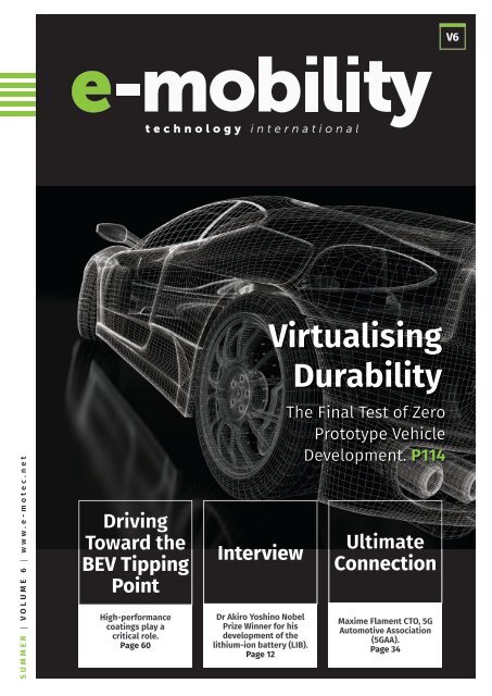
Virtualising<br />
Durability<br />
The Final Test of Zero<br />
Prototype Vehicle<br />
Development. P114<br />
Ultimate<br />
Connection<br />
Maxime Flament CTO, 5G<br />
Automotive Association<br />
(5GAA).<br />
Page 34
Editors Note<br />
Copper and aluminium<br />
wire splicing<br />
Multi-conductor cables<br />
Twisted wires<br />
Electric car sales topped 2.1 million globally last year, an increase of<br />
40% on 2018. As technological progress in the electrification of public<br />
transportation advances and the market for EV’s grows, electric vehicle<br />
usage is expanding significantly. Ambitious policy announcements have<br />
been critical in stimulating the electric-vehicle rollout in major vehicle<br />
markets in recent years. In 2019, indications of a continuing shift from<br />
direct subsidies to policy approaches that rely more on regulatory and<br />
other structural measures – including zero-emission vehicles mandates<br />
and fuel economy standards – have set clear, long-term signals for<br />
the auto industry and consumers that support the transition in an<br />
economically sustainable manner.<br />
The auto industry is responding with makers like VW who recently rolled<br />
off their last ICE vehicle to concentrate solely on electrically powered<br />
vehicles.<br />
ULTRASONIC METAL WELDING<br />
Supports e-Mobility and lightweight construction<br />
Aluminium and copper<br />
wire on 3D terminal<br />
Battery foil and tab welding<br />
Published by<br />
CMCorporation ltd<br />
234 Whitechapel Road<br />
London E11BJ UK<br />
info@cmcorp.co.uk<br />
www.e-motec.net<br />
Editor<br />
Mark Philips<br />
Associate Publishers<br />
Rachael McGahern<br />
Ujjol Rahman<br />
Marion Fairweather<br />
Anthony Stewart<br />
(ISSN) ISSN 2634-1654<br />
Copyright<br />
All rights reserved<br />
With the advent of 5G the market for Driverless cars connected to 5G will<br />
be constantly and instantly connected to traffic signals, and be capable<br />
of monitoring the roads through "vehicle-to-vehicle" communication,<br />
that lets them share data.<br />
The increased network speed will mean less delay in information<br />
transmissions and faster vehicle response times, and could eventually<br />
make autonomous vehicles safer on the road than human-driven<br />
vehicles.<br />
The technology is also being utilised by auto-makers in the<br />
manufacturing process as announced by Ford recently where they are<br />
building their own private 5G network to speed up manufacturing at its<br />
battery production plant in the UK.<br />
The advance of Electrified transport has led to countless new innovative<br />
solutions to address the challenges thrown up along the way, and within<br />
the contents of these pages we have presented just a few.<br />
This is an exciting time for the auto industry as they realise that<br />
they have the technology to bring a really cool driving experience to<br />
their customers while at the same time contribute to a much-needed<br />
reduction of CO2 emissions.<br />
Mark Philips - Editor<br />
High current /-voltage cable on terminal<br />
www.telsonic.com<br />
THE POWERHOUSE OF ULTRASONICS
03 | AVERE - Electro<strong>mobility</strong> Has<br />
Withstood the Coronavirus Crisis<br />
By Philippe Vangeel, Secretary General.<br />
Page 14<br />
Materials Research<br />
11| Pure Steel, Curing And Bonding Of Electric<br />
Motors’ Magnetic Steel Cores<br />
Contents<br />
Dr Christoph Lomoschitz, Axalta’s Global Product<br />
Manager for its Energy Solutions business and Filippo<br />
Veglia, Chief Commercial Officer, Tau. Page 46<br />
24| A Key You Cannot Pick Up<br />
Batteries + Charging<br />
Infrastructure<br />
18| Safe, Modular And Customizable<br />
Battery Assemblies<br />
Welcome to the latest development in the<br />
battery assembly process, Dr. Jean-Francois de<br />
Palma Head of R&D and Innovation for Mersen.<br />
Page 82<br />
03 12<br />
PAGE 56 10<br />
Power Electronics<br />
14<br />
PAGE 64<br />
Lubricant technology plays a key role in unlocking<br />
performance for new electrified drivetrain hardware.<br />
Adam Banks, eMobility Market Manager at Afton<br />
Chemical. Page 108<br />
14| Driving Toward the BEV Tipping Point<br />
High-performance coatings play a critical role<br />
Dave Malobicky, General Manager, Mobility PPG.<br />
Page 60<br />
02| Beyond Infinity<br />
The Rise of the Artificial Intelligence Electric Vehicle.<br />
Attention is shifting towards the interior design of cars<br />
insights from Dr. Yoshino. Page 10<br />
01| Electric Mobility – The<br />
Infrastructure Perspective<br />
Presented by Richard Gould at INTIS with guest<br />
commentary from the University of Duisburg<br />
Essen and Connected Kerb. Page 04<br />
07| Electrical Safety in Electric<br />
Vehicles (EVs)<br />
Different applications have different grounding<br />
strategies. Page 30<br />
21| Ultrasonics And Electro<strong>mobility</strong> -<br />
A Powerful combination, efficient, powerful, reliable,<br />
connected and eco-friendly, Andreas Hutterli Product<br />
Manager at Telsonic AG. Page 96<br />
12| Reducing Capex and Opex in zero<br />
emission bus operations is as easy as CYB<br />
CYB a project to facilitate operational excellence in<br />
zero-emission public transport. Page 52<br />
17| V2X Early Benefits<br />
It all comes together now Robert Gee, Innovation<br />
Manager, V2X and Future Connectivity, at Continental.<br />
Page 76<br />
Interviews<br />
14| A Leap Into The Modern Automobile Age<br />
Interview with Tino Fuhrmann the head of the MEB<br />
project who describes here the concept and design<br />
of the Modular Electric Drive Matrix, or MEB, platform.<br />
Page 64<br />
02| The past present and future of the Li-on,<br />
inventor’s opinion.<br />
Interview with Dr. Akira Yoshino, Nobel Prize Winner in<br />
Chemistry in 2019, Asahi Kasei Honorary Fellow and a<br />
professor at Meijo University in Nagoya. Page 12<br />
10| What Can the E-Mobility Market<br />
Learn From the Smartphone<br />
Industry?<br />
Why e-<strong>mobility</strong> is moving towards a full<br />
DC charging ecosystem. Page 42<br />
19| Europe’s bus market charges<br />
towards sustainability<br />
E-<strong>mobility</strong> solutions are enabling European<br />
nations to address their growing need<br />
for transport without compromising<br />
the environment, Frank Muehlon,<br />
Head of ABB’s global business for EV<br />
Charging Infrastructure. Page 86<br />
04| ISO 26262 Challenges<br />
Certified BMS are sparse on the market Claus<br />
Friis Pedersen, R&D Director at Lithium Balance,<br />
breaks down the certification process. Page16<br />
26| Sintered Silver Interconnects For<br />
Traction Inverter Assembly<br />
Gyan Dutt, MacDermid Alpha discusses silver sintering as<br />
a key technology enabling the EV revolution. Page 118<br />
Telematics + Connectivity<br />
08| Vehicle connectivity, Ultimate Connection<br />
Maxime Flament CTO, 5G Automotive Association (5GAA).<br />
Page 34<br />
27| Virtual Driving<br />
Testing telematics services over cellular networks.<br />
Jonathan Borrill, Francois Ortolan – Anritsu Corporation.<br />
Page 122<br />
20| 5G Is Critical To Achieve The Potential Of<br />
Digital Roads<br />
Luke Ibbetson, Head of Research and Development,<br />
Vodafone Group and 5GAA Board member. Page 90<br />
Thermal Management<br />
09| Next-gen Thermal Management<br />
Ultra-low viscosity Gap Filler Liquids Wolfgang Höfer<br />
Market Manager KERAFOL GmbH. Page 38<br />
13| Journey to Thermal Effiency<br />
Silicone-Based Thermal Interface Materials for<br />
Electric Vehicles Peter Walter, Senior Market Manager<br />
E-Mobility at WACKER SILICONES. Page 54<br />
06| Thermal Management for Electric<br />
Vehicles and their Infrastructure<br />
With the electric vehicle’s characteristic need for<br />
performance and efficiency, it is worth considering<br />
a direct refrigerant cooling approach Jim Burnett<br />
Director-Aspen Systems Inc. Page 24<br />
Thermal Management Solutions for Electric and Hybrid<br />
Vehicles. The MEDINA concept. Page 20<br />
22| Roadside Charging at 500Amps,<br />
Max Göldi, Market Manager Automotive Industry at<br />
HUBER+SUHNER. explains the world’s first cooled<br />
charging cable system that allows continuous charging<br />
at 500 Amperes. Page 98<br />
Powertrains<br />
14| Electric drives of Tomorrow.<br />
Drivetrain Components will Evolve due to Vehicle<br />
Electrification Dr. Stephan Demmerer Head of<br />
Advanced Engineering ZF Friedrichshafen AG,<br />
Germany. Page 68<br />
23| The E-Mobility Offensive Of A Turnkey<br />
Supplier Mastering the challenges of the transition<br />
from combustion to electric drive technologies<br />
- insights from GROB-WERKE, an award-winning<br />
electro<strong>mobility</strong> supplier. Page 104<br />
25| Virtualising Durability<br />
The Final Test of Zero Prototype Vehicle<br />
Development David Briant, Project Engineer, Claytex.<br />
Page 114
Electrically<br />
Mobile<br />
01<br />
CHARGING<br />
INFRASTRUCTURE<br />
Electric Mobility – The Infrastructure<br />
Perspective<br />
A lot has been written on the possibilities<br />
that electric <strong>mobility</strong> offers. In particular,<br />
micro <strong>mobility</strong> has been in the news a lot<br />
lately, especially with the current pandemic.<br />
We are presented a vision where electric<br />
scooter and e-bike sharing will revolutionise<br />
public transportation, eliminate cars in urban<br />
spaces and create green and pleasant cities.<br />
However, the infrastructure perspective<br />
is often missing from this narrative, despite<br />
accessible, smart charging offering huge<br />
potential to make electric, shared <strong>mobility</strong><br />
more convenient, more environmentally<br />
friendly and more cost effective.<br />
Thinking differently<br />
With personal internal combustion engine cars,<br />
we are all used to thinking a certain way about<br />
<strong>mobility</strong>. We drive until the tank is empty, fill<br />
up, and carry on. Except on long trips or for<br />
frequent drivers, filling up happens maybe once<br />
a week. Electric <strong>mobility</strong> forces a change in<br />
thinking, as now the vehicle is filled up when not<br />
in use, so you start the ride with a “full tank”.<br />
Shared micro <strong>mobility</strong> requires a further<br />
change. Now the vehicle is used much more<br />
frequently, and charging is the necessary<br />
annoyance that allows the user to do what they<br />
actually want, namely to be mobile. The vehicle<br />
is usually charged fully then used until empty, at<br />
which point it stands useless until it is charged<br />
again. For public sharing, dedicated personnel<br />
are required to organise charging or swap<br />
batteries. In private sharing, the user is required<br />
to invest their time finding a suitable place to<br />
plug in. A lot of activity in the background is<br />
needed to give the user that effortless ride.<br />
However, we at INTIS envisage smart<br />
infrastructure replacing that activity in the<br />
background. This requires accessible charging<br />
infrastructure allowing automatic opportunity<br />
charging, coupled with good use of data and<br />
communications. In this scenario, neither<br />
the user nor the operator need greatly<br />
concern themselves with making sure the<br />
vehicle gets its energy because that is taken<br />
care of by the infrastructure solution.<br />
Smart Services Provide Solutions,<br />
Not Just <strong>Technology</strong> – Commentary By<br />
The University Of Duisburg-Essen<br />
One area where the potential of electro<strong>mobility</strong><br />
is becoming apparent is in intralogistics,<br />
although this potential is often inhibited by<br />
incorrect usage behaviour. Vehicles are plugged<br />
in to charge as often as possible to minimise<br />
down-time. This high charging frequency<br />
may be suitable for lithium-ion batteries, but<br />
it drastically reducing the lifetime of leadgel<br />
batteries which are still very common in<br />
industry. Even worse, fleets and equipment are<br />
not usually updated all at once, meaning a mix<br />
of battery types ends up being charged the<br />
same way by the same equipment. This leads<br />
to a high replacement rate with associated<br />
materials, time, and overhead costs.<br />
Smart Charging – A Real World Application<br />
The solution is smart charging in connection<br />
with a fleet management system, where the<br />
charging infrastructure identifies the vehicle and<br />
battery type, connects to the fleet management<br />
system and determines the optimal charging<br />
behaviour based on stored information and<br />
historic usage patterns. These usage patterns<br />
provide information about the expected duration<br />
and distance of the next drive, based on daily<br />
driving patterns, which allow the smart charging<br />
application to calculate whether the battery<br />
level is sufficient or the battery needs to be<br />
charged. The availability of good data to develop<br />
relevant information is crucial to the efficacy of<br />
smart charging.<br />
Smart, inductive charging system<br />
The project Smart Inductive Solutions, a spinoff<br />
of the university Duisburg-Essen in Germany, is<br />
developing a system to address this issue. A datadriven<br />
approach is used to focus on value propositions<br />
for the individual customer, with very promising<br />
results coming from first tests currently running under<br />
real-world conditions. The gathering, transmission,<br />
and evaluation of required data in combination with<br />
wireless charging are key components of the project.<br />
The system consists of several core sub-systems,<br />
principally the charging infrastructure, the application<br />
server and multiple client workstations, as displayed<br />
in figure 2. Besides providing energy, the charging<br />
infrastructure provides bidirectional communication<br />
between the vehicles and the back-end. When a<br />
vehicle is parked, the charging infrastructure identifies<br />
this vehicle and loads the applicable battery data<br />
from the application server. The application server<br />
keeps track of each charging process and determines<br />
e-<strong>mobility</strong> <strong>Technology</strong> International 4 5<br />
<strong>Summer</strong> <strong>2020</strong>
Zero Emission Challenge<br />
<br />
Vehicle<br />
<br />
Changing Infrastructure<br />
<br />
Application Server<br />
<br />
Workstation<br />
Higher operational uncertainty requires either<br />
more vehicles or smarter tools.<br />
Which would you choose?<br />
<br />
<br />
Local Application<br />
Battery<br />
Microcontroller<br />
Server<br />
<br />
<br />
Display<br />
Screen<br />
Deployment diagram of the smart charging application<br />
<br />
Webserver Server<br />
<br />
Database System<br />
<br />
Webbrowser<br />
Live Vehicle &<br />
Battery Data<br />
Sycada gives you online access to location,<br />
status, range, SoC and energy usage data for<br />
all your dispatched vehicles.<br />
whether and how a vehicle should be<br />
charged. Data about vehicle status, battery<br />
health, battery state of charge, etcetera, is<br />
accessible on the application server from<br />
any device with a network connection.<br />
The advantages of wireless charging<br />
Smart charging combined with wireless<br />
charging technology can make electric micro<br />
<strong>mobility</strong> and intralogistics applications<br />
more useable, more environmentally<br />
friendly and more cost effective.<br />
In order to illustrate the potential,<br />
a logistics use case from the field of<br />
intralogistics is drawn upon: Employees are<br />
under a certain amount of time pressure<br />
and electric scooters are used for faster<br />
movement in the warehouses. Charging<br />
time is very limited and to take account of<br />
these special circumstances, a good dataset<br />
on battery consumption and charging<br />
time is essential to control charging cycles<br />
correctly. Wireless smart charging allows<br />
the employees to just park the scooters<br />
and continue with their assignment. The<br />
charging system takes care of the rest,<br />
deciding based on historical values and<br />
the battery type whether and to what<br />
parameters charging need take place. The<br />
next time a vehicle is required, the user is<br />
guided to an appropriate vehicle, meaning<br />
that battery condition and vehicle wear<br />
and tear across the fleet are optimised.<br />
Altogether, uptime is maximised with the<br />
user always having the <strong>mobility</strong> they required,<br />
while the vehicle is maintained in the best<br />
possible condition. Costs for replacement<br />
parts can be minimised and maintenance<br />
can be carried out in a planned way, thanks<br />
to condition monitoring of the vehicles and<br />
charging infrastructure. This allows the full<br />
potential of electric <strong>mobility</strong> to be harnessed.<br />
Smart Inductive Solutions will complete an<br />
evaluation phase with two pilot customers<br />
this year, with services able to be purchased<br />
from the beginning of 2021. Other use cases<br />
for smart inductive charging include micro<br />
<strong>mobility</strong> in public areas and delivery drones.<br />
Ubiquitous access to infrastructure<br />
No one worries about finding a road to drive to<br />
work or an electrical connection for their fridge.<br />
The infrastructure in those cases is ubiquitous<br />
and accessible. In order for infrastructure to truly<br />
support and enable electric vehicles it needs<br />
to be smart, but it also needs to be available<br />
where the customer needs it and accessible. In<br />
most cases infrastructure is, in fact, available;<br />
electricity and communications lines run under<br />
most streets in urban and suburban areas, and<br />
even outside of urban areas, electricity and<br />
communications infrastructure is never far away.<br />
Accessibility is the challenge, namely getting<br />
the necessary interfaces in place between<br />
the readily available infrastructure and the<br />
new EV customers who are now appearing.<br />
Additionally, it is not this interface, or the<br />
charging infrastructure, which prove the main<br />
Mindful Driving<br />
takes you further...<br />
Our in-vehicle coaching helps you hone the<br />
optimum driving style for your electric vehicles,<br />
saving you energy and extending your<br />
miles per charge.<br />
Adaptive Planning<br />
We monitor your operations and ensure you are<br />
alerted to any potential disruptions to your<br />
routes or vehicle charge plan.<br />
Charge Point<br />
Management<br />
We ensure chargers work seamlessly with<br />
your operations, and can be serviced remotely.<br />
e-<strong>mobility</strong> <strong>Technology</strong> International 6<br />
MINDFUL DRIVING • TRANSITION TO ZERO-EMISSION • eCAR SHARING<br />
www.sycada.com
expense and administrative hassle, but rather<br />
the civil engineering, works and organisation.<br />
This can be greatly reduced if interfaces are built<br />
into the roads, housing, and industrial estates<br />
during construction or scheduled maintenance,<br />
rather than as an add on afterwards.<br />
Enabling future smart cities, today –<br />
commentary by Connected Kerb<br />
Connected Kerb is a British start-up that<br />
has taken an innovative and future-proofed<br />
approach to developing and delivering smart<br />
cities technology. The company provides electric<br />
vehicle charging infrastructure solutions<br />
that enable future communities through<br />
connectivity. Its system is a smart cities platform<br />
that integrates both power and data at the<br />
kerbside to support electric, connected, and<br />
autonomous vehicles, as well as the deployment<br />
of advanced IoT technologies. With a focus on<br />
inclusivity, Connected Kerb’s vision is to create<br />
sustainable, future-proofed, and connected<br />
environments for all those within our society.<br />
Founder and Director of Innovation, Stephen<br />
Richardson explains that what differentiates<br />
Connected Kerb from traditional charge point<br />
vendors is that its technology is a two-part<br />
solution of flexible below-ground (power<br />
and data) infrastructure and an advanced<br />
charging and smart cities hardware solution.<br />
This solution is comprised of a Power &<br />
Data Pack that is sunk beneath the pavement<br />
and housed in a Node Box, and the visible,<br />
above-ground charge point socket and sensors.<br />
The components of the subterranean Node<br />
Box provides access to both power and data<br />
at the kerbside, which in turn enables and<br />
manages not only smart EV charging, but<br />
also provides a neutral platform for an array<br />
of different smart cities technologies.<br />
Richardson highlights that the aim in<br />
deploying a unique system such as this, is to<br />
deliver both flexibility and longevity. It enables<br />
upgrading over time (the system is modular<br />
and able to integrate new technologies) while<br />
also delivering a far broader value proposition<br />
than purely EV charging (multiple infrastructure<br />
projects in one single infrastructure solution),<br />
therefore providing value to a much broader<br />
cross-section of users than solely EV drivers.<br />
Once the Connected Kerb Node Box is<br />
installed it becomes a neutral host for a<br />
range of technologies, such as 5G, connected and/<br />
or autonomous vehicles and <strong>mobility</strong> services. Its<br />
connectivity allows for more effective management<br />
of EV chargers in real time (key for load management)<br />
and supports the many ambitions of smart cities.<br />
With current challenges considered, governments are<br />
under immense fiscal pressure, as well as increasing<br />
accountability for environmental commitments.<br />
Connected Kerb’s unique solution offers an integration<br />
of flexible innovations that is both cost-effective<br />
and scalable, allowing city planners to prepare<br />
for the future, while delivering for the present.<br />
The future of EV infrastructure<br />
Available, accessible, smart, and automatic<br />
charging infrastructure offers huge<br />
potential to transform transportation.<br />
Node Box<br />
Having ubiquitous interfaces to power and<br />
communications allows charging infrastructure<br />
to be turned into a commodity. Sharing stations<br />
for electric scooters or bikes can be installed at<br />
low cost and moved as demand and usage patterns<br />
change. Batteries or renewable energy sources<br />
can be installed to help deal with grid weaknesses.<br />
EV charging stations can be installed and operated<br />
at a fraction of the cost previously associated<br />
with these technologies.<br />
Smart charging and fleet management allows<br />
electric vehicles to have a higher up-time while<br />
also reducing wear and tear. Battery state of<br />
charge can be maintained at optimum levels,<br />
avoiding complete discharge or charge cycles<br />
which stress battery technology, meaning<br />
batteries last longer. Historic usage patterns<br />
and even weather data can be utilised. For<br />
example, if there is a week of rain and cold<br />
weather ahead, it is likely that shared scooters<br />
will not be used, so the state of charge can be<br />
set to conservation levels. However, if a long<br />
weekend ahead promises perfect weather,<br />
the scooters can be charged up to full to<br />
prepare for the expected surge in demand.<br />
Inductive charging with its automatic handsfree<br />
process, no wear and tear and ability to<br />
be seamlessly integrated into the landscape<br />
provides the final piece to the puzzle.<br />
At INTIS, we envisage a future infrastructure<br />
which is seamless, invisible, and automatic. A<br />
customer picks up an electric scooter from a<br />
charging station integrated into the pavement.<br />
The vehicle assigned to them has the correct<br />
state of charge to complete their trip and<br />
INTIS easy charge 5 inductive station for Metz moover electric scooters<br />
was chosen because its battery has experienced<br />
a lower number of charging cycles than other<br />
available options. The customer makes their way to<br />
their destination; already, a charging slot has been<br />
reserved for the vehicle and another trip has been<br />
lined up after a planned 20 minutes of charging<br />
to top up the battery. The customer reaches their<br />
destination and parks the scooter at another charging<br />
station in front of the train station, at which point<br />
the opportunity charging process is immediately and<br />
automatically started. At no point has the customer<br />
or the operator had to think about the energy<br />
needed to travel; the whole process is effortless.<br />
Infrastructure like this not only enhances the<br />
experience for the user, it reduces costs for the<br />
operator as well, both by reducing maintenance<br />
and increasing the longevity of the vehicle. Looking<br />
to the future of electric vehicles, this kind of<br />
infrastructure also allows battery capacity to be<br />
reduced, further saving both money and resources.<br />
Throughout the history of technology, each<br />
progressive step has involved greater use of<br />
resources and energy. The results of this are<br />
clear to everyone. Electric vehicles powered by<br />
renewable energy generation and enabled by<br />
smart infrastructure have the potential to buck this<br />
trend, providing truly sustainable <strong>mobility</strong>. •<br />
e-<strong>mobility</strong> <strong>Technology</strong> International 8 9<br />
<strong>Summer</strong> <strong>2020</strong>
Artificial<br />
Intelligence<br />
Electric Vehicles<br />
BATTERIES<br />
02<br />
The ongoing evolution in the automotive industry will change our<br />
driving experience. The focus of attention is shifting towards the<br />
interior design of cars – many interior concepts have been presented in<br />
recent years. But what exactly does the customer expect?<br />
NEW Lithium generation Balance n-BMS<br />
NEW generation n-BMS for<br />
for ISO 26262<br />
high-voltage<br />
certified<br />
applications<br />
battery management<br />
LiBAL Custom<br />
Applicaon<br />
Soware Layer<br />
Applicaon<br />
Soware Layer<br />
Link and and Interface Layer<br />
Base Soware Layer<br />
Full applicaon-level soware<br />
provided by Lithium Balance<br />
or your own code<br />
Open API<br />
Contains all safety-crical<br />
funcons, ISO 26262 cerfied<br />
“From 2025, AIEVs will gradually<br />
replace privately owned cars”. This<br />
quote by Dr. Akira Yoshino, Asahi<br />
Kasei Honorary Fellow and one of<br />
the inventors of the lithium-ion<br />
battery underlines the direction<br />
the automotive society is heading.<br />
“AIEV” – this abbreviation stands for<br />
“Artificial Intelligence Electric Vehicle”<br />
and is Dr. Yoshino’s vision of future<br />
<strong>mobility</strong>. By sharing fully autonomous,<br />
intelligent electric vehicles operating<br />
at the highest efficiency, the traffic<br />
as we know it today will change<br />
profoundly: Traffic accidents and<br />
privately-owned cars will decrease<br />
drastically, CO2 emissions will vanish.<br />
The cars will be moving energy<br />
storage systems, with fully automated<br />
charging cycles while discharging<br />
energy into the grid when not being<br />
used. The requirements for electric<br />
batteries will change – with the battery<br />
lifetime becoming an increasingly<br />
important factor. At the same time<br />
a high energy density for longdistance<br />
cruises with the EV will not<br />
be as important as it is today. “Range<br />
anxiety” – today one major obstacle<br />
for the popularity of electric vehicles<br />
– will become an issue of the past.<br />
This picture painted here is more<br />
than just Dr. Yoshino’s vision - it is<br />
slowly coming to life. The ongoing<br />
CASE (Connected – Autonomous –<br />
Shared – Electric) megatrends are<br />
disrupting the automotive industry.<br />
Development cycles are accelerating,<br />
fuelled by tightening environmental<br />
regulations, but also by rapidly<br />
changing user’s demands. Because<br />
not only the vehicle itself, but also the<br />
driving experience is about to change.<br />
Due to the increasing autonomy of<br />
the car the users will have to focus<br />
less on the traffic – and will have<br />
more time to spend on work, in-car<br />
entertainment or just relaxation. As a<br />
result of this development, the focus<br />
of attention will shift to the automotive<br />
interior, rather than the exterior. But<br />
what is the car user expecting from<br />
the future automotive interior?<br />
The Interior Is To Become<br />
The New Exterior<br />
In October 2019, Asahi Kasei Europe<br />
conducted a survey together with<br />
Cologne-based market research<br />
e-<strong>mobility</strong> <strong>Technology</strong> International 10<br />
institute Skopos, interviewing a total<br />
of 1,200 car users in Germany, France,<br />
Italy and the United Kingdom regarding<br />
their preferences for the automotive<br />
interior of the future. When asked<br />
about the interior of shared cars, 73.5%<br />
of all respondents who already have<br />
used or who could imagine to use car<br />
sharing put a special emphasis on the<br />
cleanliness of the car, while 51.2% value<br />
premium surfaces, for example for<br />
seats or dashboards. Asked about cars<br />
in general, 73,4% of the respondents<br />
see antibacterial seats and surfaces as<br />
beneficial, with 60.7% being inclined<br />
to pay an extra price for those kinds<br />
of surfaces. A question about surfaces<br />
which look and feel particularly<br />
premium shows a similar result, with<br />
73.5% of the respondents seeing a<br />
personal benefit in having premium<br />
surfaces in the car, and 61.8% being<br />
inclined to invest. 80.2% see benefit<br />
in an acoustic system which filters the<br />
vehicle’s background noise (63.8%),<br />
78% in an acoustic system optimizing<br />
the input of voice commands (61.9%).<br />
In addition, 51.8% consider noiseabsorbing<br />
seat covers and surfaces as<br />
a value-add inside the car (64.9%).<br />
An ISO 26262 ASIL C certified high voltage BMS platform with a unique<br />
software structure that leaves ample room for flexibility and customization<br />
• ISO 26262 ASIL C certified off-the-shelf<br />
Layered software structure with hardware and Base Software layer<br />
containing all safety critical functions, making the entire system ISO<br />
26262 ASIL C compliant<br />
• Embed your own code via open API<br />
Flexible Application Software layer with default LiBAL software options<br />
or possibility to embed your code with your own proprietary application<br />
level functions and algorithms<br />
• Distributed system suited for your application<br />
Range of Management Control Unit (MCU) and Cell Monitoring Unit<br />
(CMU) boards available off-the-shelf to match most application needs<br />
• High accuracy, robust algorithms<br />
Advanced SOC, SOH, and SOP algorithms with coulomb counting and<br />
dynamic OCV, with SOC accuracy to within ±0,5%<br />
contact@lithiumbalance.com<br />
www.lithiumbalance.com<br />
ISO 26262 cerfied hardware
“From 2025, AIEVs will gradually<br />
replace privately owned cars”.<br />
Dr. Akira Yoshino<br />
The Voice Of The Customer<br />
Is Loud And Clear<br />
Needs and demands towards the<br />
future automotive interior are<br />
becoming increasingly complex<br />
and diversified. For the customer<br />
the interior will play a decisive role<br />
when choosing the next car. For the<br />
OEMs, this development means an<br />
increasing innovation pressure.<br />
Heiko Rother, general manager,<br />
business development, Automotive at<br />
Asahi Kasei Europe, on the increasing<br />
importance of the automotive interior:<br />
“Customer expectations are not<br />
changing over night, but gradually and<br />
much faster than we have seen in the<br />
past. More than half of the car buyers<br />
in Europe are ready to change their<br />
brand. A great chance for OEMs to<br />
win new customers by implementing<br />
convincing technologies which are<br />
touching all senses, addressing<br />
human emotions and needs.”<br />
As a highly diversified technology<br />
company covering a broad range of<br />
advanced materials and technologies<br />
from performance plastics and foams,<br />
stain- and odor repellent fibers for<br />
automotive interior, and electronic<br />
sound and sensing solutions, Asahi<br />
Kasei is offering solutions to these<br />
changing needs. By establishing<br />
its European Headquarter in<br />
Düsseldorf, Germany, in April 2016,<br />
the company is positioning itself as<br />
a partner for the European OEMs<br />
and Tier-1 suppliers to overcome<br />
the challenges Dr. Yoshino’s vision of<br />
future <strong>mobility</strong> is foreshadowing.<br />
The past present and future of the Li-on<br />
Interview with Dr. Akira Yoshino, Asahi Kasei Honorary Fellow and<br />
2019 Nobel Prize in Chemistry in recognition of his achievements in<br />
the research and development of the lithium-ion battery (LIB).<br />
e-motec: The arrival of Lithium<br />
Ion batteries have been nothing<br />
short of a blessing in the world<br />
of technology and gadgets. As a<br />
recent winner of the Nobel Prize<br />
in chemistry for the creation<br />
of the first commercially viable<br />
lithium-ion battery, can you explain<br />
your vision back in 1985 of where<br />
you imagined their best uses?<br />
Dr. Akira Yoshino: I started to<br />
work on the lithium-ion battery<br />
technology in the early 1980s,<br />
together with two colleagues.<br />
Back in those days the world<br />
was waiting for a new battery<br />
technology, replacing the primary<br />
batteries that were powering the<br />
portable electronic devices. When<br />
we were developing the secondary<br />
lithium-ion battery, we were mainly<br />
thinking about its application in<br />
Sony’s portable 8mm camera. At<br />
that time, we estimated a yearly<br />
production of around 12 million<br />
batteries worldwide – and nobody<br />
was thinking of its application<br />
in the automotive. The rising<br />
popularity of portable devices<br />
such as cell phones and notebooks<br />
beginning in the 1990s then<br />
changed the scenery completely.<br />
e-motec: Was there a Eureka<br />
moment/discovery that led you to<br />
lead the team that would build the<br />
lithium ion battery prototype?<br />
Dr. Akira Yoshino: This is a<br />
funny story and it shows how<br />
little coincidences can lead to<br />
something great. In 1982, we were<br />
already working on the battery,<br />
but still struggling with the right<br />
combination of anode and cathode<br />
materials. During spring time I<br />
was cleaning up my lab when I<br />
stumbled across a research paper<br />
by John Goodenough, something<br />
I was planning to read for a while<br />
but just could not find the time to<br />
do so. Now I had the time! In this<br />
paper Goodenough elaborated<br />
on lithium cobalt oxide as a<br />
suitable cathode material. And<br />
this was the Eureka moment. We<br />
reconfigured our battery, using<br />
a carbon-based material for the<br />
anode, and lithium cobalt oxide<br />
for the cathode – and it worked!<br />
e-motec: The impact of Li ion<br />
batteries has pushed electric<br />
vehicles from mere concept to a<br />
reality. With the appetite for energy<br />
storage solutions whetted along<br />
with the transport infrastructure<br />
electrification, there will be<br />
several contenders challenging<br />
the throne currently occupied<br />
by Li-ion. Where do you see the<br />
developments in this sector<br />
taking the Li-Ion in the future?<br />
Dr. Akira Yoshino: The lithium-ion<br />
battery is a mature technology – but<br />
only in its application in portable<br />
electronic devices. When it comes<br />
to its application in the automotive,<br />
there is still a lot of room for<br />
improvement. I personally am very<br />
much interested in reviewing the<br />
fundamentals of lithium-ions. The<br />
movements of lithium-ions differ<br />
greatly – depending on using a<br />
liquid or a solid electrolyte.<br />
By completely understanding<br />
the behavior of lithium-ions,<br />
we may be able to increase<br />
their speed. This will greatly<br />
enhance the current lithium-ion<br />
battery technology. Then, there<br />
is the use of different materials.<br />
Next to the electrolyte, using<br />
new material combinations for<br />
the positive electrode (nickel,<br />
cobalt and manganese) and the<br />
negative electrode (graphite and<br />
silicone) still bears potential.<br />
Dr. Akira Yoshino inventor of lithium-ion battery.<br />
Looking to the next-generation<br />
battery technology, the solid-state<br />
battery is a promising candidate.<br />
Japanese companies like TDK,<br />
Kyocera and Murata Manufacturing<br />
are starting to commercialize<br />
small solid-state batteries, for<br />
examples for applications in<br />
sensors. But it will take time before<br />
this battery technology finds its<br />
way into the automotive –<br />
maybe more than ten years.<br />
Asahi Kasei is also conducting<br />
research in this field. •<br />
e-<strong>mobility</strong> <strong>Technology</strong> International 12 13<br />
<strong>Summer</strong> <strong>2020</strong>
ELECTRIFICATION PLANNING<br />
03<br />
Electro<strong>mobility</strong> Has<br />
Withstood the<br />
Coronavirus Crisis<br />
Let’s Make It the Mass Zero-Emission Means of Transportation<br />
The global pandemic caused by the COVID-19 crisis is at<br />
the root of a major shock for the world’s economy. The<br />
automotive sector was no exception, with an expected<br />
decline of 21% in the production of light vehicles<br />
globally, equivalent to more than 15 million fewer cars<br />
being put on the market (Source: Frost&Sullivan, <strong>2020</strong>).<br />
Fortunately, the EV sector was able to withstand<br />
the worst impacts of the crisis and is in the midst<br />
of recovering comparably quicker which will<br />
of course have substantial and much needed<br />
benefits to decarbonise the transport sector.<br />
The Strength of Electro<strong>mobility</strong><br />
Makes for a Faster Recovery<br />
During the crisis, the productions and sales of coming<br />
to the market. However, following the summer, a<br />
steady growth in the sales of electric vehicles is<br />
expected – this is due to some key advantages that this<br />
technology provides. (Source: Frost&Sullivan, <strong>2020</strong>)<br />
Some of these which are quite clear and well<br />
known: EVs are sustainable as they have zero<br />
emissions, require very little maintenance, as well<br />
as are becoming increasingly cost-effective.<br />
Furthermore its unique position as a new<br />
technology on the cusp of mass uptake by<br />
consumers drives specific business advantages<br />
that can contribute to this growth.<br />
Manufacturers are also likely to collaborate more<br />
to produce cutting edge-technologies. The production<br />
of batteries will become a more relevant part of the<br />
value-chain. The broader ecosystem is also on the<br />
path to become more integrated and innovative.<br />
The Opportunity for a Green Recovery!<br />
Europe must take this opportunity to invest<br />
further in green and zero emission technologies.<br />
It would be extremely dangerous to postpone<br />
our overarching decarbonisation commitments<br />
until the economy is back on track. •<br />
By Philippe Vangeel, Secretary General<br />
e-<strong>mobility</strong> <strong>Technology</strong> International 14 15<br />
<strong>Summer</strong> <strong>2020</strong>
BATTERIES<br />
04<br />
ISO 26262<br />
Challenges<br />
While the demand is present, the certification process is<br />
neither simple nor cheap, and solutions for off-the-shelf<br />
certified BMS are sparse on the market.<br />
Claus Friis Pedersen, R&D Director at Lithium Balance.<br />
ISO 26262 challenges for BMS<br />
The ISO 26262 functional safety standard<br />
is becoming an absolute necessity for<br />
electric passenger cars, road vehicles, and<br />
other EVs on the market. Considering that<br />
the Battery Management System (BMS) is<br />
a defining factor for the safety of these<br />
electric applications, certification on at<br />
least ASIL C level is also becoming a market<br />
need for BMS. While the demand is present,<br />
the certification process is neither simple<br />
nor cheap, and solutions for off-the-shelf<br />
certified BMS are sparse on the market.<br />
The main reason for this is probably the<br />
fact that the ISO26262 demands that you<br />
provide a calculated estimate of the rate of<br />
hazard occurrence due to random hardware<br />
failures. Furthermore, you are obliged to<br />
prove that the so-called Probabilistic Metric<br />
for Hardware Failure (PMHF) is achieved.<br />
To support this, over a hundred different<br />
documents and reports are required to<br />
be submitted to an accredited, external<br />
organisation for analysis, review, and<br />
approval for obtaining an ISO 26262<br />
certification for a specific BMS product.<br />
Although the standard offers some options<br />
for configuration and calibration, such a<br />
certified product typically lack flexibility too,<br />
as recertification is subject to even minor<br />
safety critical modifications. Therefore, a<br />
fully ISO 26262 certified BMS is most often<br />
purchased as a customised product for a<br />
single or limited amount of product lines.<br />
Breaking Down The Certification<br />
And Development Process<br />
“Lithium Balance has been through the ISO<br />
26262 certification procedure on multiple<br />
occasions, first, during the development<br />
of a customised BMS created for some of<br />
the major electric passenger car OEMs.<br />
Afterwards, challenging the market norms,<br />
we found a working solution for the<br />
development of an ISO 26262 certified BMS,<br />
that comes off-the-shelf, and maintains its<br />
flexibility regardless of the strict certification<br />
process, the third generation n-BMS<br />
platform, thanks to a clever software-level<br />
design.” - Claimed Claus Friis Pedersen,<br />
R&D Director at Lithium Balance.<br />
Whereas the development of an ISO 26262<br />
certified BMS solution took us over two years,<br />
with the n-BMS platform, the (re-)certification<br />
process for custom specific solutions<br />
can be cut down to a fraction hereof.<br />
ISO 26262 defines requirements for the<br />
whole life cycle of a product, including<br />
management, development, production,<br />
operation, service, and decommissioning,<br />
and requires that the fulfilment of all<br />
requirements are proven, documented,<br />
reviewed, and verified/validated, while<br />
potential failures are analysed, and risks<br />
specified and quantified, Claus explained<br />
For the n-BMS platform, the process started<br />
with breaking down the development and<br />
certification procedure into three phases,<br />
the concept phase, product development phase, and<br />
post-RFP phase. These phases were then broken down<br />
to smaller stages as well. The concept phase was<br />
consisting of an item definition stage, where the overall<br />
functions and basic design of the BMS was defined,<br />
a stage where Hazard Analysis and Risk Assessment<br />
(HARA) was made, an important analysis technique to<br />
ensure potential safety hazards are considered, and<br />
then the definition of the functional safety concept<br />
stage, where the main safety goal was set. For the<br />
n-BMS, “Avoiding battery SOA (Safe Operating Area)<br />
violation” was defined, as well as further safety<br />
functions and steps, such as what safety support<br />
functions shall be applied, when the BMS should<br />
provide warnings, and when should it enter “Safestate”,<br />
where all battery contactors are disconnected.<br />
The product development phase included the<br />
actual development of the hardware and software by<br />
first looking at the BMS on a system level, deriving<br />
What truly makes<br />
the n-BMS platform<br />
unique, however,<br />
is its software-level<br />
design.<br />
e-<strong>mobility</strong> <strong>Technology</strong> International 16 17<br />
<strong>Summer</strong> <strong>2020</strong>
n-BMS Platform MCU.<br />
code in the BMS, without<br />
any risk posed on the ISO 26262<br />
certification, thanks to a clever design.<br />
The n-BMS platform’s software has been<br />
separated into two layers, the Base-Layer-<br />
Software (BSW) and the Application-Layer-<br />
Software (ASW). All safety critical functions<br />
and hardware drivers are included in the BSW,<br />
allowing more flexibility and customisability<br />
for the ASW, which contains non-safety critical<br />
features only, such as SoX algorithms. The two<br />
layers are separated by an open API interface<br />
layer, making the connection between BSW<br />
and ASW seamless and programming simple.<br />
the safety requirements set from the<br />
functional safety concept, creating a system<br />
architecture, defining safety mechanics for<br />
detection and avoidance of failures, and<br />
safety analyses at a system level, such as<br />
Failure Mode and Effect Analysis (FMEA) and<br />
Failure Tree Analysis (FTA). For an ASIL-C<br />
certification there shall be no potential<br />
single-point failures in the system that<br />
are not covered by a safety mechanism.<br />
Development on a hardware level was<br />
made in a similar structure. After deriving<br />
Hardware Safety requirements and test<br />
specifications, a detailed hardware design<br />
was made with HW/SW interface specification<br />
and test specification, which included a 32<br />
bit RISC floating-point and dual core lockstep<br />
CPU on the master board and several slave<br />
boards to suit a number of different customer<br />
interests in terms of number of battery cells<br />
per slave and connector types. At this level<br />
quantitative analysis, FMEDA and quantitative<br />
FTA were conducted to provide the previous<br />
figures for the likelihood of failure.<br />
Risk-Free Implementation Of<br />
Your Own Software Code<br />
What truly makes the n-BMS platform<br />
unique, however, is its software-level<br />
design. It includes an open API that allows<br />
customers to include their own software<br />
e-<strong>mobility</strong> <strong>Technology</strong> International 18<br />
In addition, a complete ASW package of<br />
functionality has also been developed for<br />
the n-BMS platform, with full configurability,<br />
so the depth of customisation is completely<br />
up to the user. Via the open API, users can<br />
safely supplement, or completely replace<br />
the added ASW functionality with their own<br />
custom algorithms and battery models using<br />
the MATLAB toolbox or Simulink codes, without<br />
any effect on the ISO 26262 certified.<br />
The software design was followed by proving<br />
freedom from interference between safety<br />
critical parts and non-safety critical parts,<br />
and further tests, including environmental<br />
tests, EMC test, system integration test,<br />
and Fault Injection test to invoke safety<br />
mechanisms. With that, the product was ready<br />
for production, however, further paperwork<br />
to the independent organisation, TÜV SÜD in<br />
Lithium Balance’s case, was still filed during<br />
the production, service, and decommissioning.<br />
Conclusion<br />
With the third generation n-BMS platform, we<br />
developed one of the first ISO 26262 certified<br />
BMS off-the-shelf, with a “sandbox” ASW that<br />
allows for a large degree of customisability<br />
without any negative effects on its safety<br />
functions, pioneering the way towards safer<br />
electric vehicles on the road and shorter<br />
time-to-market for automotive OEMs, who will<br />
not have to go through the lengthy and rather<br />
costly ISO 26262 certification process. •<br />
Hugo Benzing GmbH & Co. KG<br />
Daimlerstrasse 49 - 53<br />
70825 Korntal - Münchingen<br />
Germany<br />
E-Mail: info@hugobenzing.de<br />
Phone: + 49 711 8000 6 - 0
THERMAL<br />
MANAGEMENT<br />
05<br />
A Step<br />
Toward<br />
E-Mobility<br />
Thermal Management<br />
Solutions for Electric<br />
and Hybrid Vehicles.<br />
The MEDINA concept<br />
The protection of the environment<br />
is increasingly becoming a priority<br />
on the political agenda around the<br />
globe. The UN-Paris agreement sets<br />
a target of 1.5°C on global warming,<br />
Green parties are gaining influence<br />
and even running or participating in<br />
various governments (e.g. Austria)<br />
and the youth movement ‘Fridays<br />
for future’ is attracting more and<br />
more attention and support.<br />
The transportation sector with<br />
combustion engines is one of the<br />
major sources of CO2 emissions.<br />
Automotive and machinery<br />
equipment manufacturers all<br />
over the globe are searching for<br />
alternative drive solutions, most<br />
importantly Battery Electric Vehicles<br />
(BEV) and Fuel Cell Electric Vehicles<br />
(FCEV) or hybrid systems with both a<br />
combustion engine and electrical.<br />
To ensure safety and to increase<br />
longevity of electric vehicles, the<br />
Drivetrain and energy systems must<br />
Schematic overview of heat exchangers used in hybrid vehicles<br />
operate under optimal thermal<br />
conditions. At the same time,<br />
applications demand increased<br />
power, capacity, or charging/<br />
discharging rates (C-rates). As<br />
temperature boundaries are<br />
significantly more restricted<br />
compared to internal combustion<br />
engines (ICE’s), observing these<br />
limits is both more important<br />
and more difficult. Electrical<br />
motors overheating will lead to an<br />
exponential decrease in lifetime.<br />
Lithium-ion-batteries should<br />
operate within a temperature range<br />
of 20 to 45°C. If they overheat, the<br />
electrochemical aging process<br />
starts. If they are functioning<br />
at temperatures below 20°C,<br />
performance decreases significantly.<br />
In addition, converters, transformers<br />
and the power electronics all face<br />
deterioration due to overheating.<br />
So, generally speaking, for the<br />
lifetime and performance an<br />
efficient and consequent thermal<br />
management is mandatory.<br />
To face these challenges, AKG<br />
Group - a company founded in<br />
1919 in Hofgeismar, Germany<br />
that has grown from a small<br />
production facility into a worldwide<br />
manufacturer of specialised cooling<br />
systems - has collaborated with<br />
Aurora, a leading global supplier<br />
of HVAC solutions for low volume<br />
and off-road applications and<br />
high-end applications, founded<br />
in 1930 also in Germany.<br />
Together, they have developed<br />
a range of products solving these<br />
problems and allowing each<br />
component to run in optimized<br />
thermal conditions, extending life<br />
and increasing effectiveness.<br />
Special cold plates, designed<br />
according to heat rejection maps<br />
and completely new architectures<br />
for battery cooling, offer one<br />
type of solution. Developed in<br />
cooperation with leading research<br />
institutes and universities (e.g.<br />
FEV and Aachen University), these<br />
advancements warrant consideration.<br />
e-<strong>mobility</strong> <strong>Technology</strong> International 20<br />
21<br />
<strong>Summer</strong> <strong>2020</strong>
diagonal, U-flow, multi passages) are<br />
also completely selectable. Aurora’s<br />
long experience in refrigerant cycle,<br />
HVAC and all required components<br />
ensures the systems’ optimal<br />
operation in all conditions.<br />
To offer flexible solutions to<br />
all kinds of customers, it is possible<br />
to integrate MEDINA not only as a<br />
complete system in a vehicle but<br />
also to have a step-by-step<br />
integration. An OEM may start with<br />
a battery thermal management<br />
system (BTMS) only or with<br />
the hydraulic system as single<br />
heat source for the pump and<br />
later, in stage two, integrate<br />
additional components.<br />
Openness, flexibility,<br />
and high value in technical<br />
support and product<br />
performance are key for<br />
AKG-Aurora in serving their<br />
customers; this is the driving<br />
force of the MEDINA concept.<br />
With their MEDINA concept,<br />
AKG and Aurora offer<br />
the market an option for<br />
substantial overall reduction<br />
in energy consumption for<br />
electric vehicles and this<br />
a potential for global CO2<br />
emission reduction. •<br />
“An option for<br />
substantial<br />
overall reduction<br />
in energy<br />
consumption for<br />
electric vehicles<br />
and with this<br />
a potential for<br />
global CO2<br />
emission reduction.”<br />
A<br />
C<br />
The MEDINA concept allows<br />
two ways of optimization: either<br />
offering the same size of battery<br />
with significantly more autonomy<br />
(if heating or cooling is needed),<br />
or maintaining the same vehicle<br />
range or operating time with a<br />
reduction in the size and cost of the<br />
battery (depending on utilization<br />
and conditions up to 40 %).<br />
AKG and Aurora jointly have<br />
developed a software to calculate<br />
the possible benefits under<br />
specific conditions and with this<br />
can support their customers<br />
already in the development<br />
phase with optimization.<br />
The core element, the heat pump,<br />
is again a joint development. AKG’s<br />
high performance SSC (Stacked Shell<br />
Cooler) contributes significantly<br />
to the performance of the heat<br />
pump. Due to their extraordinary<br />
flexibility in design, each heat<br />
exchanger is developed for the<br />
physical properties of the media and<br />
working conditions. Connections and<br />
flow directions (parallel, counter,<br />
(Above) Homogeneous temperature<br />
distribution on a cold plate 3D-model<br />
(left) and prototype (right) of a liquid<br />
cooled battery module<br />
B<br />
D<br />
E<br />
“Openness, flexibility, and high value in technical<br />
support and product performance are key”<br />
(A) Schematic representation of the<br />
MEDINA concept . (B) Energy demand<br />
comparison of AC-system with PTC<br />
heating vs. MEDINA over a year.<br />
(C) A 3D-Model of the heat pump system<br />
and (D) Heat sink for power electronics.<br />
(E) Stacked Shell Cooler.<br />
e-<strong>mobility</strong> <strong>Technology</strong> International 22 23<br />
<strong>Summer</strong> <strong>2020</strong>
THERMAL MANAGEMENT 06<br />
The growth of Electric Vehicles (EV)<br />
ushers in a need for novel thermal<br />
management solutions. Heat loads<br />
driven by ever increasing and<br />
higher energy densities in battery<br />
technology, electronics, and rapid<br />
charging require high efficiency cooling<br />
systems in compact packages. Also,<br />
the battery performance in terms<br />
of total energy stored and power<br />
output significantly decreases as the<br />
temperature becomes too low. The<br />
thermal issues are exacerbated by<br />
the necessity to keep batteries within<br />
tight thermal boundaries in order to<br />
maintain performance and reliability<br />
for extended use. Engineers are more<br />
and more reliant on active cooling to<br />
meet these requirements. We’ll look<br />
briefly at the issue of heating and<br />
cooling batteries using a secondary<br />
liquid loop and a direct refrigerant<br />
approach and explore the trade-offs<br />
between these two approaches.<br />
Thermal<br />
Management<br />
For Electric<br />
Vehicles<br />
and Their<br />
Infrastructure<br />
Batteries can operate over a<br />
reasonable range of temperatures, but<br />
function best, last longest, and hold<br />
their charge longest when maintained<br />
in a temperature range of ~20°C to<br />
~40°C. A typical ambient temperature<br />
range for electric vehicles would have<br />
a reasonable maximum of ~60°C and a<br />
minimum of ~-30°C. This means that<br />
active cooling and heating is a necessary<br />
part of the Battery/E-vehicle system.<br />
Furthermore, charging and particularly<br />
rapid charging further confines the<br />
temperature range. Extreme cold and<br />
high heat reduce charge acceptance,<br />
so the battery must be brought to a<br />
moderate temperature before charging.<br />
The most widespread active<br />
cooling methods used in industry are<br />
thermoelectric and vapor compression<br />
refrigeration (VCR). Other options<br />
for active cooling include magnetic,<br />
thermo-acoustic and thermo tunneling.<br />
In 2010, a DOE government-sponsored<br />
study compared vapor compression<br />
(VC) with five competing technologies,<br />
Jim Burnett Director-Aspen Systems Inc.<br />
including thermo-acoustic,<br />
thermoelectric and magnetic<br />
methods. The results determined<br />
that VC systems are at least<br />
three times more efficient than<br />
all other current options—and<br />
since 2010, much progress has been<br />
made in efficiency of VCR, making<br />
it, by far and away, the best cooling<br />
option available. Vapor compression<br />
is more efficient and lighter than<br />
alternative technologies in most<br />
applications. Simplest heating method<br />
used in battery powered vehicles is<br />
resistance heating, however, vapor<br />
compression-based heating (VCH)<br />
which uses significantly lower battery<br />
power is a desirable alternative.<br />
Figure 1 Miniature Compressor.<br />
e-<strong>mobility</strong> <strong>Technology</strong> International 24
Direct Refrigerant Vapor Compression Cycle.<br />
Direct Refrigerant Thermal Management for Battery Operated<br />
Vehicles and Charging Stations<br />
Air T °C COP DX °C<br />
10 8.0<br />
20 6.1<br />
30 4.5<br />
40 3.2<br />
50 2.3<br />
60 1.5<br />
Table 1 Direct Refrigerant Cooling COP<br />
Ambient T °C<br />
COP<br />
-30 Heater Required<br />
-20 Heater Required<br />
-10 0.7<br />
0 1.4<br />
10 2.3<br />
20 3.4<br />
Table 2 Direct Refrigerant Heating COP<br />
Vapor Compression with Secondary Coolant Loop<br />
Air T °C<br />
COP LIQ<br />
Ambient T °C<br />
COP<br />
10 6.6<br />
-30 Heater Required<br />
20 5.0<br />
-20 Heater Required<br />
30 3.6<br />
-10 0.6<br />
40 2.5<br />
0 1.1<br />
50 1.7<br />
10 1.8<br />
60 1.2<br />
20 2.7<br />
Table 3 Liquid Loop Cooling COP<br />
Table 4 Liquid Loop Heating COP<br />
Vapor Compression Based Refrigeration & Heating<br />
Simply stated, vapor compression refrigeration<br />
(VCR) systems move heat from a cold source<br />
to a heat sink based on the physics of phase<br />
change heat transfer. The basic components<br />
of this system include compressor (the heart<br />
of the system), condenser, expansion valve,<br />
and evaporator. The compressor receives<br />
low temperature/pressure refrigerant vapor<br />
and compresses it as high density and high<br />
temperature vapor into the condenser, where<br />
heat is removed to the environment causing the<br />
refrigerant to condense to hot liquid. The high<br />
temp liquid exits the condenser and moves into<br />
the expansion valve. Here the liquid sustains<br />
a pressure drop that lowers the temperature<br />
of the refrigerant at the exit of the expansion<br />
valve. The result is a low temperature two-phase<br />
mixture that enters the evaporator, and as it is<br />
exposed to the heat source, the heat boils off the<br />
liquid refrigerant through evaporation absorbing<br />
heat from the source. The low temperature,<br />
low pressure gas then re-enters the compressor<br />
completing the process. In the heating mode<br />
of a compression cycle, through the use of a<br />
four-way valve, the former evaporator becomes<br />
the condenser, heating the cold battery and<br />
the former condenser becomes the evaporator<br />
absorbing heat from the environment.<br />
Rotary Compressor<br />
The most prevalently used refrigeration<br />
compressors for general applications have<br />
been reciprocating compressors. In automotive<br />
applications, shaft driven swash plate compressor<br />
has been the compressor of choice. In a<br />
battery-operated vehicle, a new highly efficient,<br />
compact and lightweight alternative to the<br />
previous standards are now available.<br />
A line of miniature and small (1.4cc to 7.6cc<br />
displacement), variable speed (2000 to 6500<br />
RPM) BLDC rotary refrigeration compressors<br />
were successfully developed in the US, precision<br />
manufactured, individually performance tested,<br />
and sold worldwide for wide ranging applications.<br />
These compact and lightweight BLDC rotary<br />
compressors have inherently high reliability in<br />
mobile applications. This has been demonstrated<br />
by the US Military’s use of these systems over<br />
ten years of extreme field use. Over 4000<br />
Environmental Control Units (ECU’s) using the<br />
smallest of these compressors have been fielded<br />
by the Military to cool communication electronics<br />
on board Mine Resistant Ambush Protected<br />
(MRAP) vehicles. These small rotary compressors<br />
are more efficient (up to twice as efficient as<br />
reciprocating BLDC compressors) and compact<br />
compared to reciprocating compressors (one<br />
tenth of the size and weight of reciprocating BLDC<br />
compressors). These efficient, reliable, compact<br />
and lightweight BLDC variable speed compressors<br />
are already being effectively used in various<br />
applications, including electric vehicle charging<br />
stations, transportable military communications<br />
electronics, industrial lasers, and medical devices.<br />
These miniature compressors have overcome<br />
previous obstacles to using vapor compression<br />
cooling systems in extreme operating conditions<br />
and applications, which demand high-reliability<br />
in mobile operation, very low weight, and<br />
small available space. Shown in Figure 1, is a<br />
compressor that was specifically engineered<br />
to make possible the miniaturization of vapor<br />
compression cooling systems for military<br />
electronics and laser cooling. The extremely high<br />
capacity and high efficiency in such a small and<br />
lightweight compressor along with its undisputable<br />
reliability in mobile applications are the key<br />
enabling factors in miniature refrigeration and<br />
heating systems and offer excellent potential<br />
for on-board battery cooling in vehicles.<br />
This analysis will compare the cooling<br />
and heating efficiency of a battery thermal<br />
management system using vapor compression<br />
technology with and without a secondary<br />
pumped coolant loop. As shown in the direct refrigerant<br />
solution Figure 2, the refrigerant is run directly through<br />
the battery cold plates, which are the evaporator in<br />
this system. The battery cold plate is designed as<br />
an evaporator with special care taken to assure the<br />
two-phase flow is uniformly distributed and that the<br />
refrigerant pressure is safely contained. The batteries<br />
are mounted directly to the cold plate, minimizing<br />
conduction losses, and maximizing the efficiency of<br />
the system. In addition, the refrigerant provides phase<br />
change heat transfer in the cold plate, assuring that<br />
the temperature across the battery bank is uniform.<br />
The efficiency of vapor compression systems is<br />
typically presented as the coefficient of performance or<br />
COP of the system. The COP is the ratio of the cooling<br />
provided and the power drawn by the system. Table 1<br />
shows a calculation of the COP for a direct refrigerant<br />
cooled system with varying ambient temperature and<br />
a constant battery cold plate temperature of 20C. This<br />
is a simple analysis designed to show correlations<br />
between temperature and COP using R134a (similar in<br />
performance to R1234yf approved for vehicle use) as<br />
the refrigerant. Fan power has not been included. As<br />
an example, at an air temperature of 40°C, a direct<br />
refrigerant cooled system would provide 3.2 watts of<br />
cooling for every watt of power draw. Alternatively,<br />
if 3200 watts of cooling were required the system<br />
would draw 1 KW of power under these conditions. As<br />
e-<strong>mobility</strong> <strong>Technology</strong> International 26 27<br />
<strong>Summer</strong> <strong>2020</strong>
indicated in the table, there is a strong correlation<br />
between ambient temperature and COP.<br />
This system will also need to function at air<br />
temperatures significantly below 10°C. By employing<br />
a four-way valve, the system can be reversed and<br />
turned into a heat pump. By reversing the refrigerant<br />
flow, the heat is drawn from the cold ambient air,<br />
and heating is supplied to the battery cold plate.<br />
As a heat pump, the same COP calculation can be<br />
used to assess the efficiency and power draw as a<br />
function of ambient temperature. In this case, the<br />
battery “hot plate” temperature is now set at 40C to<br />
provide heating. The COP performance under these<br />
conditions is shown in Table 2. As can be seen in the<br />
table, at very low temperatures, up to an ambient of<br />
approximately -10C, a heater is more efficient than<br />
the vapor compression system at maintaining the<br />
required plate temperature and would be required<br />
under these operating conditions. For the heating<br />
cycle, the COP has the same meaning as for the<br />
cooling cycle. At 0C the system will provide 1.4<br />
watts of heating for every watt of power drawn.<br />
Vapor Compression with Secondary Coolant Loop<br />
In this scenario, the vapor compression system<br />
heats and cools the pumped coolant and the<br />
evaporator is collocated with the condenser,<br />
compressor, and expansion valve in a compact<br />
assembly, similar to that shown in Figure 4. The<br />
battery cold plate does not need to be designed<br />
as an evaporator that carries the refrigerant<br />
pressures. Table 3 shows the COP of the coolant<br />
loop design in cooling mode and Table 4 shows<br />
the COP of the coolant loop design when used<br />
as a heat pump for heating the coolant loop. As<br />
shown in Table 4, a heater is required at low<br />
temperature. This is because the r134a refrigerant<br />
used for this analysis is a vacuum at these low<br />
temperatures and there is no refrigerant flow.<br />
Direct Refrigerant & Liquid Loop<br />
Cooling Conclusions<br />
The direct refrigerant approach is more efficient<br />
for both the heating and cooling cycles. See the<br />
graph in Figure 5, which plots the power saved per<br />
kilowatt for the cooling and heating cycle for the<br />
direct refrigerant and secondary coolant approaches.<br />
With direct refrigerant, the only active component<br />
is the compressor, which drives the refrigerant<br />
through the battery heat transfer plate, providing<br />
phase change heat transfer at a uniform temperature<br />
for the battery bank. The downside is that extra<br />
attention needs to be paid to the design of the<br />
battery heat transfer plate to make it an evaporator.<br />
Power Saved<br />
Power Saved Watts<br />
250<br />
200<br />
150<br />
100<br />
50<br />
200<br />
150<br />
100<br />
224<br />
187<br />
0<br />
-15 -10 -5 0 5 10 15 20 25<br />
Ambient Temperature<br />
50<br />
Power Saved W/KW of Heating<br />
Direct Refrigerant vs Liquid Coolant<br />
26<br />
38<br />
58<br />
Additionally, more careful attention needs to be<br />
paid to the controls so to assure that desired<br />
temperatures are achieved in the refrigeration circuit.<br />
The circulating coolant approach is less efficient<br />
primarily because there is a delta T between the<br />
refrigerant and the coolant in the heat exchanger<br />
that does not exist in the direct refrigerant<br />
approach. This forces the compressor in the vapor<br />
compression system to drive against a higher delta<br />
T lowering its efficiency during both the heating and<br />
cooling cycles. The addition of the coolant circuit<br />
necessitates the addition of 1) liquid recirculating<br />
pump, 2) fluid reservoir, and 3) associated tubing<br />
and connectors. This increases the cost, weight, and<br />
volume of the system but controls can be slightly<br />
easier due to the heat/cold storage in the reservoir.<br />
CONCLUSION<br />
Compact refrigeration systems are available that<br />
can be integrated into battery cooling systems<br />
and rapid charging stations. Where possible, a<br />
direct refrigerant heating and cooling approach<br />
will be more efficient than using a secondary liquid<br />
loop. There will be a cost and weight savings and<br />
an expected improvement in reliability but the<br />
designer must be prepared to design the heat<br />
transfer plate as an evaporator with controlled<br />
2-phase flow and the ability to handle refrigerant<br />
pressures. With the electric vehicle’s characteristic<br />
need for performance and efficiency, it is worth<br />
considering a direct refrigerant cooling approach.<br />
The performance and range on the road will likely be<br />
the major differentiator in the buyers’ decisions. •<br />
88<br />
119<br />
Power Saved W/KW of Cooling<br />
Direct Refrigerant vs Liquid Coolant<br />
130<br />
75<br />
157<br />
0<br />
0 10 20 30 40 50 60 70<br />
Ambient Temperature °C<br />
Power Savings with Direct Refrigerant.<br />
DE<br />
e-<strong>mobility</strong> <strong>Technology</strong> International 28
CHARGING<br />
07<br />
Electrical<br />
Safety<br />
Different applications have different<br />
grounding strategies.<br />
In the electrical safety world, a<br />
person will typically encounter<br />
three electrical grounding strategies<br />
in industrial and commercial<br />
applications. Power systems can<br />
be operated using one of the<br />
following methods: solidly grounded,<br />
high resistance grounded (HRG),<br />
or ungrounded (floating). These<br />
methods can apply to AC or DC<br />
systems alike, and each comes with<br />
their own subset of advantages and<br />
disadvantages. For starters, most of<br />
us are very well acquainted with the<br />
grounded system since it is utilized<br />
in most residencies in the US. Here,<br />
the neutral conductor and earth<br />
ground are solidly connected via a<br />
ground-neutral bonding jumper. This<br />
occurs twice, once at the transformer<br />
supplying the power, and a second<br />
time at the service entrance or the<br />
breaker panel. The grounded system<br />
is relatively simple to operate.<br />
Depending on the situation, if<br />
any part of this process fails, the<br />
subsequent result is often an increase<br />
in current or ground-fault current, or<br />
tripping overload thermal magnetic<br />
breakers or ground-fault breakers.<br />
Pay attention to the series of events:<br />
A failure causes a malfunction, high<br />
currents may flow, personnel can be<br />
endangered, a safety mechanism will<br />
trip, and the fix involves exchanging<br />
equipment and resetting the switches.<br />
While this may be acceptable in<br />
a stationary environment, the<br />
Electrical Vehicle Industry decided<br />
to pursue a different route for EVs.<br />
In this environment, all attributes<br />
from grounded power would surely<br />
result in dangerous situation. For<br />
example, if the vehicle was moving<br />
and was suddenly subjected to high<br />
fault currents, breakers could trip<br />
mid-drive and the vehicle’s operation<br />
would shut down without warning.<br />
A grounded system approach<br />
simply would not make sense for<br />
an EV. To make matters worse, it<br />
was clear from an early stage of<br />
development that battery voltages<br />
would most likely follow the path<br />
that the DC solar industry took years<br />
earlier – pursuing higher efficiencies<br />
by increasing the voltage. Modern<br />
EVs, including trucks and busses, can<br />
be designed with voltages ranging<br />
up to 1000 VDC. This is primarily why<br />
the power system of choice for an<br />
EV is an ungrounded system, or in<br />
other words, a system that is fully<br />
isolated from the vehicle’s frame.<br />
Having total isolation from a vehicle’s<br />
frame provides one additional layer of<br />
safety from shock hazards. Bender’s<br />
expertise lies within the layer of<br />
isolation between the high voltage<br />
and the frame. If isolation is key to<br />
continued safety and operation,<br />
there must be a circuit in place to<br />
safeguard it. In the beginning of the<br />
EV movement, Bender supplied the<br />
first generation of IMIs (Isolation<br />
Monitoring Interrupters) to the EV<br />
industry. These were often bulky<br />
relays from industrial applications<br />
that were being applied on the<br />
battery pack to have some adequate<br />
means of safety. Soon enough,<br />
these systems were adapted and<br />
miniaturized to accommodate<br />
the industry’s need for smaller<br />
components that were easier to<br />
integrate and perfectly engineered<br />
for the harsher vibration and<br />
environmental requirements of an EV.<br />
Students noticed that the IMI goes<br />
into alarm during rain.<br />
Benefitting from these early moves<br />
were student racers at colleges<br />
and universities. Schools had<br />
followed the trend of electrification<br />
closely and thus began annual<br />
student competitions designing<br />
electric race cars. The curriculum of<br />
these newly formed organizations<br />
included a variety of disciplines,<br />
such as mechanics, electric power,<br />
drivetrain and advanced electronics<br />
engineering. Here, it was of utmost<br />
importance to keep the students<br />
safe, which Bender answered by<br />
donating IMIs on an annual basis for<br />
the student vehicle competitions.<br />
These devices kept the students<br />
vigilant, and one group even went<br />
so far to complain that “The Bender”<br />
(officially known as “the IMI”) would<br />
always alarm while driving in the<br />
rain. After further investigation, they<br />
soon discovered this was due to a<br />
sealing issue on the vehicle, and<br />
the device had in fact prevented an<br />
electrical hazard. The IMI benefits<br />
became immediately clear and they<br />
were quickly made a requirement<br />
in the competition rulebook. The<br />
e-<strong>mobility</strong> <strong>Technology</strong> International 30 31<br />
<strong>Summer</strong> <strong>2020</strong>
PIONEERS IN ELECTRICAL<br />
INSULATION.<br />
OUR LEADING TECHNOLOGY<br />
DRIVES INNOVATION.<br />
RESINS FOR<br />
SENSORS<br />
EV Isolation Decline<br />
industry as a whole did not lag<br />
behind either, and new standards<br />
and guidelines were quickly issued.<br />
Bender has kept pace with<br />
this ever-changing industry by<br />
constantly designing and upgrading<br />
the IMI. Its latest iteration in the<br />
pipeline, the Iso175, will be a small<br />
PCB type with CAN communication<br />
and insulation diagnostic capabilities<br />
up to 30MOhm. This technology will<br />
enable insulation monitoring of the<br />
entire vehicle with high degrees of<br />
accuracy, no matter whether it is parked<br />
or being driven. And with the rapid<br />
technological advances in electrification,<br />
the application of these devices can<br />
reach into rail, air travel, military,<br />
mining, and many other industries. •<br />
Applicable standards to this<br />
editorial:ISO 6469-3: 2018 Electrically<br />
propelled road vehicles — Safety<br />
specifications — Part 3: Electrical safety<br />
FMVSS305 Electric Powered Vehicles:<br />
electrolyte Spillage and Electrical shock<br />
protectionSAE J2578 Recommended<br />
Practice for General Fuel Cell Vehicle<br />
Safety SAE Safety J2344 Guidelines for<br />
Electric Vehicle.<br />
SYSTEMS<br />
FOR e-Drive<br />
SMART SOLUTIONS<br />
FOR BATTERIES<br />
E-MOBILITY TESTING<br />
IN VON ROLL INSTITUTE<br />
The IMI benefits became immediately clear and they were<br />
quickly made a requirement in the competition rulebook.<br />
The industry as a whole did not lag behind either, and new<br />
standards and guidelines were quickly issued.<br />
We were making products for electrical cars<br />
long before they became the latest trend.<br />
e-<strong>mobility</strong> <strong>Technology</strong> International 32<br />
automotive@vonroll.com<br />
www.vonroll.com
08<br />
CONNECTIVITY<br />
Maxime Flament, CTO. 5GAA<br />
Ultimate Connection<br />
Vehicle Connectivity, the combination of ICT and automotive industries,<br />
is paramount for the development of the next generation of connected<br />
<strong>mobility</strong> and automated vehicle solutions. generation of connected<br />
<strong>mobility</strong> and automated vehicle solutions.<br />
C-V2X is a versatile solution that can<br />
be integrated into already available<br />
cellular modems and platforms.<br />
Vehicle connectivity is at the<br />
heart of our organisation, the 5G<br />
Automotive Association (5GAA).<br />
Since our inception in 2016, we<br />
are addressing the necessity to<br />
bridge the technical and cultural<br />
gap between the automotive<br />
and telecommunications sectors<br />
to make connected <strong>mobility</strong><br />
and road safety a reality.<br />
As we look towards the future,<br />
connected <strong>mobility</strong> is synonymous<br />
of automated driving, digitalisation<br />
of transportation and traffic<br />
management. Through our more<br />
than 130 members, all major<br />
industry players from Telco, Auto<br />
and IT industries, we are willing<br />
to address the complex challenge<br />
with providing enhanced safety,<br />
sustainability and convenience for<br />
all road users. Our contribution<br />
entails the development,<br />
standardisation, testing and<br />
deployment of cellular-based<br />
communications for the automotive<br />
market, as well as the stimulation<br />
of the global implementation.<br />
Commercial availability is also<br />
one of our major priorities.<br />
Nowadays, society’s transport<br />
requires companies to deliver<br />
solutions allowing citizens to<br />
safely move faster, farther and<br />
with more freedom than ever<br />
before. Advancements in cellular<br />
technologies hold the potential<br />
for enhanced vehicular safety<br />
and efficiency. That is why we<br />
strongly support the deployment<br />
of Cellular Vehicle to Everything<br />
(C-V2X), first on the basis of the<br />
current 4G/LTE complemented<br />
in the near future with 5G.<br />
The potential to make roads<br />
safer for all through this technology<br />
is enormous, and our organisation<br />
is working to make it happen.<br />
Indeed, C-V2X is a versatile solution<br />
that can be integrated into already<br />
available cellular modems and<br />
platforms. It requires one<br />
single modem to provide<br />
both short-range safety<br />
applications and long-range<br />
network communications. This<br />
simplicity shortens the time<br />
to the markets and overall<br />
market penetration, making it<br />
scalable and cost-efficient.<br />
Moreover, the easy integration<br />
into 4G/LTE chipsets is synonymous<br />
of integration with consumerelectronics<br />
applications, on<br />
smartphones for pedestrians<br />
and cyclists. This can nicely<br />
complement the current<br />
sensor-based pedestrian<br />
protection systems.<br />
e-<strong>mobility</strong> <strong>Technology</strong> International 34 35<br />
<strong>Summer</strong> <strong>2020</strong>
one should make a technology<br />
choice. If they do not listen to the<br />
automotive market, they risk that<br />
their EU-funded roadside units<br />
will never communicate with the<br />
newer vehicles. Indeed, vehicle<br />
manufacturers are investing heavily<br />
on 4G/5G technologies standardised<br />
globally by 3GPP, which comes<br />
automatically with the newer 5.9GHz<br />
short range communication called<br />
LTE-V2X PC5 making the wifi solution<br />
obsolete (based on 802.11p).<br />
The first phase of the technology<br />
was standardised back in 2017. We<br />
are now able to witness the first<br />
products coming to the automotive<br />
market, which are being tested in<br />
different parts of the world. We<br />
bring two sorts of connectivity<br />
together: (1) the device-to-device<br />
interaction based on short-range<br />
communication, which connects<br />
vehicles with pedestrians,<br />
cycle riders and the broader<br />
infrastructure (2) the long-range<br />
communication, linking vehicles<br />
to cloud services and the internet.<br />
These two technologies should<br />
be complementary and answer<br />
different use-cases. Connectivity<br />
to the network informs the driver<br />
about possible problems ahead<br />
of the journey. In contrast, shortrange<br />
communication enables the<br />
sending of warnings to the driver,<br />
triggering life-saving actions (e.g.<br />
braking). In collaboration with the<br />
European Telecommunications<br />
Standards Institute (ETSI), we<br />
organise C-V2X plugfests – or<br />
interoperability tests – aiming to<br />
support the C-V2X ecosystem in<br />
the C-ITS deployment according to<br />
the highest security standards.<br />
Our vision further encompasses<br />
connected <strong>mobility</strong> through 5G.<br />
Thanks to multi-gigabit speed that<br />
will create new opportunities in<br />
infotainment and teleoperation use<br />
cases, 5G is going to redefine the<br />
driving experience of all users. Such<br />
features will be reliable, predictable<br />
and provide low-latency Quality<br />
of Service (QoS). We have already<br />
successfully shown on-road 5G tests<br />
combining safety-relevant dynamic<br />
map downloads and multi-media<br />
streaming. When the signal drops,<br />
the first service is guaranteed while<br />
the video quality is reduced.<br />
On the telecommunications<br />
side, operators will have the<br />
possibility to provide tailor-made<br />
services for the needs of the<br />
automotive industry thanks to the<br />
new spectrum bands allocated<br />
with 5G New Radio. We make it our<br />
mission to speed up our efforts<br />
to make connected <strong>mobility</strong> and<br />
5G-V2X a reality, and believe<br />
it can only be achieved by a<br />
sustained technological evolution<br />
throughout the different cycles of<br />
this ecosystem. This evolution also<br />
requires our partners’ support to<br />
create a harmonised environment.<br />
What about the transition from LTE<br />
to 5G-V2X, you might ask? LTEenabled<br />
vehicles will be able to<br />
“talk” to 5G-V2X-enabled vehicles.<br />
As we are a global association<br />
paving the way in Europe, Northern<br />
America and Asia, many challenges<br />
relating to standardisation across<br />
continents rise ahead. From<br />
a regulatory standpoint, the<br />
situation differs according to the<br />
continent. Looking east, the Chinese<br />
government is extremely supportive<br />
of 5G. There are plans to implement<br />
LTE-V2X roadside coverage on<br />
expressways and major urban roads<br />
as soon as regulations allow it.<br />
In the United States, the Federal<br />
Communications Commission<br />
(FCC) is assessing the current<br />
regulation that gives DSRC radios<br />
exclusive use of the 5.9 GHz band.<br />
In 2018, 5GAA submitted a waiver<br />
request to allow C-V2X operation<br />
in the upper 20 MHz of this band.<br />
US policymakers recognise the<br />
value of technology-neutrality.<br />
They understand the advantages<br />
of a consensual industry solution<br />
to improve the use of the 5.9 GHz<br />
band to the benefit of road safety<br />
and efficiency. As of 2022, our<br />
founding member Ford is deploying<br />
C-V2X in all their new models in<br />
the country. For this reason, we<br />
are actively advocating to keep<br />
the band reserved exclusively for<br />
road safety while others would like<br />
to open it up to another usage.<br />
In Europe, the situation is<br />
consolidating. The European<br />
Council – the collective body which<br />
defines the European Union’s<br />
overall political direction and<br />
priorities – opposed a delegated<br />
regulation on C-ITS which was<br />
favoring the wifi short range<br />
solution. This decision sent a<br />
strong message to the European<br />
Commission: a technologically<br />
neutral approach. We believe a<br />
level playing field between different<br />
technologies is the only way to<br />
safer and more efficient <strong>mobility</strong><br />
on European roads. Unfortunately,<br />
some road operators in line<br />
with the now-defunct Delegated<br />
Act are funded to deploy C-ITS<br />
solutions based on wifi. We<br />
need to remind them that it is<br />
not with tax-payer’s money that<br />
As we are looking ahead<br />
for a full deployment of the<br />
technology, we will rely on the<br />
existing infrastructure – whether<br />
it comes from road operators,<br />
city owners, local agencies<br />
or from the current cellular<br />
infrastructure, which is currently<br />
owned by mobile operators.<br />
In terms of automated driving,<br />
we wish to make a difference<br />
in the major arteries, highways<br />
and major intersections. Usually,<br />
intersections are designed<br />
in a way enclined to adapted<br />
management (e.g. many red lights).<br />
In this controlled environment,<br />
the deployment of V2X is relatively<br />
easy: by adding a further layer of<br />
information, it can be deployed<br />
in a relatively structured way.<br />
As a first step, we want to make<br />
sure the actors of the ecosystem,<br />
such as vehicles and pedestrians,<br />
are correctly connected to the<br />
services and one another. Then,<br />
we will be able to pursue our<br />
research and offer solutions to<br />
address a majority of issues,<br />
even in the oldest of cities! •<br />
e-<strong>mobility</strong> <strong>Technology</strong> International 36 37<br />
<strong>Summer</strong> <strong>2020</strong>
THERMAL<br />
MANAGEMENT<br />
09<br />
Next-Gen<br />
Thermal<br />
Management<br />
Ultra-low viscosity Gap Filler Liquids – handling like<br />
a potting material while performing like a high class<br />
thermally conductive and electrical isolating Gap Filler.<br />
The switch to electric drive systems<br />
and the increasing variety of<br />
sensors and electronics imply<br />
completely new challenges for the<br />
automotive sector. Besides the<br />
field of the electric powertrain,<br />
the battery is one of the most<br />
critical parts of the EV or PHEV.<br />
A perfect temperature control is<br />
crucial and therefore, the selection<br />
and integration of thermal<br />
interface materials is essential.<br />
Of course, there are many<br />
different types of battery cells,<br />
modules, manufacturers and<br />
requirements on the market,<br />
which vary widely. This in turn<br />
leads to a lot of different thermal<br />
management solutions. The most<br />
common solution, is to transfer the<br />
heat of the cells to the bottom of<br />
the module and to connect these<br />
cells with a Gap Filler Liquid (GFL),<br />
which will compensate for any<br />
e-<strong>mobility</strong> <strong>Technology</strong> International 38 39<br />
<strong>Summer</strong> <strong>2020</strong>
Thermal<br />
management or<br />
rather thermal<br />
connectivity and<br />
cooling of electrical<br />
components have<br />
an important role<br />
to play. While there<br />
is a large number of<br />
Thermal Interface<br />
Materials, the most<br />
common solution<br />
for the automotive<br />
sector are the Gap<br />
Filler Liquids (GFL)<br />
and the Softtherm<br />
Pads, both can<br />
be individually<br />
customized.<br />
kind of mechanical tolerances.<br />
Also a thermal connection to<br />
the side of the module can be<br />
useful. Depending on the size<br />
of the battery modules, which<br />
can be a very large area and in<br />
the case of the side connection<br />
thin gaps must be covered.<br />
To fulfil these requirements,<br />
always thinking about weight,<br />
handling and cycle time, KERFAOL<br />
invented an ultra-low viscosity Gap<br />
Filler, the GFL 1800 SL. It is a twocomponent<br />
system with 1,8 W/mK,<br />
15kV/mm and a viscosity of < 5.000<br />
mPas which means about 1/10 of<br />
comparable Gap Filler systems.<br />
Therefore, the material is “flowing<br />
like water” and has the advantage<br />
of self-levelling and filling up<br />
every corner, which comes very<br />
close to a potting material.<br />
For the thermal connection of<br />
the side wall, the dispensing must<br />
be started at the bottom to avoid<br />
air inclusion. Consequently, a<br />
long and very thin dosing needle<br />
must be used to fill the small<br />
horizontal gap. While it is not<br />
possible to fill a gap of e.g. 1 mm<br />
with standard Gap Fillers, the GFL<br />
1800 SL has a special particle size,<br />
shape and distribution and can be<br />
dispensed by small dosing needles<br />
that have an inner diameter<br />
of only 0,6 mm. It takes only a<br />
short time to fill that gap and the<br />
curing time of 60 minutes at room<br />
temperature can be speeded up<br />
with heat. After curing, the GFL<br />
1800 SL, which is based on low<br />
volatile silicone, is very stable<br />
and at the same time still soft<br />
over the whole lifetime, creating<br />
a perfect match for compensation<br />
of vibrations and thermal<br />
expansion of other components.<br />
The GFL 1800 SL combines good<br />
thermal, electrical and mechanical<br />
properties with a new way of<br />
processing. Due to that special<br />
flow behaviour, difficult small gaps<br />
can be dispensed automatically.<br />
Whether battery, or electric<br />
powertrain - The Gap Filler<br />
Liquids of KERAFOL are already<br />
an approved solution for a wide<br />
range of automotive applications.<br />
Wolfgang Höfer (Sales Manager<br />
KERAFOL GmbH & Co. KG). •<br />
e-<strong>mobility</strong> <strong>Technology</strong> International 40<br />
41<br />
Spring <strong>2020</strong>
CHARGING<br />
10<br />
What Can The<br />
E-Mobility Market<br />
Learn From The<br />
Smartphone<br />
Industry?<br />
Why e-<strong>mobility</strong> is moving<br />
towards a full DC charging<br />
ecosystem.<br />
Contrary To Popular Belief,<br />
Ev Charging Takes Less Time To<br />
Charge Than Pumping Petrol<br />
Once upon a time, people laughed at the idea that an electric vehicle could be used for day- today<br />
travel, let alone used for long-distance road trips. Fast forward to today and High-Power<br />
Charging units (HPC) now give EVs bursts of power along highways.<br />
A residential EV charge point.<br />
In business, it takes courage to do<br />
something new. This may seem<br />
obvious, but there are countless<br />
stories of companies who have<br />
waited for the mass adoption of new<br />
technology even when the business<br />
advantages, and user benefits to be<br />
gained are obvious. Apple’s recent<br />
move toward technological progress<br />
is a prime example. Not only did they<br />
make the CD drive and Ethernet port<br />
on laptops outdated, they removed<br />
the century-old headphone jack.<br />
Phil Schiller, Apple’s marketing<br />
chief, explained the decision in<br />
one word - courage. In fact, he did<br />
not even try to convince users of<br />
the benefits. When he spoke to<br />
the media he said, “they might not<br />
understand it now, but one day they<br />
will”. Now, a few years down the<br />
road, the removal of the headphone<br />
jack was the start of a new level of<br />
convenience and simplicity. One<br />
day, a similar story will be told<br />
about the demise of AC chargers.<br />
The inconvenient truth is DC<br />
charging is the way of the future,<br />
and there is significant evidence to<br />
support this. First, battery capacity<br />
has increased to a size where onboard<br />
chargers (OBC) are no longer<br />
required. It is now possible for EV<br />
owners to drive at least 200 miles<br />
on a full charge 1 and research<br />
shows a single day’s commute only<br />
averages 40 miles 2 . That means, it is<br />
now possible for EV owners to drive<br />
for days before the battery runs out.<br />
This is supported by Global EV<br />
Outlook who acknowledged that the<br />
average EV battery capacity has<br />
increased from 20-30kWh<br />
in 2012 to 70-80kWh in 2018 3 .<br />
On top of that, public DC charging<br />
networks are rapidly growing because<br />
of the anticipated rise in EV sales.<br />
The Edison Electric Institute projects<br />
that the next 1 million EVs will be on<br />
the road by early 2021, and the total<br />
number of EVs on the road will reach<br />
more than 18 million in 2030 3 . To<br />
accommodate for this growth, IONITY,<br />
a joint venture by four major car<br />
manufacturers, is building a network<br />
of 400 high-power DC chargers<br />
that has the ability to recharge a<br />
battery in an estimated 10 minutes.<br />
As EV battery capacity and<br />
charging networks continue<br />
to grow, three scenarios are<br />
expected to take shape to form a<br />
DC only charging environment.<br />
Private charging at home which<br />
includes the utilisation of the EV’s<br />
battery as a general energy storage<br />
element. Public charging to enable<br />
long-distance driving. Maximising<br />
unused energy during fleet downtime.<br />
Private DC charging at home<br />
Contrary to popular belief, EV charging<br />
takes less time to charge than<br />
pumping petrol. That is because, EV<br />
charging can take advantage of the<br />
e-<strong>mobility</strong> <strong>Technology</strong> International 42 43<br />
<strong>Summer</strong> <strong>2020</strong>
EV charger module, both engineered<br />
to lead the transformation the<br />
e- <strong>mobility</strong> industry is facing.<br />
Efficiency and reliability work in<br />
tandem as the DC Home Charger<br />
delivers 11kW of power in a slimline<br />
design, ideal for low-profile wall<br />
mounts or narrow spaces, such<br />
as garages, carports as well as<br />
shopping centres and office<br />
buildings. Bi-directional charging<br />
capabilities are also integrated,<br />
enabling an EV to export its energy<br />
to reduce grid dependence.<br />
time that vehicles are parked, which<br />
according to Fortune is estimated to<br />
be 95% of the time 4 . So, even though<br />
EV charging takes longer than<br />
pumping petrol, EV charging can take<br />
place when the owner is not actively<br />
attending to the car – while sleeping,<br />
eating, shopping, or working. If you<br />
factor in the time it takes to drive to a<br />
station to pump petrol, EV charging at<br />
home can actually save time. The<br />
same can be said of charging at work,<br />
if it is available.<br />
However, with the increase in<br />
charging in general, it is not possible<br />
for the existing grid infrastructure<br />
to support the growing load,<br />
particularly at peak electricity usage<br />
hours. To address this challenge,<br />
some companies, like Rectifier<br />
Technologies, an Australian company<br />
that specialises in developing and<br />
manufacturing high efficiency power<br />
conversion products, are integrating<br />
bi-directional capabilities with their<br />
DC chargers to create a sustainable<br />
charging environment. This will allow<br />
electricity from the EV battery to be<br />
returned to the grid when needed<br />
(V2G) and with careful control, power<br />
can be exported to homes so EV<br />
charging can be efficiently balanced<br />
throughout a 24-hour period.<br />
Public DC charging for<br />
long-distance driving<br />
Once upon a time, people laughed<br />
at the idea that an electric vehicle<br />
could be used for day- to-day travel,<br />
let alone used for long-distance<br />
road trips. Fast forward to today and<br />
High- Power Charging units (HPC)<br />
now give EVs bursts of power along<br />
highways. During a short break to eat,<br />
rest, or stretch legs, this technology<br />
can offer a charging power of 150kW<br />
to 350kW and higher output power<br />
is in discussion for electric trucks.<br />
Along with the growing number<br />
of DC fast chargers (~50kW)<br />
installed at various destinations,<br />
long trips in an EV are becoming<br />
increasingly practical. In the US,<br />
Green Car Congress 5 reports over<br />
10,860 DC fast charging units<br />
and as this number continues to<br />
increase globally, EVs will continue<br />
to evolve from an alternative, to a<br />
preferred mode of transportation.<br />
Maximising unused energy<br />
during fleet downtime<br />
Whether it be hauling freight,<br />
delivering goods, or moving people,<br />
fleet EVs are playing a critical role in<br />
transforming industries and lowering<br />
costs. They do so by reducing the<br />
need for petrol and minimising<br />
the amount of maintenance on<br />
combustion engines. This of<br />
course, meets the needs of today’s<br />
consumers who value companies<br />
who embrace sustainable initiatives.<br />
Fleet EVs also present an untapped<br />
opportunity to maximise battery<br />
capacity during downtime. If a fleet<br />
of 10 buses (which has at least<br />
300kWh battery) can export just 5%<br />
energy during their down time, that’s<br />
150kWh– the equivalent to the entire<br />
battery capacity of at least 2 longrange<br />
passenger vehicles. Now picture<br />
this when the number of electric bus<br />
increases to its expected 3.2 million by<br />
2025 according to Global EV Outlook.<br />
This does however require a highpower<br />
bi-directional charger which is<br />
not readily available in the market.<br />
The result? AC chargers are<br />
becoming redundant<br />
As the growth of DC public charging<br />
infrastructure continues, and<br />
at-home DC charging becomes<br />
more common, car manufacturers<br />
will no longer have any reason to<br />
provide bulky OBCs. This will pave<br />
the way for lower manufacturing<br />
and material costs due to the<br />
more simplified and lighter vehicle<br />
architecture. Like the headphone<br />
jack, premium EV real estate can<br />
be saved for additional technology,<br />
or even larger battery capacities.<br />
The irony is, even though it makes<br />
sense to switch to DC charging, the<br />
adoption of DC chargers is held back<br />
by incumbent stakeholders. While<br />
the removal of OBCs is occurring in<br />
some fleet vehicles in an effort to<br />
reduce overheads, the transition to<br />
every-day vehicles is stalled because<br />
alike any type of change, there is<br />
a misconception that we need the<br />
very thing we are trying to give up.<br />
Two causes for resistance. One<br />
is that a lot of time and money<br />
has been spent on private and<br />
public AC charging infrastructure.<br />
Because of this, many industry<br />
stakeholders are trying to persevere<br />
despite evidence of the contrary.<br />
The other concern has to do with<br />
the unlikely event of an EV battery<br />
running flat with no nearby DC<br />
charger available. The misconception<br />
that the only way to overcome this<br />
is to include an OBC in EVs is simply<br />
not true. An inexpensive portable<br />
DC charger of no more than 3kW of<br />
power that plugs into any general<br />
power outlet, settles this easily.<br />
As we move towards a better<br />
reality, it is understandable to detach<br />
from AC charging bit-by- bit. But<br />
if there is a lesson to be learned<br />
from Apple it is that slow change<br />
breeds resistance. If we can take<br />
EV buyers to the promised land<br />
quicker, it reduces the complexity of<br />
change and minimises loss aversion.<br />
All the industry is waiting for is for<br />
one car manufacturer to be the<br />
first mover in leading this change.<br />
The Rectifier differences<br />
With renowned expertise in<br />
developing and manufacturing<br />
high efficiency power conversion<br />
products, Rectifier Technologies<br />
recently launched an 11kW DC Home<br />
Charger and is developing a 50kW<br />
The 50kW charger module, RT22,<br />
on the other hand is suitable for all<br />
power classes of DC charging and<br />
is rated for continuous operation<br />
and high efficiency. As a scalable<br />
and future- proof solution, it<br />
enables charger manufacturers<br />
to achieve any charger power<br />
class by simply connecting<br />
RT22 modules in parallel. •<br />
Resources<br />
1. https://www.consumerreports.org/hybrids-evs/electric-cars-101-the-answers-toall-your-ev-questions/<br />
2. https://www.myev.com/<br />
research/comparisons/thelongest-range-electric-vehicles-for-2019<br />
3. https://www.eei.org/<br />
resourcesandmedia/newsroom/Pages/Press%20Releases/EEI%20Celebrates%20<br />
1%20Million%20Electric%20<br />
Vehicles%20on%20U-S-%20<br />
Roads.aspx<br />
4. https://fortune.<br />
com/2016/03/13/cars-parked-<br />
95-percent-of-time/<br />
5. https://www.greencarcon-<br />
gress.com/2019/07/20190709-<br />
fotw.html<br />
e-<strong>mobility</strong> <strong>Technology</strong> International 44 45<br />
<strong>Summer</strong> <strong>2020</strong>
POWERTRAIN<br />
MATERIALS<br />
11<br />
Pure<br />
Steel<br />
Axalta and Tau Industrial Robotics are at the<br />
literal core of e-<strong>mobility</strong> with electrical steel.<br />
Dr Christoph<br />
Lomoschitz,<br />
Axalta’s Global<br />
Product Manager<br />
for its Energy<br />
Solutions<br />
business and<br />
Filippo Veglia,<br />
TAU’s CCO Chief<br />
Commercial<br />
Officer, Tau.<br />
A working partnership between Axalta<br />
- a leading global supplier of liquid<br />
and powder coatings – and Italian<br />
advanced materials and manufacturing<br />
company Tau Industrial Robotics, has<br />
resulted in a more efficient process for<br />
the curing and subsequent bonding of<br />
electric motors’ magnetic steel cores.<br />
This has been achieved by combining<br />
Axalta’s Voltatex® self-bonding<br />
coatings with Tau’s LILIT® in-line,<br />
real-time curing process control.<br />
Unreliable testing leads<br />
to uneven production<br />
The e-<strong>mobility</strong> and renewable energy<br />
industries are focussed on achieving<br />
greater sustainability and therefore<br />
continually working to advance the<br />
development of higher performing,<br />
lighter and more reliable motors. The<br />
optimisation of the magnetic steel core<br />
of electric motors plays a crucial role in<br />
these endeavours. Steel mills, punchers<br />
and motor manufacturers require<br />
superior quality electrical insulation to<br />
minimise iron losses in electric motors<br />
in order to achieve a higher power<br />
output and greater energy efficiency.<br />
Precise control of the curing level is<br />
therefore essential. Until recently, this<br />
has been impossible to achieve.<br />
In 2017, Axalta and Tau Industrial<br />
Robotics teamed up to create a<br />
ground-breaking solution that<br />
completely revolutionised the<br />
way this testing is undertaken.<br />
In the past, when electrical steel was<br />
produced by a steel mill for punching,<br />
the only way of testing the quality<br />
of the run was to rely on sporadic<br />
quality checks that gave unreliable<br />
results. Steel mill operators have to<br />
ensure that the quality of the steel<br />
coil coating (with pre-cured bonding<br />
coatings) their team produces meets<br />
their client’s - the puncher - exact<br />
requirements. Punchers in turn punch<br />
specific shapes out of the coil and stack<br />
and bond them using coatings to build<br />
the electric core of the motor. These<br />
must match the requirements of the end<br />
customers: the electric motor producers.<br />
On an average day, the steel mill’s<br />
production line might produce electrical<br />
steel coils at over 70m/min. A few<br />
times a day, the operator has a small<br />
sample cut from the production line<br />
and taken to the laboratory to test<br />
the curing of the applied self-bonding<br />
paint. Testing takes a few hours, during<br />
which time there is uncertainty about<br />
the quality of that production run.<br />
Typically, the results of the testing are<br />
good and the coils can be sent on to<br />
the puncher. However, occasionally<br />
the test results are not good. By the<br />
time this is realised, several hours of<br />
production of insufficient quality have<br />
taken place and all produce must be<br />
discarded – a quantity which can easily<br />
exceed 10km of electric steel coil.<br />
When all goes well, the steel coil is<br />
sent to the punching process together<br />
with a test report listing all the<br />
specifications. The puncher adjusts<br />
their line to these specifications and<br />
starts to punch the desired shapes<br />
from the coil. To build the magnetic<br />
core of the motor, the punched shapes<br />
are stacked one over the other like<br />
a layered cake - where the filling is<br />
the insulating varnish - and baked in<br />
a curing oven. The puncher regularly<br />
tests the cores they produce and will<br />
occasionally find one that does not have<br />
the required strength; in other words<br />
the bonding has not worked properly,<br />
i.e. the curing level of at least some<br />
parts of the incoming coil must have<br />
differed from the specs the puncher<br />
has received. As a result, the magnetic<br />
cores are under- or over-cured and will<br />
not comply with the specifications of<br />
the motor producer. They are therefore<br />
discarded, resulting in wasted costs.<br />
When the puncher complains to the<br />
steel mill about the curing defects, they<br />
will be told that the coil was tested<br />
in the laboratory as often as possible<br />
and that, unfortunately, as it was not<br />
possible to test 100% of the production,<br />
these errors can occur. This frustrating<br />
scenario is costly in both time and<br />
resources for all parties and has been a<br />
common occurrence in the industry for<br />
many years. This is why Axalta and Tau<br />
Industrial Robotics decided to combine<br />
their knowledge and technology to<br />
find a solution which would be a<br />
game-changer for the industry.<br />
Axalta and TAU partner<br />
up to get the most out of<br />
electrical steel coatings<br />
Axalta’s self-bonding paint is a clever<br />
and innovative concept: Voltatex<br />
high-quality, self-bonding varnishes<br />
allow for the creation of a seamless<br />
magnetic core without any defects to<br />
the lamination stacks. Since the selfbonded<br />
magnetic core is more rigid<br />
and mechanically firmer, it provides<br />
better heat dissipation, prevents the<br />
generation of harmful eddy currents –<br />
localised electric currents that impair<br />
the efficiency of the iron core – and<br />
eliminates humming noise, which<br />
happens when steel laminations are<br />
poorly joined. The tricky issue is that<br />
the correct curing window for the self-<br />
e-<strong>mobility</strong> <strong>Technology</strong> International 46 47<br />
<strong>Summer</strong> <strong>2020</strong>
THINK HOLISTIC<br />
BATTERY<br />
MATERIALS<br />
SYNTHETIC<br />
RUBBER<br />
bonded core sheet has very limited tolerances:<br />
an under-cured varnish can be squeezed out<br />
of the stacking, while an over-cured varnish<br />
might no longer bond the laminations. An<br />
optimised, uniform curing level and process<br />
control is therefore paramount. And that<br />
is exactly what TAU’s LILIT now delivers - a<br />
real-time, in-line, non-destructive curing<br />
control that offers peace-of-mind at both<br />
the steel mill and the punching line.<br />
LILIT uses spectroscopy boosted with<br />
industry 4.0 artificial intelligence data analysis<br />
to identify relevant inconsistencies and<br />
defects in the coating. This allows the steel<br />
mill operator and the puncher to set or to<br />
adjust their production parameters correctly,<br />
according to the target product specifications.<br />
It minimises the possibility of poorly cured<br />
self-bonding composites and provides<br />
accurate insight - at a rate of more than 95<br />
percent - into the electrical steel coil coating.<br />
Consequently, LILIT removes the need for timeconsuming<br />
and destructive laboratory tests.<br />
Shedding light on the curing of selfbonding<br />
paint – making it work<br />
Every steel mill and every puncher have<br />
their own individual process requirements<br />
for core sheet manufacturing, stacking and<br />
laminations, so tailoring the system to their<br />
individual needs is key. This consists of three<br />
steps: installation, calibration and learning.<br />
For the installation, TAU engineers go on-site to<br />
work closely with the plant’s process operators.<br />
After evaluating the premises and addressing the<br />
real operational and environmental conditions<br />
- such as temperature, humidity and luminosity -<br />
they indicate the right positioning for LILIT, which<br />
is no bigger than a large shoebox, and suggest<br />
the best installation set-up. Depending on the<br />
number of control channels the user wants to<br />
run simultaneously, the installation is finalised<br />
by TAU within a few days. Electrical and network<br />
connections are provided by the plant operators.<br />
LILIT relies on contactless spectrometric<br />
analysis to detect fluctuations in the curing<br />
level of self-bonding varnishes. The position<br />
of the probe must be as precise as possible.<br />
TAU works on-site until this precise calibration<br />
is complete and the probe is firmly attached<br />
with the supporting holder. Nominal production<br />
parameters like core sheet speed, oven<br />
temperature and ventilation for the selected<br />
Axalta Voltatex varnish are set up by the user.<br />
The TAU engineer selects this signal as a<br />
reference spectrum. The acquired spectrum of<br />
one line can later be used for further channels<br />
in case of multi-channel installations.<br />
LILIT is then taught how to define whether<br />
the Voltatex polymeric surface is under-cured,<br />
FIBERS &<br />
TEXTILES<br />
ELECTRONICS<br />
PERFORMANCE<br />
PLASTICS<br />
FOAM<br />
MATERIALS<br />
e-<strong>mobility</strong> <strong>Technology</strong> International 48<br />
WE MAKE FUTURE MOBILITY WORK .<br />
automotive-asahi-kasei.eu
“Voltatex high-quality, self-bonding<br />
varnishes allow for the creation of a<br />
seamless magnetic core without any<br />
defects to the lamination stacks”<br />
over-cured or correctly cured. This is done<br />
in close collaboration with the user’s quality<br />
department. LILIT can learn the qualitative<br />
difference between the good and bad curing<br />
levels of the core sheet. Once the system is<br />
fully operational, it is able to identify relevant<br />
coating inconsistencies and repetitive defects in<br />
real time. Any minimal variation from the target<br />
characteristics will be recognised in less than<br />
15 seconds and result in a call for corrective<br />
action by the user. Incoming quality values are<br />
continuously correlated through the AI engine<br />
– and this is achieved without any physical<br />
interference or damage caused while testing.<br />
LILIT is capable of quality tracking on both fixed<br />
and moving surfaces, assessing coating uniformity<br />
across the entire coil. Immediate feedback reduces<br />
start-up time, for example after varnish changes<br />
or coil changes. Crucially, operators can use<br />
cloud-based remote access to get comprehensive,<br />
real-time insight into their production flow within<br />
selected time periods and have access to it<br />
anytime and anywhere. TAU’s operating software<br />
is aimed at simplifying production process<br />
management and quality control by providing<br />
ongoing, uncomplicated feedback on curing<br />
characterisation. It generates values online and<br />
creates visualised data reporting that can be<br />
automatically clustered, backed up and filed.<br />
Crucially, once operational, the system’s ongoing<br />
machine learning based on the operational<br />
and environmental data assists the steel mill<br />
or the puncher to improve curing processes<br />
and eventually allows predictive suggestions<br />
for production adjustments, coil changing,<br />
maintenance activities or general planning.<br />
Filippo Veglia, TAU’s CCO, says, “Simplicity<br />
aligned with performance are the key aspects<br />
of how we upgraded the prevailing testing<br />
techniques. Our intention was to create an<br />
automated process assessment and reporting<br />
tool with artificial intelligence capabilities that<br />
could continuously analyse the operational<br />
data of curing, provide tangible help for the<br />
electrical steel value chain and contribute<br />
to the peace-of-mind of the operators.”<br />
Christoph Lomoschitz, Global Product Manager<br />
for Axalta’s Energy Solutions business, says, “As a<br />
major provider of electrical steel coatings, Axalta<br />
is always looking for ways to offer our customers<br />
the best possible services and support, and<br />
finding a good, reliable method to determine<br />
degrees of curing has been a challenge that<br />
has faced our industry for many years. This<br />
collaboration with TAU has now enabled us to<br />
create new innovation for the electric <strong>mobility</strong><br />
and renewable energy industries, helping them<br />
to move from traditional to a more sustainable<br />
and smarter way of manufacturing.” •<br />
Solutions designed to help you drive the<br />
future of EV battery systems, power<br />
electronics and e-drive systems.<br />
Battery Assembly &<br />
Structural Adhesives<br />
Thermal Interface<br />
Materials<br />
Sealants<br />
e-<strong>mobility</strong> <strong>Technology</strong> International 50<br />
Visit for more information<br />
henkel-adhesives.com/e<strong>mobility</strong>
VEHICLE CONNECTIVITY<br />
12<br />
Destination Zero<br />
Reducing Capex and Opex in zero emission bus operations is as<br />
easy as CYB.<br />
The transition to zero emission public transport<br />
is accelerating. In Western Europe there were<br />
more electric bus registrations in 2019 than in<br />
the entire period 2012-2018. In fact, their number<br />
tripled. This means that zero-emission transport<br />
is rapidly coming out of the ‘project’ phases and<br />
has entered a volume that requires operators<br />
to take a much closer look at the requirements<br />
for managing a 100% zero-emission fleet. New<br />
rules and tools for playing the operational<br />
game are required and failure to adopt these<br />
could make the transition very costly indeed.<br />
There may be help around the corner, though.<br />
An eco-system of best-of-breed<br />
technology partners<br />
Three years ago, a group of technology pioneers<br />
in their fields set out to create an integrated<br />
technology platform with the objective to facilitate<br />
operational excellence in zero-emission public<br />
transport. This initiative, called Cloud-Your-Bus<br />
(CYB), is co-funded under the EMEurope innovation<br />
program. Today, these technology partners<br />
form a technology eco-system of best-of-breed<br />
partners in their fields. Their promise: reduce<br />
capital expenses by up to 10%, reduce operational<br />
disruptions and associated expenses radically, and<br />
improve quality of service simultaneously. Sounds<br />
too good to be true? Well, here is their story.<br />
“In an emerging market with a lot at stake, there<br />
is a reflex by many actors in the zero-emission<br />
supply chain to defend their own turf and to try<br />
to develop their own propositions and services in<br />
dire isolation. We don’t believe in this approach”,<br />
says Kristian Winge, CEO of Sycada, and initiator<br />
of the CYB initiative. “The complexity of the<br />
transition across areas such as battery health<br />
management, smart charging, energy trading,<br />
dynamic operational planning, massive data<br />
collection and processing, machine learning and<br />
big data analysis is such that no single actor<br />
can develop and maintain the level of expertise<br />
required to solve the entire transition riddle.<br />
Enter the world of connected specialists”.<br />
It’s the data, stupid!<br />
Any operational management in the zeroemission<br />
space starts with data. Lots of data.<br />
So how do you secure live, consistent data from<br />
e-buses when no data standard for collecting the<br />
required data exists<br />
for these buses? And there are more<br />
than 50 different bus makes and models on<br />
the European market today, all with different<br />
availability and update frequencies for the<br />
required data points! “I suppose you either go<br />
single source, or find a data partner that can<br />
provide you a normalized data set across all<br />
makes and models. So, part of the CYB initiative<br />
was to start the creation of a taxonomy for e-bus<br />
data points that would allow a bus operator to<br />
simply subscribe to data like State-of-Charge,<br />
Power Draw etcetera across the entire fleet. That<br />
taxonomy is now in place and available via the<br />
CYB data hub”, says Rogier Mulder, CTO<br />
of Sycada.<br />
Another of the founding partners in the CYB<br />
eco-system is Owasys, a manufacturer of wireless<br />
embedded computers based in Bilbao, Spain,<br />
which has developed an ITxPT certified data<br />
gateway for buses. This device has now become<br />
the preferred choice for many IoT projects in<br />
European Public Transport, given its extensive<br />
modularity, data processing power and open<br />
Linux operating system, that allows for a multitenant<br />
development strategy on the device itself.<br />
Along with the vehicle data, the CYB platform<br />
integrates transactional data from opportunity<br />
and depot chargers using OCPP and OCPI<br />
protocols. This allows CYB to stream live data<br />
from the e-buses and the charging infrastructure,<br />
making both available to operational planners,<br />
traffic controllers and, where relevant, drivers.<br />
Turning data into actionable information<br />
So how do you turn tons of vehicle, battery<br />
and charge point data into information that<br />
adds real value to bus operators, OEM’s and<br />
partner companies? It starts with the realization<br />
that data points can be (selectively) shared<br />
for mutual benefit to all stakeholders. Sycada<br />
has implemented a ‘fork’ strategy for data that<br />
allows e.g. granular battery cell data to be<br />
shared with a bus manufacturer’s engineering<br />
department, but not with the bus operator, and<br />
at the same time battery state-of-charge data,<br />
from the same source, can be made available<br />
to the traffic planning operations of that same<br />
bus operator. The same strategy allows live<br />
data from e-buses to be enriched with 3rd party<br />
data such as traffic congestion and weather<br />
conditions; data points which add value to<br />
e-<strong>mobility</strong> <strong>Technology</strong> International 52 53<br />
<strong>Summer</strong> <strong>2020</strong>
adaptive scenario planning in bus operations.<br />
This is exactly how ICRON, one of the<br />
other founding members of CYB, is feeding<br />
their planning algorithms in order to<br />
optimize line- and charge planning for<br />
bus operations throughout the day.<br />
How real-time scenario planning<br />
can reduce Capex<br />
ICRON has advanced algorithms that<br />
automatically generate optimized plans for<br />
both static day-ahead planning and dynamic<br />
re-planning. These algorithms consider trip<br />
requirements, service level targets, vehicle<br />
types, battery capacities, battery levels,<br />
vehicle locations, charger restrictions in<br />
order to rapidly generate optimized plans.<br />
The CYB platform continuously monitors<br />
vehicle locations, battery levels, charger states,<br />
weather and traffic information and provides<br />
an overview of the real-time information in<br />
the planning cockpit. The system continuously<br />
compares the operational reality with the plan<br />
in order to identify any discrepancies and to<br />
detect potential problems, such as vehicles not<br />
having sufficient charge to complete a route,<br />
or a charge cycle being delayed or interrupted.<br />
The planning dashboard displays notifications<br />
and proposes alternative solutions such as<br />
vehicle re-assignments to mitigate the detected<br />
problems. The dynamic planning algorithms<br />
automatically make minimal modifications<br />
to the plan to quickly resolve problems with<br />
the least possible impact on operations.<br />
“We continue to enhance the planning<br />
algorithms by using machine learning to for<br />
example, program the impact of environmental<br />
conditions on energy usage or the impact of<br />
driving behaviour on actual range, together<br />
with our partners in the CYB eco-system”,<br />
says Caner Taskin, CTO of ICRON . “A good<br />
example of such R&D work is the collaboration<br />
between Sycada and the Technical University<br />
of Eindhoven to more accurately predict the<br />
remaining battery State-of-Charge at the end<br />
of an active route, and to update this prediction<br />
during operations for use in the ICRON planning<br />
algorithms. This is absolute cutting edge when<br />
compared to the relative low accuracy of estimated<br />
range data coming from most electric vehicles today”.<br />
Obvious benefits reductions in fleet sizes<br />
In the recent transitions from fossil fuelled to full<br />
electric concessions many bus operators added<br />
extra buses to their fleets in order to secure a high<br />
quality of service. In the first 100% electric concession<br />
in the Netherlands, 34 diesel buses, serving 34<br />
lines, were replaced with 43 electric buses with a<br />
significant impact on capital expense. 6 of these<br />
e-buses were basically serving as ‘back-up’ for<br />
operational calamities and to compensate for the<br />
lack of real-time planning optimisation systems.<br />
By using smarter technologies, such as the ones<br />
developed by the CYB partners, this ‘risk buffer’ can<br />
be seriously reduced. Reducing the required fleet size<br />
with 2-3 buses in the above-mentioned example would<br />
reduce Capex with some Euro 2mln. Extrapolating this<br />
to the 15,000 city buses in operation across western<br />
Europe today, a large part of which will transition<br />
to zero-emission drivetrains during this decade,<br />
and the potential savings become staggering.<br />
A glimpse into the near future<br />
The intention of the founding partners behind the CYB<br />
eco-system is to continue to develop and expand the<br />
services to be offered around the platform together<br />
with existing and new solution partners. The premise<br />
is that a strong and growing network of technically<br />
connected specialists will be a compelling value<br />
proposition to both OEM’s, bus operators and other<br />
stakeholders in the zero-emission supply chain.<br />
Kristian Winge concludes, “Building on what we<br />
have developed with the initial CYB launch partners,<br />
we will add new partners and online services in<br />
areas such as battery cell prognostics and energy<br />
balancing and trading during the course of <strong>2020</strong>. Our<br />
clients are of course in charge of with whom they<br />
share data and from whom they acquire services,<br />
but having the option on these solution modules,<br />
and knowing that all parts of the system integrate<br />
seamlessly, is definitely a compelling idea”. •<br />
Increasing EV inverter<br />
efficiency is a function<br />
of sintering.<br />
and an unprecedented increase in reliability.<br />
Process Expertise<br />
Top-Side Attach<br />
Die Attach<br />
Package Attach<br />
Heat-Spreader Attach<br />
Let’s get started.<br />
Alpha’s ecosystem of total process solutions enables Tier 1 suppliers<br />
with the EV technology leader to increase reliability while reducing<br />
your $/kW and time-to-market.<br />
alphaassembly.com<br />
Innovative<br />
Sinter Paste<br />
Sinter Films<br />
Sinter Preforms<br />
High Reliability Solder Preforms<br />
e-<strong>mobility</strong> <strong>Technology</strong> International 54
THERMAL<br />
THERMAL<br />
MANAGEMENT<br />
13<br />
Journey<br />
to Thermal<br />
Effiency<br />
Efficient thermal management is needed for drive batteries,<br />
electric motors and power electronics in electric vehicles.<br />
Due to their wide range of consistencies and their robustness,<br />
silicone-based thermal interface materials prove indispensable<br />
in this field.<br />
Most experts agree: tomorrow’s cars<br />
will be electric. By 2025, roughly<br />
25 percent of world light vehicle<br />
production will have an electric<br />
engine with a battery, as found in<br />
hybrids, plugin hybrids, battery<br />
electric or fuel cell vehicles.<br />
The automotive industry has<br />
recognized the signs of the times<br />
and is now working flat out on the<br />
development of electro<strong>mobility</strong>.<br />
One challenge is how to effectively<br />
dissipate the heat generated in<br />
the various components while<br />
the battery is being charged and<br />
when the vehicle is on the road.<br />
Such thermal management is<br />
especially critical for the battery<br />
serving as the power source. Lithiumion<br />
batteries only deliver their<br />
best performance at temperatures<br />
between 20 and 35 °C. Consequently,<br />
to ensure acceptable performance<br />
and life span, they need to be<br />
prevented from overheating. Heat is<br />
also generated by the electric motor<br />
and the power electronics. Again, to<br />
avoid heat-related damage or failure,<br />
this thermal energy also needs to be<br />
dissipated quickly and effectively.<br />
Thermal interface materials<br />
(TIMs) play a key role here. They<br />
fill the gap between the assembly<br />
which needs to be temperaturecontrolled<br />
and the heat exchanger<br />
or heat sink, and thus lower the<br />
e-<strong>mobility</strong> <strong>Technology</strong> International 56 57<br />
<strong>Summer</strong> <strong>2020</strong>
thermal transfer resistance. With<br />
this, they enhance thermal coupling<br />
between the components. Thermal<br />
interface materials are therefore<br />
becoming increasingly attractive to<br />
car makers as they develop electric<br />
vehicles for mass production.<br />
Thermal Conductivity<br />
The choice of thermal interface<br />
material and its presentation<br />
form – whether paste, curable gap<br />
filler, adhesive, prefabricated pad –<br />
depends on the application and the<br />
prospective operating conditions.<br />
Thermal interface materials are<br />
commonly made from polymers<br />
which have a high filler content<br />
of thermally conductive inorganic<br />
substances. The base polymer may<br />
be an organic polymer or a silicone.<br />
The desired thermal conductivity<br />
is achieved with filler loads well<br />
in excess of 90 percent. The fillers<br />
are typically metal oxides, such as<br />
aluminum oxide. They ensure that the<br />
TIM remains electrically insulating, a<br />
property which is essential for use in<br />
close proximity to live components.<br />
The global silicone in the electric<br />
vehicles (EVs) market size is poised<br />
to reach USD 1.80 billion by 2025,<br />
experiencing a CAGR of 8.1% Siliconebased<br />
thermal interface materials, i.e.<br />
heat-conducting materials comprising<br />
a matrix of cured or uncured silicones,<br />
have a long successful track record<br />
in power electronics assemblies.<br />
Silicones are widely known for<br />
their aging resistance – even upon<br />
exposure to high or low temperatures.<br />
Unlike organic polymers, their<br />
physical and technical properties<br />
show very little change over the<br />
temperature range -45°C to 180 °C<br />
and above. They are also more flameresistant<br />
than organic polymers.<br />
A further characteristic of silicones<br />
is their low surface energy. Liquid<br />
silicones, for instance, will wet nearly<br />
all solid surfaces. This makes siliconebased<br />
TIMs easier to work with<br />
because they will fill even the tiniest<br />
Dispensing a bead of silicone-based gap filler onto the heat sink of a power<br />
electronics module. (Photo: Wacker)<br />
irregularities in the substrate surfaces.<br />
Aging resistance and flame resistance<br />
are also the main arguments in favor<br />
of using thermally conductive silicone<br />
products in vehicles fitted with allelectric<br />
drives – even for assemblies<br />
operating at temperatures which do<br />
not necessarily require silicones.<br />
Easy Application<br />
Many silicone-based thermal<br />
interface materials are available in<br />
paste form. These TIMs are shear<br />
thinning compounds and so will not<br />
sag when at rest, but will flow when<br />
exposed to shear forces. They are<br />
dispensed onto the heat sink in the<br />
form of a bead. The assembly to be<br />
cooled is then mounted on top and<br />
pressed into place. Pourable types are<br />
also available in the form of resins<br />
and encapsulation compounds.<br />
The use of thermally conductive<br />
silicone adhesives obviates the need<br />
for other means of attachment,<br />
as they not only provide thermal<br />
coupling between the parts,<br />
but also bond them together.<br />
Silicone pastes maintain their<br />
consistency after application. In<br />
practice, their applications are<br />
limited to small substrates and<br />
thin film thicknesses which should<br />
not exceed 100 to 150 µm.<br />
Silicone-based gap fillers and<br />
silicone adhesives undergo a change<br />
of consistency as a result of a<br />
platinum-catalyzed addition-cure<br />
reaction. This yields a relatively<br />
soft, elastically deformable pad in<br />
the gap which fills out the contours<br />
of the surfaces exactly. Such gap<br />
fillers can even out surfaces with<br />
roughness values in the millimeter<br />
range which occur especially with<br />
large substrates. This distinguishes<br />
them from prefabricated pads,<br />
which have a specific thickness<br />
and are therefore unable to<br />
accommodate large tolerances.<br />
Thermally conductive encapsulants<br />
are used for surfaces of complex<br />
shape. They transport the heat<br />
to the heat sink and at the same<br />
time protect the surfaces from<br />
environmental factors. Such products<br />
are applied by pouring. Resins<br />
are also applied by dipping.<br />
Heat-sink pastes displace the air, which is a poor conductor of heat, in the gap<br />
between heat source and heat sink. This creates a thermally conductive coupling.<br />
(Chart: WACKER)<br />
Special Products for<br />
Electro<strong>mobility</strong><br />
WACKER has taken products with<br />
a successful track record in power<br />
electronics assemblies and has used<br />
them to develop numerous siliconebased<br />
TIMs for the electro<strong>mobility</strong><br />
sector. The company is continually<br />
optimizing these products and their<br />
ease of processing to meet the<br />
requirements of mass production.<br />
The primary requirement here<br />
has been to adjust the rheological<br />
properties of the paste-like<br />
compounds so that they can cope<br />
with high-speed, highly automated car<br />
production. The relevant parameters<br />
are the molecular chain lengths and<br />
the type of liquid silicone polymers<br />
as well as the size and shape of<br />
the filler particles. The new highly<br />
loaded silicone systems are much<br />
more resistant to sedimentation than<br />
conventional products. They can be<br />
readily conveyed over long distances<br />
on suitable handling equipment,<br />
dispensed at high rates. Gap fillers,<br />
for example, can be dispensed at<br />
up to 30 to 50 mL/s, supporting<br />
rapid, automated assembly of parts<br />
at low, reproducible pressure.<br />
The speed of crosslinking of the<br />
silicone systems is also important.<br />
Gap fillers and adhesives need to<br />
be formulated in such a way that<br />
curing – and the development of<br />
adhesion in the case of adhesives<br />
– proceeds rapidly at moderate<br />
temperatures. Unlike conventional<br />
products, Semicosil® 9754 TC, a<br />
rapid-cure, thermally conductive<br />
silicone adhesive, develops good<br />
adhesion even at room temperature,<br />
cures quickly below 80 °Celsius and<br />
thus allows rapid processing down<br />
the production line. Such adhesives<br />
achieve thermal conductivity values<br />
of between 2 and 4 W/(m K).<br />
Applications in Electric Cars<br />
Electric vehicles currently use lithiumion<br />
batteries as energy storage.<br />
These are usually installed below the<br />
passenger compartment, where they<br />
occupy most of the floor space.<br />
A thermally conductive gap filler<br />
is needed to provide thermal coupling<br />
between the battery modules and<br />
the heat-dissipation system. It<br />
must be aging-resistant to prevent<br />
premature battery failure and must<br />
lend itself to rapid application to<br />
large surfaces. Ease of application is<br />
therefore key for this filler. Precisely<br />
for such applications, WACKER has<br />
developed gap fillers from the<br />
SEMICOSIL® 96x TC series which<br />
can be dispensed rapidly and<br />
permit short cycle times, even<br />
where large substrates are<br />
mass produced.<br />
A further source of heat in electric<br />
vehicles are power electronics. Their<br />
task is to transform and regulate<br />
the electric current. Inverters, for<br />
example, convert direct current into<br />
alternating current and vice versa,<br />
while voltage converters change the<br />
level of the voltage. Power module<br />
components such as Integrated Gate<br />
Bipolar Transistors (IGBT) can reach<br />
temperatures greater than 100 °C<br />
in operation. The power losses can<br />
exceed 100 W/cm² – more than the<br />
power density emitted from the<br />
surface of a cooker hob on full power.<br />
Overheating can damage the<br />
sensitive semiconductor structures<br />
and so lead to aging and eventually to<br />
component failure. Such failures can<br />
be prevented by actively cooling the<br />
printed board and IGBT assembly. At<br />
operating temperatures above 150 °C,<br />
silicone-based TIMs are the materials<br />
of choice for thermal coupling<br />
because organic polymers would<br />
be unable to withstand the heat.<br />
Depending on the design, effective<br />
component cooling can be achieved<br />
with thermally conductive gap fillers<br />
from the SEMICOSIL® 96x TC series,<br />
heat-sink pastes (e.g. SEMICOSIL®<br />
Paste 40 TC) or heat-sink adhesives<br />
(SEMICOSIL® 9754 TC).<br />
Summary<br />
There is still a great deal of<br />
development and testing being<br />
done in the field of thermal<br />
management in electric vehicles.<br />
However, it is already apparent<br />
that silicone-based thermal<br />
interface materials will play a key<br />
role in future thermal management.<br />
They can be readily adapted to<br />
a wide variety of application and<br />
manufacturing methods and are<br />
therefore the thermal interface<br />
materials of choice for mass<br />
production of electric vehicles.<br />
Silicones thus go a long way toward<br />
ensuring that key components of<br />
electro<strong>mobility</strong> such as batteries and<br />
power electronics function reliably<br />
over the long term. •<br />
e-<strong>mobility</strong> <strong>Technology</strong> International 58 59<br />
<strong>Summer</strong> <strong>2020</strong>
HIGH-PERFORMANCE COATINGS PLAY A CRITICAL<br />
ROLE IN LI-ION BATTERY PACK ARCHITECTURE<br />
MATERIALS<br />
RESEARCH<br />
14<br />
Driving Toward the<br />
BEV Tipping Point<br />
There is nothing like a global pandemic to impede the best-laid plans.<br />
Dave Malobicky - General Manager, e-Mobility PPG<br />
As the auto industry begins its recovery from<br />
the economic damage of COVID-19, many<br />
observers wonder whether the headlong rush<br />
to battery-electric vehicles will slow. In truth,<br />
even before the onset of the pandemic, the<br />
technology tipping point toward widespread<br />
adoption of electric powertrains, while<br />
alluringly close, remained somewhere in<br />
the future. Nevertheless, vehicle OEMs and<br />
their battery suppliers have continued to<br />
make steady progress in the performance,<br />
durability and safety of lithium-ion battery<br />
packs. Moreover, the industry is already<br />
looking ahead to 800-volt and higher vehicle<br />
architectures that, among other benefits,<br />
would enable significantly faster charging<br />
times.<br />
Yet, two interrelated challenges remain:<br />
battery cost and scalability. Auto OEMs<br />
have bet billions of Euros in the belief that<br />
consumers will flock to electric vehicles once<br />
robust recharging networks are established<br />
and, more important, these sophisticated<br />
powertrains achieve ownership and,<br />
ultimately, vehicle cost parity with internal<br />
combustion engines. (The latter battle is<br />
not getting any easier given the sustained<br />
weakness of the oil market and recent 20-yearlow<br />
diesel and petrol prices.) Nevertheless, the<br />
effective cost per kilowatt hour of a productionready<br />
lithium-ion battery pack remains in the<br />
€130 to €140 range rather than the sub-€95 level<br />
that would make BEVs affordable for the mass<br />
market.<br />
One recent step in reducing battery cost has<br />
been the introduction of cell-to-pack production,<br />
which, in addition to dramatically reducing the<br />
number of parts (and complexity) per pack, offers<br />
increased energy density and improved volume<br />
utilization efficiency.<br />
The next step will involve an equally<br />
fundamental rethinking of Li-ion battery<br />
production, an approach PPG believes will<br />
be enabled by established coatings science<br />
in combination with significantly enhanced<br />
production efficiency.<br />
Making The Jump<br />
Henry Ford’s introduction, in 1913, of the<br />
first moving assembly line reduced auto<br />
production time from 12-plus hours to just 2<br />
hours 30 minutes. Ford also more than doubled<br />
worker wages in the belief it would help expand<br />
the market for his vehicles. Together these<br />
decisions represented the tipping point<br />
that accelerated the shift from horse-drawn<br />
carriages in North America.<br />
Vehicle OEMs face the same need to<br />
scale production of Li-ion battery packs<br />
while continuing to advance the science<br />
of battery design. The industry is now<br />
at the point where every element of a<br />
Li-ion battery pack must contribute to<br />
performance, durability and safety as<br />
well as production throughput and cost.<br />
This requires materials and methods of<br />
application that will deliver high quality and<br />
consistency and support high throughput<br />
in a mass production environment.<br />
High-performance coatings play a<br />
critical role in Li-ion battery pack<br />
architecture, from cell-level dielectric<br />
coatings to thermal management materials<br />
to intumescent coatings that help prevent<br />
dangerous high-energy events. The need<br />
for fast charging capability and the likely<br />
introduction of higher voltage battery packs<br />
will require step-change improvements in<br />
electrical separation and corresponding<br />
dielectric performance. Moreover, these<br />
coatings will need to lend themselves<br />
to ultra-precise, high-throughput,<br />
robotic application to meet strict quality,<br />
weight, performance and cost targets.<br />
We also know that maintaining the<br />
battery’s designed working temperature<br />
is critical to performance, durability and<br />
safety. Thermal gap fillers and other<br />
materials are designed to ensure optimal<br />
heat transfer within the pack assembly.<br />
This greatly improves the effective heating<br />
or cooling of the battery cells needed<br />
for optimal performance, range and<br />
convenience (including fast discharging,<br />
efficient regenerative braking and fast<br />
charging) on a year-round basis while also<br />
extending battery life. However, the jump<br />
to enhanced thermal management and<br />
high-quality, high-throughput production<br />
requires a shift from manually applied<br />
thermal pad materials to liquid-dispense<br />
coatings. These advanced materials –<br />
already available – eliminate air bubbles,<br />
gaps and other problems and can be<br />
applied within very tight tolerances at high<br />
speeds. The results are higher quality,<br />
e-<strong>mobility</strong> <strong>Technology</strong> International 60 61<br />
<strong>Summer</strong> <strong>2020</strong>
improved performance, less waste, lighter<br />
weight, significantly increased through<br />
put and, of course, lower overall cost.<br />
PPG scientists are also developing a new<br />
generation of coatings that can provide<br />
additional functions beyond thermal<br />
management and/or electrical separation to<br />
further reduce complexity, weight and cost.<br />
In each case, we are aligning the unique<br />
capabilities of PPG coatings,<br />
adhesives and sealants with the<br />
requirements of the highly automated<br />
production environment that will be<br />
necessary to achieve cost parity with<br />
ICE vehicles. And, as the superior<br />
scalability of liquid-dispense materials is<br />
established, the chemistries themselves<br />
will continue to be enhanced to meet the<br />
requirements of each new battery design.<br />
Many of these solutions have already<br />
been widely adopted in other industries.<br />
PPG specializes in managing interfaces at<br />
the nano and meso scales. Our dielectric<br />
coatings are leading choices of consumer<br />
electronics manufacturers. PPG intumescent<br />
coatings are applied throughout the world<br />
for fire protection of buildings, bridges and<br />
other structures, large and small. Our deep<br />
knowledge of interfaces has enabled the<br />
development of highly advantaged thermal<br />
management coatings for Li-ion battery<br />
packs. And, of course, we are one of the<br />
world’s largest suppliers of protective,<br />
decorative and functional coatings –<br />
from electrocoat to clearcoat as well as<br />
structural adhesives, sealants, sound<br />
deadeners and other solutions – used in auto<br />
and commercial-vehicle plants on<br />
every continent. PPG chemists are also<br />
helping drive the industry toward another<br />
technology tipping point – the adoption<br />
of autonomous vehicles – through<br />
the development of LIDAR-reflective<br />
coatings, transparent coatings for sensor<br />
lenses and other applications.<br />
One Strategy, Better Outcome<br />
Each component of a high-performance<br />
Li-ion battery pack must function perfectly,<br />
with seamless integration into the whole,<br />
to ensure optimal battery performance,<br />
longevity and safety. Managing each<br />
of these elements – particularly in an<br />
environment of almost continuous innovation<br />
– is an incredibly complex task. Scaling the<br />
enterprise is exponentially more difficult.<br />
Given this fact, vehicle OEMs and<br />
their battery suppliers are best served<br />
to address dielectric protection, thermal<br />
management, fire protection, EMI/RFI<br />
shielding, structural enhancement and sealing<br />
challenges through a single, comprehensive<br />
coatings strategy. This approach, quickly<br />
gaining favor among leading OEMs, enables<br />
a deeper level of innovation and significantly<br />
reduced complexity. Given the right partner, it<br />
can also ensure that each solution meets<br />
not only its performance requirement<br />
within the battery pack but also within each<br />
manufacturer’s production environment.<br />
In many respects, this is no different than<br />
developing sophisticated interior and<br />
exterior coatings that are applied each<br />
day in PPG-operated paint departments at<br />
vehicle assembly plants around the world.<br />
Truly game-changing innovations – whether<br />
designed to reduce the complexity and cost<br />
of painting a vehicle or assembling a<br />
battery pack – are based not simply<br />
on great science but also great processes.<br />
Our ability to master both makes<br />
PPG unique.<br />
Despite the profound impact of the COVID-19<br />
crisis, the auto industry is poised on the<br />
verge of an exciting new era of personal and<br />
commercial <strong>mobility</strong>. When will we reach<br />
the tipping point that ignites the adoption<br />
of battery-electric vehicles? We believe<br />
it is closer than ever, and the path to its<br />
achievement is becoming clearer every day. •<br />
Turbo boost for electro-<strong>mobility</strong> with<br />
automotive CoolSiC<br />
Setting new performance benchmark for high-efficiency inverters<br />
and chargers<br />
With more than 15 years of experience in electro<strong>mobility</strong> and silicon carbide, Infineon is now combining its deep<br />
application know-how with technological expertise to create an unmatched silicon carbide portfolio for electric vehicles.<br />
Infineon CoolSiC can be purchased in various packages: from discretes to power modules in different form factors.<br />
Power modules and discretes benefit from our performant and reliable silicon carbide chips, which provide a benchmark<br />
to the market. Combined with Infineons proven packages like the HybridPACK Drive, EasyPACK, TO-247 and D 2 PAK<br />
CoolSiC is truly a revolution to rely on as it enables significant system size reduction and increases battery utilization<br />
about 5-10%. The system benefits in terms of efficiency, system cost and size allow to reach a new level of performance<br />
and driving range.<br />
e-<strong>mobility</strong> <strong>Technology</strong> International 62<br />
www.infineon.com/coolsic
ELECTRIFICATION PLANNING<br />
VOLKSWAGEN THE GERMAN AUTO GIANT PROMISES THAT<br />
THANKS TO ITS NEW MODULAR PLATFORM, THERE WILL<br />
BE 10 MILLION ELECTRIC VOLKSWAGEN GROUP CARS ON<br />
THE ROADS IN THE COMING YEARS.<br />
A Leap Into<br />
The Modern<br />
15<br />
Automobile Age<br />
Volkswagen is<br />
switching a large car<br />
factory completely to<br />
electric <strong>mobility</strong>.<br />
The last model with a combustion engine<br />
left the Volkswagen assembly line on June<br />
26th at the Zwickau car factory. The seventh<br />
generation Golf R Estate with 2.0-litre<br />
petrol engine in Oryx White Pearl Effect was<br />
produced for a customer in Germany. From<br />
now on, only electric models of Volkswagen<br />
including the sister brands Audi and Seat<br />
will be produced in Zwickau. The leap into<br />
the modern automobile age has been a<br />
long one: since 1904, cars with combustion<br />
engines have been built in Zwickau,<br />
including Horch models, and in GDR times<br />
the Trabant came off the assembly line. In<br />
May 1990, Volkswagen started production<br />
at its plant in western Saxony. Over the<br />
course of the past 30 years, exactly 6,049,207<br />
Volkswagen cars of the models Polo, Golf,<br />
Golf Estate, Passat Saloon and Passat<br />
Variant have been produced in Zwickau.<br />
With a step-by-step transformation of<br />
the Zwickau plant, Volkswagen is switching<br />
a large car factory completely to electric<br />
<strong>mobility</strong>. which amounts to an investment<br />
of around 1.2 billion euros. In the final<br />
expansion stage from 2021, six MEB models<br />
will be built for three Group brands<br />
All 8,000 employees will be prepared<br />
for production of electric cars and for<br />
handling high-voltage systems as part of<br />
various training measures. The Zwickau<br />
team will complete around 20,500 days<br />
of training by the end of <strong>2020</strong>. The ID.3<br />
is the first vehicle based on the modular<br />
electric toolkit (MEB) from Volkswagen.<br />
The platform was developed specifically<br />
for electric cars and optimally exploits<br />
the possibilities offered by electric<br />
<strong>mobility</strong>. The market launch of the ID.3 1st<br />
Continued on page 66<br />
e-<strong>mobility</strong> <strong>Technology</strong> International 64<br />
65<br />
<strong>Summer</strong> <strong>2020</strong>
GROB E-MOBILITY<br />
DRIVEN BY E-MOTION<br />
GROB E-MOBILITY<br />
DRIVEN BY E-MOTION<br />
Electric motor, battery or fuel cell – we develop and manufacture production and<br />
assembly systems as a partner together with you! With a company history of over 90<br />
years, you can profit from our know-how as a competent Tier 1 supplier and contact for<br />
the automotive industry.<br />
We offer the right solution for your electric motor technology –<br />
GROB turns new opportunities into your success!<br />
www.grobgroup.com
petrol and diesel engines. The battery’s modular<br />
layout allows scalable ranges from about 330 up<br />
to more than 550 kilometres (WLTP/Worldwide<br />
Harmonized Light Vehicles Test Procedure).<br />
Edition will take place almost simultaneously<br />
throughout Europe in September <strong>2020</strong><br />
We spoke recently with Tino Fuhrmann<br />
the head of the MEB project who describes<br />
here the concept and design of the Modular<br />
Electric Drive Matrix, or MEB, platform<br />
Without compromises<br />
The new ID.3 will be the first model based<br />
on the modular electric drive matrix to<br />
be released onto the world market.<br />
The MEB is the technical element that<br />
will link all future models in the ID. family:<br />
a platform specifically developed for purely<br />
electric vehicles. The components in the electric<br />
drive system and the package are therefore<br />
consistently interlinked. Offering a range on<br />
the level of today’s petrol-driven vehicles<br />
and available for the same price as a diesel<br />
car. The new ID.3 will be the first model based<br />
on the modular electric drive matrix to be<br />
released onto the world market, it also has<br />
the potential to facilitate the breakthrough of<br />
environmentally friendly electric <strong>mobility</strong> and<br />
usher in a new era of electric drive systems.<br />
Revolutionary Wheelbase, Small Overhangs<br />
This enables Volkswagen to use the design<br />
specifications of the MEB to enhance the range,<br />
space, versatility, comfort and dynamics of<br />
models. These benefits will result in an entirely<br />
new form of <strong>mobility</strong> for drivers and passengers.<br />
The fact is that the interior dimensions and<br />
versatility of the ID.3 will exceed all current<br />
limits in its class. Just as revolutionary is the<br />
ratio of the extremely large wheelbases to the<br />
overall length, and the resulting short overhangs.<br />
This is possible because there is no need for a<br />
combustion engine in the front, and the axles<br />
can thus be transferred far toward the outside.<br />
All Components Of The Meb<br />
Drive Matrix In Detail<br />
The zero-emission drive in the ID.3 primarily<br />
consists of an electric motor integrated into the<br />
rear axle together with power electronics and<br />
a gearbox, a high-voltage flat battery installed<br />
in the vehicle floor to save space and auxiliary<br />
powertrains integrated into the front end of the<br />
vehicle. The power electronics are effectively<br />
a link that controls the flow of high voltage<br />
energy between the motor and the battery.<br />
The power electronics convert the direct<br />
current (DC) stored in the battery into<br />
alternating current (AC). Meanwhile, a DC/DC<br />
converter supplies the onboard electronics<br />
with 12 V of power. The 1-speed gearbox<br />
transfers the power from the motor to the<br />
rear axle. The motor, power electronics and<br />
gearbox form a single, compact unit.<br />
The electric motor of the ID.3 has a power<br />
output of up to 110 kW / 150 PS. Electric drive<br />
motors offering either more or less power may<br />
be considered for the <strong>2020</strong> series version. In<br />
parallel to this, the idea is to be able to configure<br />
the ID.3 using different sizes of battery. This will<br />
enable the drive to be precisely attuned to how<br />
that specific car is to be used – as is standard for<br />
Ideal weight distribution<br />
The battery is the decisive factor when it<br />
comes to the ID.3’s range. It is installed in the<br />
underbody, which saves space and significantly<br />
lowers the centre of gravity. The location of the<br />
battery in the centre of the vehicle results in<br />
optimal weight distribution of close to 50:50.<br />
The low centre of gravity and the balanced<br />
weight distribution lead to a driving behaviour<br />
that is dynamic as well as balanced.<br />
Update-compatible hardware and software<br />
The MEB will enable new assistance, comfort,<br />
infotainment, control and display systems to<br />
be integrated into vehicles across the board.<br />
The ID.3 features an AR (augmented reality)<br />
head-up display which projects information<br />
such as visual cues from the navigation system<br />
into the virtual space in front of the vehicle.<br />
Without the new platform, this technology<br />
would not be able to be integrated. To control<br />
the huge range of features on board the ID.<br />
models, Volkswagen has designed the completely<br />
new end-to-end electronics architecture,<br />
called E3, as well as a new operating system,<br />
called vw.OS (OS = operating system).<br />
Id. Family Is Always Online<br />
The models in the ID. family are always online<br />
and can access a range of information and<br />
services, some of which are entirely new.<br />
Volkswagen is therefore set to transform<br />
from a pure vehicle manufacturer into a<br />
<strong>mobility</strong> provider of vehicles and services<br />
characterised by extensive digitalisation. During<br />
this transformation process, the focus will be<br />
on electric <strong>mobility</strong>, connectivity (linking the<br />
vehicles with the users and the internet) and<br />
– from 2025 onwards – automated driving.<br />
One Chassis, Many Body Versions<br />
The range of MEB models will be just<br />
as large as the current crop of MQB<br />
vehicles. Other Group brands (Skoda,<br />
Seat, Audi) belonging to Volkswagen AG<br />
will also take advantage of the MEB.<br />
What are the main materials, in the construction<br />
of the platform and which firms did you<br />
cooperate with in the construction?<br />
Like the MQB models also the MEB family is<br />
mainly build of different steel alloyings including<br />
high tensile steels. The MEB contains some<br />
innovative measures. For example, aluminium<br />
rocker panels and a battery housing made of<br />
aluminium. Additionally, a seat lower cross-rail<br />
made from ultra-high tensile steel, thin high<br />
tensile door panels and a plastic rear gate.<br />
Can the platform be customised<br />
for different applications?<br />
Yes. The platform can carry different<br />
vehicle types. From compact hatches<br />
to SUVs, sedans and even Vans...<br />
How many units do you hope to<br />
build in the next decade?<br />
Our plan is to offer an all-electric vehicle<br />
in every segment with high demand.<br />
So, we will aim to sell up to 1,5 million<br />
electric cars yearly from 2025 onwards.<br />
This is the most ambitious <strong>mobility</strong> plan<br />
in history. We’re uniquely positioned by our<br />
history, volume, reach, resources and technical<br />
capability to take E-Mobility mainstream.” •<br />
e-<strong>mobility</strong> <strong>Technology</strong> International 68 69<br />
<strong>Summer</strong> <strong>2020</strong>
POWERTRAINS<br />
16<br />
ELECTRIC DRIVES OF TOMORROW<br />
Drivetrain Components will Evolve due to Vehicle<br />
Electrification<br />
Efficiency is the most important driver for<br />
future technologies. But performance is<br />
a selling point for exciting vehicles. Both<br />
targets must be fulfilled at the same time.<br />
ZF presents a couple of technologies for<br />
future electric drivelines which fulfill both<br />
requirements: e||Connect is an electric drive<br />
with a decoupling element to lower drag<br />
losses. e2Drive is the 2-speed approach to<br />
enhance driving performance and efficiency<br />
at the same time. With 800V and Silicon<br />
Carbide semiconductor inverters, the fast<br />
charging driveline can be supported by an<br />
efficient e-drive. Integration and design is<br />
the only path for future electric drives.<br />
e||Connect<br />
Efficiency is the most important driver<br />
for future technologies. The range of<br />
a vehicle is defined by the size of the<br />
battery and the energy consumption of<br />
the vehicle. The battery has a heavy weight<br />
and is very expensive. So, future electric<br />
drives must be as efficient as possible,<br />
without compromising performance.<br />
e||Connect is a technology<br />
to fulfill two requirements:<br />
performance and efficiency<br />
Electric Drives of today have a constant<br />
ratio and a permanent connection between<br />
e-motor and wheels: The wheels and the<br />
e-motor rotation synchronized. There is no<br />
clutch or separating element in between.<br />
The technical challenge is to<br />
connect very fast and smoothly.<br />
A 4WD BEV configuration with 2 electric<br />
drives, one at the front axle and one<br />
at the rear axle does not need all the<br />
available power all the time. In normal<br />
driving situations, the power of one<br />
e-motor is plenty enough to run the car.<br />
Full power is only needed in acceleration<br />
phases, in gradients, in towing situations<br />
or high-speed driving modes. This leads<br />
to the idea, to disconnect one axle drive,<br />
as is common in conventional 4WD<br />
e-<strong>mobility</strong> <strong>Technology</strong> International 70 71<br />
<strong>Summer</strong> <strong>2020</strong>
Electric 2-Speed Drive<br />
for Passenger Cars.<br />
New Electric 2-Speed Drive for<br />
Passenger Cars, compact electric<br />
motor solution incorporating the shift<br />
element and power electronics.<br />
drivelines, to avoid drag losses.<br />
The drag losses of the mechanics<br />
and the electrics, caused by the<br />
rotating magnets in the rotor are<br />
much higher, then in conventional<br />
drivelines. In one of our e-drives,<br />
we can reduce the drag losses by<br />
90%. Depending on the vehicle,<br />
it’s overall consumption and<br />
the driving behavior, this can<br />
enhance the range by up to 10%.<br />
The technical challenge is to<br />
connect very fast and smoothly.<br />
The driver does not want to feel<br />
an interruption of requested<br />
torque. The car should behave<br />
exactly similar to a car without<br />
this disconnect function. Only the<br />
range should be enhanced. This<br />
technical task can be managed<br />
by a close cooperation between<br />
the e-motor and mechanical dog<br />
clutch. In the disconnected situation<br />
with a torque request coming from<br />
the driver, the e-motor has to<br />
accelerate within milliseconds to<br />
the target rotational speed, followed<br />
by the clutch closing actuation.<br />
Depending on the actual speed of<br />
the vehicle, this operation can be<br />
managed within 50 and 250 ms.<br />
e2Drive<br />
Disconnect is a step towards<br />
efficiency for a 4WD configuration.<br />
Another step to increase efficiency<br />
is a multispeed electric drive. With a<br />
two-speed gearbox and an optimized<br />
e-motor layout, the efficiency and<br />
the performance of a vehicle can be<br />
improved. Let’s first have a look at<br />
performance and then efficiency:<br />
Performance<br />
With a 2-speed gearbox it is possible<br />
to have a higher first gear ratio<br />
to increase acceleration, or the<br />
gradeability is higher. Especially with<br />
a trailer, this can be an advantage.<br />
With a lower second gear ratio,<br />
top speed can be increased. So,<br />
it is possible to have a wider<br />
range to use the power and the<br />
torque of the electric motor.<br />
Efficiency<br />
Efficiency means, the energyquotient<br />
of mechanical output<br />
over electrical input of an electric<br />
drive. The target is to run as long as<br />
possible with one charge of a battery.<br />
There are two effects, to save<br />
energy with a two-speed electric<br />
drive. First of all, it is possible to shift<br />
to a more efficient working point.<br />
The best point in the efficiency map<br />
is typically at medium numbers of<br />
rotation. With a higher first gear and<br />
a lower second gear it is possible to<br />
run with less energy consumption<br />
in a certification cycle. Especially for<br />
driving on highways. In our demo<br />
vehicle, we achieved 1,7% range<br />
extension during the WLTP cycle.<br />
The second effect has more<br />
influence: It is a new layout for the<br />
e-motor. Since we have a second<br />
gear and thereby lower rpms at<br />
maximum speed, we can avoid this<br />
field of operation completely. So,<br />
it is possible to design an electric<br />
motor, that can have even higher<br />
efficiency around the best point<br />
by losing efficiency at maximum<br />
speed. With this effect, we could<br />
achieve an additional 3% range<br />
extension with our demonstration<br />
vehicle. In total, we achieved<br />
a benefit of about 4,7%. [1]<br />
Future eAxle Shapes<br />
First generations of e-axle drives<br />
are already in the market. They<br />
look like a kind of prototype design:<br />
with all the components attached<br />
together. Looking at highly developed<br />
automatic transmissions, over<br />
many generations, it is obvious,<br />
that the development of electric<br />
axle drives will have a higher<br />
integration in the future. Regarding<br />
the positive effect of disconnect<br />
and 2-speed transmissions,<br />
the mechanical gearbox will<br />
be extended and equipped<br />
with actuators and controls.<br />
Plug-In Hybrid transmissions<br />
shows us the way of development<br />
for e-axles: high integration of<br />
electronic controls and the inverters<br />
combined with an integrated<br />
hydraulic concept, where actuation,<br />
lubrication and cooling are done<br />
within one system. The coaxial<br />
shape has a positive effect on<br />
noise, vibration and harshness. The<br />
challenge is to keep the system<br />
as small as possible, to bring that<br />
drive into the limited installation<br />
space between the wheels and to<br />
leave enough length for the side<br />
shafts. System development and<br />
higher integration is the challenge<br />
for future electric drives.<br />
800V and SiC<br />
Common voltage levels are<br />
currently about 400V. Depending<br />
e-<strong>mobility</strong> <strong>Technology</strong> International 72 73<br />
<strong>Summer</strong> <strong>2020</strong>
Disconnect function safes up to 90% of drag losses. Quick and<br />
comfortable reconnect supplies full torque within imperceptible time.<br />
Charged energy in 5 minutes, measured in range of a vehicle with<br />
3,6 mpkWh consumption.<br />
on the state of charge, the voltage<br />
level operates between 300 and<br />
below 400V. 400V is a kind of peak<br />
voltage. Nevertheless, the e-<strong>mobility</strong><br />
community is talking about the 400V<br />
class. The power of this voltage<br />
class is limited by the current, since<br />
power = Voltage x Current. When<br />
current meets resistance, voltage<br />
drop is the result, which ends up<br />
in heat. Heat destroys the isolation<br />
and leads to short cuts and the end<br />
of electronic and electric parts:<br />
Power = Voltage x Current<br />
Current => Losses => Heat<br />
=> destroyed isolation =><br />
short cut => damages<br />
At a certain level of power, it is<br />
necessary to increase the voltage,<br />
due to limitations of the current.<br />
High power is demanded in heavy<br />
vehicles, like trains or even trucks and<br />
buses. So heavy commercial vehicles<br />
are using 650 V voltage levels to<br />
provide 200 – 400 kW power for one<br />
single drive. This 650V voltage is the<br />
nominal voltage level. The maximum<br />
voltage is up to 800V. The passenger<br />
car community is talking about 800V<br />
technology, which is the same as in<br />
commercial vehicles. Nominal voltage<br />
level is in both cases around 650V.<br />
The 800V level is driven by the<br />
charging time. Overnight charging<br />
is not a problem, but the goal is to<br />
shorten charging time at the highway<br />
down to a minimum. With 800V, the<br />
charging time can be shortened by<br />
a half. A 5 minutes stop can then<br />
be used to recharge about 100<br />
miles driving range 800V voltage<br />
level will relieve the problem of<br />
limited range with battery electric<br />
vehicles. Electric drives must be<br />
800V compatible to operate with<br />
the battery in the vehicle.<br />
How to design a 800V drive?<br />
The e-motor has an additional<br />
number of windings and an<br />
isolation concept which fulfills<br />
the requirements of 800V. The<br />
key change is in the inverter:<br />
400V inverters normally are<br />
based on Si – IGBT semiconductor<br />
technology. The more efficient<br />
Silicon Carbide Mosfet <strong>Technology</strong><br />
is much more expensive, so it is<br />
not common to implement that<br />
expensive technology. The situation is<br />
different with the 800V voltage level:<br />
The material has to be thicker and<br />
thereby the losses with Si-IGBTs are<br />
much higher. The benefits of the SiCtechnology<br />
against Si are greater. The<br />
range can be extended by more than<br />
5% with SiC-Mosfets compared to<br />
Si-IGBTs. SiC Mosfets can switch faster<br />
than Si-IGBTs. Si has greater losses,<br />
due to slower switching. SiC has<br />
higher ripples due to fast switching.<br />
Future electric drives with 800V<br />
voltage level will operate with an SiC<br />
inverter. The fast switching possibility<br />
enables a wide field of different<br />
operating frequencies. This opens the<br />
door for system optimization between<br />
inverter, e-motor and transmission.<br />
Electric Drives of Tomorrow<br />
Electric vehicles will become<br />
common on the roads. Not only small<br />
distances, also large distances with<br />
higher velocities must be operated<br />
with battery electric cars. So, battery<br />
size will increase along with the<br />
weight and the costs of the battery.<br />
Disconnect and 2-speed technology<br />
is therefore a good solution due to<br />
their energy saving potentials. But<br />
the range will still be a problem for<br />
long distance driving. Fast charging is<br />
the key to handle that disadvantage.<br />
800V technology is an enabler for fast<br />
charging. So 800V technology and<br />
2-speed technology is a combination<br />
which fulfills the same requirements<br />
of a multi-purpose vehicle, as we<br />
know it from today’s habits. System<br />
development of all three components<br />
will lead to higher efficiency.<br />
Finally, the e-drive with more<br />
gears and more power has to be<br />
installed in the axle between the<br />
wheels. The requirements for that<br />
limited installation space leads to the<br />
highest integration. The boundaries<br />
between the three key elements<br />
will be removed and we will end<br />
up with an integrated design. A<br />
modular kit will cover the different<br />
power levels but keep the synergy.<br />
Literature:<br />
[1] Dr. Stephan Demmerer,<br />
Efficiency of electric axle drive<br />
systems – Potential of multispeed-drives,<br />
VDI-Bericht 2354,<br />
Bonn, 10.-11. Juli 2019, p.279-286<br />
Dr. Stephan Demmerer Head<br />
of Advanced Engineering<br />
ZF Friedrichshafen AG, Germany •<br />
e-<strong>mobility</strong> <strong>Technology</strong> International 74<br />
75<br />
Spring <strong>2020</strong>
17<br />
V2x Early Benefits – It All Comes Together Now<br />
VEHICLE<br />
CONNECTIVITY<br />
V2X Early Benefits<br />
Robert Gee, Innovation Manager, V2X and Future Connectivity, at Continental.<br />
Connectivity is crucial to future vehicles. It<br />
will make driving safer, more comfortable,<br />
more efficient, and more fun. While this<br />
holds true for all types of cars, electrified<br />
vehicles will benefit above all others from<br />
seamless connectivity. Why is that so? Vehicle<br />
electrification – purely electric vehicles in<br />
particular – is firmly connected to re-thinking the car.<br />
No one would seriously consider new types of vehicles<br />
such as people movers, robo taxis, or others, with a<br />
combustion engine powertrain. This trend is considered<br />
so self-evident that it is hardly ever spelled out.<br />
New vehicle interior concepts, and to a degree also<br />
automated driving (AD), are univocally utilizing the<br />
design freedom that comes with the electric powertrain.<br />
Think of swivel seats and a retracting steering wheel,<br />
which give the driver and passengers the freedom<br />
to face one another during the AD phases of a trip.<br />
With traditional “obstacles” such as the transmission<br />
tunnel and the gearstick gone, the vehicle will offer<br />
e-<strong>mobility</strong> <strong>Technology</strong> International 76 77<br />
Spring <strong>2020</strong>
From mobile networks to Bluetooth: Vehicles are exchanging data and information via various communication standards.<br />
a completely different level of freedom and a new<br />
user experience. Boundary conditions such as the flat<br />
underfloor battery and compact electric axle drives<br />
or wheel-integrated electric motors open up a whole<br />
new horizon for the vehicle design. Larger cabin<br />
spaces and less overhang will be game changers. So,<br />
re-thinking the car is almost all about electrification<br />
and related services. A whole new eco system is<br />
currently beginning to evolve around the battery<br />
electric vehicle (BEV). Clearly, the future of <strong>mobility</strong><br />
is electric. And connectivity is essential for it.<br />
BEVs will utilize V2X connectivity just like other<br />
vehicles – and more. While the road-safety and<br />
comfort benefits of seamless connectivity apply<br />
to all vehicles, added efficiency and range are the<br />
icing on the cake for the BEV. The timing is perfect<br />
for utilizing connectivity in the BEV: With the advent<br />
of 5G high-performance cellular networks one last<br />
connectivity gap can finally be closed. Analyzing the<br />
current situation shows what is about to change.<br />
Up to now, cellular networks, vehicle-to-vehicle<br />
networking (V2V), and the more recent trend towards<br />
smart cities have typically evolved relatively separately,<br />
but have now reached a point where together, they<br />
can form a powerful means to improve traffic safety,<br />
including for vulnerable road users. In the past, each of<br />
these technologies had little overlap with the other and<br />
tended to focus on different categories or use cases.<br />
This is why one can easily get the impression that there<br />
are not too few solutions but rather too many. The<br />
focus on isolated use cases has resulted in boundaries<br />
which are not really helpful – plus they are certainly not<br />
necessary. Cellular, for instance, was used for remote<br />
(long-range) vehicle functions like emergency calls and<br />
diagnostics, while smart city concepts focused initially<br />
on efficiency and comfort, and V2V on inter-vehicle<br />
communications for critical, short-range situations.<br />
Now, that 5G cellular networks are beginning to be<br />
available, the performance gap between V2N (vehicle<br />
to network) and V2V (vehicle to vehicle) can finally be<br />
closed: 5G in combination with V2V facilitate a seamless<br />
communications experience from long range to short<br />
range. No longer need one only have short-range,<br />
immediate warnings and long-range traffic alerts,<br />
but safety risks can be tracked from longer distances,<br />
allowing the vehicle, and driver, to be notified in a much<br />
more timely manner, enabling safer, more comfortable<br />
human-level reaction times rather than having to trigger<br />
a rapid decision to either brake or swerve. This kind of<br />
V2X-enhanced Advanced Driver Assistance System (ADAS)<br />
takes out stress but keeps the driver in the loop in a<br />
more relaxed way which improves the user experience.<br />
For the BEV this seamless networking holds an<br />
additional efficiency benefit: During AD – or with a<br />
cooperative driver behind the wheel – the vehicle<br />
range can be extended by avoiding unnecessary load<br />
changes. For instance, if the vehicle “knows” through<br />
seamless networking (i.e. access to timely, relevant<br />
information), the average traffic flow speed and when<br />
the oncoming traffic light will turn green, the AD<br />
controller can adjust the driving speed accordingly<br />
– or a signal-change advisory can be triggered. The<br />
same applies to a situation where the AD controller<br />
“knows” in time about an approaching vehicle with<br />
priority. Admittedly, a vehicle with combustion<br />
engine also benefits but for a BEV efficiency means<br />
range! And range remains a major concern.<br />
One key to this type of seamless connectivity is the<br />
emerging standard of the Collective Perception Message<br />
(CPM), which is particularly relevant for the smart<br />
intersections of smart cities. Enter CPM, and vehicle<br />
networking reaches a new level of seamless. CPM is a<br />
new V2X message, anticipated to be standardized within<br />
the next year. It allows vehicles to share information<br />
about objects, such as vehicles, pedestrians, and<br />
cyclists, with other vehicles that might not be able<br />
to see them from the other vehicle’s perspective.<br />
One vehicle could therefore provide information that<br />
could help improve safety for the other vehicle.<br />
Now, sceptics like to puncture what they perceive<br />
to be V2X balloons by saying that its benefits will only<br />
be reaped, if a sufficiently large number of vehicles<br />
is actually equipped with V2V transceivers. The US<br />
Department of Transportation has estimated that<br />
legislation mandating a 100% V2V take rate in new<br />
vehicles would only result in a 51% equipment rate<br />
after 10 years! Any two, random vehicles meeting at<br />
an intersection would only have a (0.51 x 0.51) = 26%<br />
chance of both vehicles being able to communicate<br />
with V2V. However, this sobering outlook completely<br />
e-<strong>mobility</strong> <strong>Technology</strong> International 78 79<br />
<strong>Summer</strong> <strong>2020</strong>
The<br />
people<br />
that make the additives<br />
that go into the oil<br />
that lubricates the<br />
transmission<br />
ignores the changes that equipped vehicles and smart<br />
intersections can bring! Using CPM opens up early V2X<br />
benefits by bringing everything together. This is why:<br />
Even if only one vehicle can receive the message,<br />
the sender need not be another vehicle. Rather a<br />
smart intersection, which today may already be<br />
equipped with cameras and/or radar, may generate<br />
and send the message. This smart intersection<br />
would already be detecting vehicles, pedestrians,<br />
and cyclists in the area, and could easily broadcast<br />
this information in the CPM message. Dangerous<br />
intersections could therefore use existing infrastructure<br />
line-of-sight sensors such as camera and/or radar and<br />
provide safety benefits to allow a single, equipped<br />
vehicle to benefit, but also helping to save the lives<br />
of occupants in surrounding, non-equipped vehicles<br />
and vulnerable road users. Any one vehicle that is<br />
protected against accidents that could be caused by a<br />
danger approaching from an obstructed view will thus<br />
benefit long before the take rate of V2V is indeed high.<br />
This allows for an increase in the safety benefits<br />
even during the early years of deployment of V2X<br />
in vehicles. Furthermore, warnings from smart<br />
intersections could even be sent over 5G, allowing<br />
vehicles with Telematics systems, and the necessary<br />
software to decode the information, to benefit. As a<br />
e-<strong>mobility</strong> <strong>Technology</strong> International 80<br />
note, nearly 50% of all new vehicles globally ship with<br />
Telematics systems, and the automotive industry is<br />
rapidly switching to 5G over the next several years. And<br />
while warnings sent over 5G would likely not supplant<br />
the CPM messages sent over V2X, leveraging modern<br />
vehicle connectivity and smart intersections can be an<br />
ideal means to rapidly enable life-saving benefits.<br />
With the early safety benefits that the new V2X CPM<br />
message and smart intersections are anticipated to<br />
provide and given that it is only software if the vehicle<br />
already has a suitable Telematics and V2X system,<br />
seamless connectivity is perfect for the EV. Of course,<br />
the CPM standard needs to be completed, and for<br />
high-risk intersections, which may already be smart<br />
intersections, to be equipped with the capability<br />
to create and send CPM messages and warnings.<br />
The goal, after all, is not only to deploy technology to<br />
improve transportation safety, but to do so<br />
in the most effective manner, and always keeping in<br />
mind the protection of all road users – on foot,<br />
on 2 wheels, or in other vehicles – even the ones<br />
who do not yet have V2X systems. There is no chickenand-egg<br />
problem. And there is certainly nothing<br />
wrong with has been done so far in the V2X field;<br />
it just needs to come together now.<br />
Seamless is the word. •<br />
that drives the wheels<br />
smoothly<br />
passenger and<br />
commercial vehicles.<br />
www.aftonchemical.com<br />
© <strong>2020</strong>. Afton Chemical Corporation is a wholly owned subsidiary<br />
of NewMarket Corporation (NYSE:NEU) www.aftonchemical.com<br />
in electrified<br />
e volving
BATTERIES<br />
18<br />
Safe,<br />
Reliable,<br />
Modular and<br />
Secure<br />
Welcome to the latest development in the battery<br />
assembly process. Jean-François de Palma,<br />
VP R&D & Innovation.<br />
Efficiency and CO2 emissions have driven<br />
the EV market development, nevertheless<br />
customers will drive the market adoption.<br />
EVs are about to provide features that<br />
go beyond efficiency, proposing<br />
enhanced driving experience and fast<br />
charging to mitigate battery capacity and<br />
autonomy. To support these evolutions<br />
and enable EV performances, safety<br />
architectures are proposing new<br />
concepts and leading-edge technologies.<br />
Welcome to the latest development in<br />
battery busbar product as well as new<br />
assembly process addressing the need<br />
to shorten the battery module processes<br />
assembly. Vehicle electrification is<br />
usually presented as a major industry<br />
trend driven by a need for more efficient,<br />
low CO2 emission solutions but calling<br />
out for product innovation in both<br />
product as well as design for ease of<br />
assembly (design for manufacturability).<br />
Most OEMs have recognized and taken<br />
this trend seriously within their R&D<br />
programs to develop a large product<br />
offering. Nevertheless, having an offer<br />
doesn’t necessarily bring you customers:<br />
customers are expecting EVs to come<br />
equipped with extra-features compared<br />
to traditional cars such as cost of<br />
ownership, autonomy and performance.<br />
EVs need to align with these expectations<br />
and deliver a new driving experience.<br />
Electric motors intrinsically provide all<br />
the torque at 0 RPM to enable a unique<br />
acceleration capability. Fast charging<br />
is being adopted as an autonomy<br />
mitigation plan for today’s battery<br />
capacity. With such features, EVs go<br />
beyond CO2 emission reduction to be<br />
much more convenient and ‘fun’ to drive<br />
compared to all other type of vehicles.<br />
As e-<strong>mobility</strong> and battery energy<br />
storage applications grow in number<br />
and power density, designers<br />
want the best of both worlds, high<br />
efficiency and high flexibility.<br />
Current battery cells technologies<br />
like cylindrical, prismatic or pouch<br />
types are chemical systems with risks<br />
of electrical failure or thermal runaway.<br />
Electrical contact with these cells is<br />
done through a so-called busbar. The<br />
“a new and dedicated design<br />
for a laminated busbar<br />
especially developed<br />
for battery application and<br />
laser welding”.<br />
e-<strong>mobility</strong> <strong>Technology</strong> International 82 83<br />
<strong>Summer</strong> <strong>2020</strong>
“Using laser welding<br />
will drastically cut<br />
the process time<br />
(a reduction of<br />
60% is achievable)<br />
addressing high<br />
production demand<br />
and lowering costs<br />
for EV and EES<br />
applications”<br />
Infini-cell assembly<br />
busbar, laminated or not, allows the<br />
interconnection of these cells according<br />
to a precise configuration. Nowadays,<br />
a busbar is the preferred solution, a<br />
conductive plate generally copper or<br />
aluminum, insulated from cells with<br />
plastic. It is common to see in first<br />
generation battery module designs, the<br />
connection between the bus bar and<br />
the cell is done with either a wire or<br />
ribbon laser or ultrasonically welded.<br />
This is time consuming and costly.<br />
To improve the cell welding process<br />
time as well as reduce the cost, Mersen<br />
a global expert in electrical power and<br />
advanced materials has developed a new<br />
and dedicated design for a laminated<br />
busbar especially developed for battery<br />
application and laser welding: they call it<br />
the Infinity-cell busbar. This lightweight<br />
single layer busbar solution is made<br />
using lamination of conductive and<br />
insulation materials. Thanks to a very<br />
thin conductive layer, between 0.2 and<br />
0.5 mm, the cells can be easily welded<br />
by laser welding. The busbar design is<br />
made with a conducting layer as well as<br />
a monitoring layer. The conducting layer<br />
allows the OEM to design his cell series<br />
in a parallel configuration to reach the<br />
voltage and power level required for his<br />
module, and the imbedded monitoring<br />
layer provides precise monitoring of the<br />
temperature and voltage in selected areas<br />
of the assembly, as well as feeding the<br />
module battery management system<br />
(BMS). The BMS monitors the voltage<br />
and temperature of selected cells while<br />
also monitoring the status of charge,<br />
balancing the current during the charging<br />
thanks to the Infinity bus bar. The<br />
integration of voltage and temperature<br />
probes on the busbar, as close as<br />
possible to the cells leads to better<br />
management of the complete<br />
battery assembly as well as<br />
better safety management.<br />
Other safety issues can occur during<br />
the module assembly and during the<br />
battery lifetime. To prevent short circuits,<br />
a surge protection system is integrated<br />
within the module. with a new line of<br />
dc Over-Current protection (O.C.P.)<br />
developed to address specific needs in<br />
battery systems.<br />
As already stated, current battery cell<br />
interconnection solutions, including<br />
monitoring, use mainly non-laminated<br />
busbars, quite heavy, bulky, and poorly<br />
integrated in the module box. The Infinity<br />
cell bus bar reduces weight and<br />
weight of the battery. The use of wire<br />
or ribbon to connect cells is no longer<br />
necessary leading to a gain in<br />
time and cost on the manufacturing<br />
line. Downtime on the manufacturing<br />
line to change the wire or ribbon<br />
spool is eradicated. Using laser<br />
welding will drastically cut the<br />
process time (a reduction of 60% is<br />
achievable) addressing high<br />
production demand and lowering<br />
costs for EV and EES applications.<br />
Unlike traditional battery interconnect<br />
solutions, laser interface guarantees<br />
a high speed, safe, robust & efficient<br />
connection of the battery cells<br />
to the laminated bus bar. This<br />
method is more than four times<br />
faster than conventional wire /<br />
ribbon insertion and welding. •<br />
e-<strong>mobility</strong> <strong>Technology</strong> International 84 85<br />
<strong>Summer</strong> <strong>2020</strong>
19<br />
Intelligent e-<strong>mobility</strong> solutions for Hamburg’s e-buses.<br />
CHARGING<br />
INFRASTRUCTURE<br />
Europe’s Bus Market Electrification Charges Towards Sustainability.<br />
Electric Buses and E-Mobility Are<br />
Transforming European Transport<br />
E-<strong>mobility</strong> solutions are enabling European nations to address their growing need for<br />
transport without compromising the environment<br />
For several years, European nations have<br />
expressed increasing concern about the<br />
rapid depletion of fossil fuels and rising<br />
pollution levels. As a result, there is a<br />
growing demand for sustainable public<br />
transport across the continent.<br />
Much of the focus is on electrifying buses,<br />
one of the most popular and affordable means<br />
of mass transit. The market for battery-electric<br />
buses (e-buses) is expected to accelerate and<br />
grow at a consolidated rate of 12.1 percent<br />
for the next four years. Projections show that<br />
e-buses will command 40 percent of new city<br />
buses by 2025 as large cities set ambitious<br />
targets to curb greenhouse gas emissions and<br />
slow down climate change. Heavy duty diesel and<br />
gasoline-run buses will be phased out gradually.<br />
ABB, as a global leader in e-<strong>mobility</strong> solutions, is<br />
well positioned to support the transition to sustainable<br />
transportation by providing charging infrastructure<br />
solutions. Supporting ABB Electrification’s Mission to<br />
Zero, the ABB AbilityTM enabled chargers benefit from<br />
cloud connectivity which makes remote diagnostics and<br />
remote management possible, supports integration<br />
in depot management systems and guarantees a<br />
reliable and efficient infrastructure. This translates into<br />
lower downtime and running costs for bus fleets and<br />
a future of sustainable transportation for countries.<br />
Charging Netherlands’ bus fleet<br />
Qbuzz, one of the largest public transport operators<br />
in the Netherlands, relies on more than 100 chargers<br />
from ABB to power its fleet of 99 electric buses and<br />
contribute towards the country’s goal of making all<br />
new buses emission-free by 2025. ABB’s high-power<br />
and fast charging solutions deliver an intelligent<br />
and cost-effective means to charge large fleets<br />
of buses during the night and on route, ensuring<br />
zero emission transportation during the day.<br />
For Qbuzz fleets in northern Netherlands, ABB<br />
has installed 62 of its 100 kW high-power charging<br />
stations. With a voltage range of 150-850VDC, they<br />
are ideal for powering a fleet of buses overnight.<br />
e-<strong>mobility</strong> <strong>Technology</strong> International 86<br />
87<br />
<strong>Summer</strong> <strong>2020</strong>
Meanwhile, in the south-west part of the<br />
country, ABB has installed 38 of its Terra 54 depot<br />
fast chargers. With a typical charging time range<br />
of 15-30 minutes, the Terra 54 chargers are best<br />
suited for charging on route. These chargers also<br />
give Qbuzz the flexibility to provide charging<br />
capacity for private cars, allowing the company to<br />
quickly expand to other EVs as the market grows.<br />
ABB has also supplied six HVC-300 Pantograph<br />
Down (PD) smart charging solutions for on-route<br />
charging as required. These chargers have been<br />
installed at locations throughout the regional<br />
network around Dordrecht, including Drechtsteden,<br />
Alblasserwaard and Vijfheerenlanden.<br />
These chargers deliver 300kW of power,<br />
which means buses are ready to move after<br />
just 3 to 6 minutes of charging, depending on<br />
the power the bus needs to finish its route.<br />
“Mobility plays an important role in unlocking<br />
economic and personal prosperity, especially for the<br />
citizens of the European Union where the freedom<br />
to move between countries is a fundamental<br />
freedom,“ said Frank Muehlon, Head of ABB’s<br />
global business for EV Charging Infrastructure.<br />
“By helping large cities build their e-<strong>mobility</strong><br />
infrastructure, ABB is fulfilling its own Mission to<br />
Zero commitmment to achieve a zero-emission<br />
reality not only for the future, but also for today.”<br />
Powering Germany’s first e-bus depot<br />
About 400 km away from the Netherlands,<br />
the Hanseatic city of Hamburg, Germany<br />
has an ambitious goal to cut carbon dioxide<br />
emissions by half by 2030. To help achieve<br />
this aim, public transport operator Hamburger<br />
HOCHBAHN AG partnered with ABB to<br />
electrify the country’s first e-bus depot.<br />
Last year, the company commissioned the<br />
largest charging installations of e-buses in<br />
Germany to date, thereby setting a standard for<br />
other cities to follow. Forty four of ABB’s Heavy<br />
Vehicle Chargers (HVC) 150 C charging stations<br />
are powering this project. ABB is also involved in<br />
the planning and implementation of the electric<br />
infrastructure and connecting the depot to the grid.<br />
The HVC depot charging systems from ABB can<br />
charge larger fleets of e-buses during the night<br />
in a cost-effective manner. With a range of up to<br />
150 km in normal conditions, the e-buses can<br />
remain operational without the need for interim<br />
charging. Improved comfort for passengers and<br />
optimized driving range is made possible by<br />
pre-conditioning, which brings the passenger<br />
cabin to the optimum temperature prior to<br />
departure from the depot station, reducing onroute<br />
power needs from on-board batteries.<br />
The solution features a sealed medium-voltage<br />
(MV) SafePlus switchgear system, dry transformers<br />
and a low-voltage (LV) switchgear that together<br />
ensure high availability and reliability, and<br />
allow seamless charging between stations.<br />
Helping achieve Sweden’s sustainability goals<br />
In line with the Swedish government’s vision that<br />
Sweden should be climate neutral by 2050, public<br />
transport company Västtrafik expects to have<br />
electrified all city traffic in Västra Götaland by 2030.<br />
Volvo Buses and ABB are helping to realize that<br />
aim with the supply of 157 new electric buses and<br />
supporting charging infrastructure to bus operator<br />
Transdev. With services scheduled to commence<br />
in December <strong>2020</strong>, the new electrified lines will<br />
mean a total of 220 electric buses to transport<br />
Gothenburg‘s residents and visitors by the end of<br />
the year. These buses – with high passenger capacity<br />
and low environmental footprint – will be part of<br />
a larger fleet to transport Gothenburg’s residents<br />
and visitors across the region. Together, they will cut<br />
carbon dioxide emission by as much as 88 percent.<br />
The buses will be charged by ABB’s 450kW highpower<br />
PD chargers. The company will also supply a<br />
complete solution that includes charging stations<br />
and the necessary grid connection hardware<br />
through ABB’s cable distribution cabinets.<br />
“These cities are great examples to show the<br />
world how we can meet the needs of the present<br />
generation without compromising on the ability for<br />
future generations to meet their own needs. We<br />
have the products and solutions to deliver electricity<br />
from generation to the point of consumption in a<br />
safe, smart and sustainable way”, said Muehlon.<br />
“We are world leaders in e-<strong>mobility</strong> solutions,<br />
offering the full range of charging and electrification<br />
solutions for electric cars, electric and hybrid buses<br />
as well as for ships and railways. We entered the<br />
e-<strong>mobility</strong> market back in 2010, and today we have<br />
sold more than 13,000 DC fast chargers across<br />
more than 80 countries. I am also proud to state<br />
that we recently received the Global E-<strong>mobility</strong><br />
Leader 2019 award for our role in supporting<br />
the international adoption of sustainable<br />
transport solutions“. Muehlon concluded. •<br />
ABB and Volvo electrify the streets of Gothenburg.<br />
e-<strong>mobility</strong> <strong>Technology</strong> International 88 89<br />
<strong>Summer</strong> <strong>2020</strong>
CONNECTIVITY<br />
20<br />
The Digital<br />
5G is critical to achieve the potential of digital roads.<br />
Luke Ibbetson, Head of Research & Development<br />
One of the primary considerations behind the design of<br />
the new fifth generation of mobile networks has been<br />
enhanced support for commercial and industrial sectors,<br />
of which automotive and roads are leading examples<br />
C-V2X<br />
New connected vehicle services promise to<br />
deliver environmental, societal and commercial<br />
gains in advance of the evolution towards<br />
full vehicle electrification and autonomy.<br />
Road to 5G<br />
The development of enhanced mobile standards<br />
and edge cloud systems to support advanced connected<br />
vehicle services is underway. Going into the near future,<br />
Vodafone will deploy both 5G and enhanced 4G systems<br />
to support a rapid, planned evolution towards Connected and<br />
Co-operative Autonomous Vehicles (CAV).<br />
Cellular Vehicle to Everything (C-V2X)<br />
connections use advanced 4G and 5G<br />
technology to enable vehicles to talk to<br />
each other and to roadside infrastructure<br />
over both short and long distances. The<br />
introduction of C-V2X will support critical<br />
safety, information, traffic management and<br />
e-<strong>mobility</strong> <strong>Technology</strong> International 90 91<br />
Spring <strong>2020</strong>
journey optimisation services that will reduce<br />
accidents, road deaths, fuel consumption and<br />
environmental pollution in the years to come.<br />
5GAA<br />
Mobile network operators have joined with<br />
automotive manufacturers through the<br />
establishment of the 5G Automotive Association<br />
(5GAA) to align and co-ordinate their approaches<br />
to the deployment of C-V2X.<br />
Vodafone is supporting 5GAA strategy as an<br />
active member, building on our experience<br />
as a long-term provider of connectivity to<br />
manufacturers, vehicles, drivers and passengers<br />
and also, through our Vodafone Automotive<br />
division, as one of the largest providers of<br />
connected vehicle technology for the industry.<br />
One of the major focus points for the 5GAA is<br />
co-operative engagement with road operators<br />
and city authorities to promote mutually<br />
beneficial co-operation and partnerships. This<br />
enables alignment of service and technology<br />
roadmaps and infrastructure sharing, where<br />
needed.<br />
Vodafone is at the forefront of this effort and<br />
we are engaging directly with the industry across<br />
the 22 countries where we operate, and in our 42<br />
partner markets, to establish best practise and<br />
co-operation to provide manufacturers, road<br />
users and road operators with the means to<br />
evolve automotive to the next level.<br />
Digital Roads<br />
An important term that encompasses many of<br />
the elements that comprise the evolution of the<br />
automotive experience is ‘Digital Roads’.<br />
Digital Roads encompasses a concept whereby<br />
physical elements of the roads and driving<br />
(vehicles, roadside infrastructure and even<br />
human drivers) are represented in a parallel,<br />
virtual environment which serves to enhance<br />
and optimise the experience.<br />
For Digital Roads, vehicles and the roads<br />
themselves will need embedded intelligence<br />
and to be connected to each other and cloud<br />
services by contiguous communications<br />
networks. To achieve this deep co-operation is<br />
needed between telecom providers, IT service<br />
providers, automotive manufacturers and road<br />
operators.<br />
As outlined above, our efforts in this area<br />
are well underway. Over recent years we have<br />
participated and contributed to several research<br />
programmes within the European Union (EU)<br />
related to the deployment of connected vehicles<br />
and C-V2X services, using both short-range<br />
‘vehicle to vehicle’ (V2V) and wide area ‘vehicle<br />
to mobile network’ (V2N) technologies. The<br />
successful conclusion of these programmes<br />
has led to the current phase, which is the<br />
preparation for full commercialisation of<br />
driverless cars on roads.<br />
For mobile operators, Digital Roads comprises<br />
two primary areas. Firstly, the provision of<br />
good coverage and connectivity to roads.<br />
Secondly, the provision and support for edge<br />
cloud systems and services that will serve both<br />
vehicles and road operators. Both of these<br />
elements must be carefully planned, developed,<br />
costed and deployed in conjunction with policy<br />
and technology roadmaps to ensure efficient<br />
use of financial and human resources.<br />
Mobile coverage<br />
Planned coverage by mobile networks of<br />
highways for specific automotive service<br />
support is a relatively new concept. Historically,<br />
regulatory requirements placed upon mobile<br />
operators by authorities have referenced<br />
static population coverage and sometimes<br />
rural population coverage. Then came the<br />
need in Europe for road coverage to fulfil eCall<br />
telephony requirements (automated systems in<br />
vehicles to call emergency services in the event<br />
of a major accident).<br />
Road coverage tends to be better in urban<br />
areas because of the associated population<br />
density. Many countries though, particularly<br />
large countries with low population densities,<br />
have stretches of highway with little or no<br />
mobile network coverage.<br />
Edge Cloud Systems<br />
Highway road operators and urban authorities<br />
are now at the forefront of planning for the<br />
future of automotive: CAV.<br />
The requirements of these sectors differ but<br />
e-<strong>mobility</strong> <strong>Technology</strong> International 92 93<br />
Spring <strong>2020</strong>
they have many common factors: they all aim<br />
to reduce accidents/fatalities, with vulnerable<br />
road users, particularly prominent on nonhighway<br />
roads; and to improve traffic efficiency<br />
(while reducing pollution and addressing global<br />
warming).<br />
The need for high quality, ideally contiguous<br />
mobile network coverage on roads has been<br />
a long-standing ambition but until recently<br />
primarily for driver/passenger comfort<br />
(voice calls, internet access) and for their<br />
ability to report accidents and incidents.<br />
Road/city authority budgets are finite, under<br />
pressure and must be planned carefully.<br />
At the same time, business operations are<br />
becoming more complex, with increased<br />
road usage and pressures on pollution and<br />
vehicle emissions. The benefits of improved<br />
information and resulting ability to conduct<br />
aspects of road usage (dynamic traffic<br />
control, smarter access charging) are clear.<br />
Road and city authorities well understand<br />
today the potential of leveraging good<br />
communications network coverage of the<br />
roads for their business operations, but a<br />
model which relies on third party systems<br />
is a novel concept that must be explored,<br />
tested and expanded over time.<br />
Our business understands this and has<br />
established a consortium which is embarking<br />
on a programme in the UK, in collaborative<br />
partnership with a major city/road authority,<br />
to deploy a platform which incorporates<br />
advanced 4G and 5G urban coverage alongside<br />
state-of-the-art edge compute platform<br />
and IT systems. This will enable the full<br />
range of potential services addressing all<br />
use cases that relate to existing and future<br />
automotive and operational requirements, as<br />
we move towards full vehicle autonomy and<br />
integration between vehicles and the road<br />
and city environment (such as traffic lights).<br />
We are currently in the process of<br />
discussing possible participation in the<br />
programme by wider stakeholders, such as<br />
vehicle manufacturers, automotive service<br />
providers (maps, precise positioning products)<br />
and roadside infrastructure vendors.<br />
Connecting Europe Facility<br />
We also welcome the Connecting Europe Facility<br />
(CEF2) initiative from the European Commission,<br />
which aims to address coverage and service<br />
provision issues on key transport routes<br />
through Europe. It will do this by promoting the<br />
deployment of 5G to support roads and border<br />
crossings, with a specific objective to deliver<br />
connected car services that will form the basis<br />
for the evolution to full vehicle autonomy.<br />
Vodafone’s presence in key markets across<br />
Europe, on both sides of many key borders, gives<br />
us clear insight into the importance of such<br />
routes and crossings. We support the objectives<br />
of CEF2, and are actively exploring the formation<br />
of partnerships with other relevant stakeholders<br />
to expedite the deployment of connected vehicle<br />
services along key European 5G corridors.<br />
The global technical evaluation of C-V2X<br />
and connected services is coming to a<br />
successful close and 5G rollout is underway<br />
in Europe. Active preparation for CAV is the<br />
next phase for mobile and road operators<br />
to support the deployment of C-V2X systems<br />
and next levels of vehicle autonomy.<br />
Vodafone leadership<br />
As the operator with the largest<br />
5G network footprint in Europe Vodafone<br />
is well positioned to continue our<br />
leadership role in the development of<br />
systems that will make a fundamental<br />
difference to the lives of citizens in years<br />
to come with much safer roads and a<br />
wholly transformed travel experience once<br />
automated vehicles are fully integrated into<br />
travel networks.<br />
The partnerships between telecom<br />
operators, vehicle manufacturers and<br />
public authorities will continue to be<br />
pivotal to achieve that potential. In<br />
particular we will continue to encourage<br />
road and city authorities to leverage<br />
established and planned mobile networks<br />
and edge cloud systems. At EU level, there<br />
is a clear requirement for harmonisation<br />
of national and regional policy to promote<br />
and deliver the improved coverage of key<br />
routes throughout the continent, to support<br />
business and society into the future with<br />
5G enhanced connected automotive<br />
capabilities. •<br />
e-<strong>mobility</strong> <strong>Technology</strong> International 94 95<br />
Spring <strong>2020</strong>
POWER<br />
ELECTRONICS<br />
21<br />
Efficient,<br />
Powerful, Reliable,<br />
Connected and<br />
Eco-Friendly<br />
Ultrasonics and electro<strong>mobility</strong> - a powerful combination.<br />
Andreas Hutterli, Product Manager<br />
Electro<strong>mobility</strong> is the key to climate-friendly<br />
driving practices, because electric vehicles<br />
generate significantly less carbon dioxide per<br />
kilometer than vehicles with conventional<br />
combustion engines - especially with<br />
electricity from renewable sources. At the<br />
same time, the energy storage systems<br />
used by electric vehicles can compensate<br />
for fluctuations in the electricity grid by<br />
means of wind and solar power, thereby<br />
supporting the expansion and market<br />
integration of these energy sources. However,<br />
the automotive industry is now facing new<br />
challenges which need to be addressed in<br />
an innovative manner. This also applies to<br />
the manufacturing technologies that are<br />
required for all aspects of electro<strong>mobility</strong>,<br />
from lightweight body construction to the<br />
electrical and electronic components and<br />
battery production. Processes that use<br />
ultrasonics open up interesting possibilities<br />
with regard to quality and also from an<br />
economic and ecological point of view.<br />
Ultrasonic-based processes and<br />
electric vehicles have much in common:<br />
Efficiency, performance capability,<br />
reliability, connectivity and ecofriendliness<br />
are among the essential<br />
characteristics that they both possess.<br />
Efficient - Ultrasonic Sieving<br />
In Battery Production<br />
Electric vehicles are optimized for efficiency<br />
due to the transparency of accurate<br />
consumption measurements. From battery<br />
to drive train, air resistance and the rolling<br />
friction of the tires, close attention is paid to<br />
the level of efficiency. Efficiency also plays<br />
an important part in ultrasonic processes.<br />
Thanks to its extensive experience in sieving,<br />
Swiss ultrasonic specialist Telsonic<br />
is involved in the key process of<br />
battery production right from the very<br />
beginning: Sieves stimulated with<br />
ultrasonics reduce friction during<br />
the separation of powdered battery<br />
materials. This reliable and energyefficient<br />
process technology improves<br />
selectivity and therefore provides very<br />
homogeneous powder consistency<br />
for manufacturing the electrodes<br />
of vehicle batteries. Ultrasonically<br />
stimulated double-decker sieves with<br />
precisely defined mesh sizes are often<br />
used in practice. This allows the carbon<br />
for the anode and the lithium metal<br />
oxide for the cathode to be separated<br />
with a high degree of selectivity, and<br />
outsizes are reliably removed. These<br />
quality characteristics are essential<br />
for subsequent processes in which<br />
the powder is mixed into a paste<br />
with water and solvent and must be<br />
applied to the electrode carrier films<br />
in an extremely homogeneous way.<br />
Powerful - Reliable Contacting<br />
Of High-Voltage Conductors,<br />
Battery Films And High-<br />
Performance Electronics<br />
Electric motors provide full power<br />
from a standstill. They do not need<br />
to be warmed up or brought to a<br />
certain speed to give maximum<br />
performance. This also applies to<br />
ultrasonic processes. These also<br />
deliver immediate performance and<br />
make short cycle times possible. A<br />
typical example is reliable welding of<br />
copper, aluminum or any combination<br />
thereof for high-voltage connections<br />
e-<strong>mobility</strong> <strong>Technology</strong> International 96 97<br />
<strong>Summer</strong> <strong>2020</strong>
Ultrasonic sieving during battery production.<br />
in vehicles. Charging cables with plugs that run<br />
from the charging station to the high-voltage<br />
battery make rapid charging possible, even<br />
under difficult conditions, whereby a reliable<br />
connection with low contact resistance is<br />
important. A cable with a cross-section of 70,<br />
95 or 120 mm² must be securely welded to a<br />
high-current contact for this purpose. Designers<br />
demand a welding width that is as narrow as<br />
possible to save space. What was previously<br />
difficult to solve with conventional processes<br />
can now be realized with the PowerWheel®<br />
technology, which quickly and reliably connects<br />
the cable to the high-current contact.<br />
Contacts between the individual aluminum<br />
and copper films of the pouch cells of a<br />
high-voltage battery and the arresters for<br />
the external connections are welded quickly,<br />
reliably and with high quality using ultrasonics.<br />
A central electronic component for converters<br />
of electrical drives and battery charging<br />
systems are IGBT power semiconductors, which<br />
are capable of switching electrical currents<br />
quickly and with minimal losses. The unique<br />
torsional welding technique SONIQTWIST®,<br />
which uses slim sonotrodes that approach<br />
from above, is particularly suitable for the<br />
sensitive ceramic substrates of the IGBTs<br />
onto which the contacts are welded.<br />
SONIQTWIST® is perfect for cylindrical welding.<br />
Rotationally symmetrical sonotrodes can be used<br />
for round bolts, rings or screws, which is not<br />
possible with any other process. This technique<br />
allows automotive suppliers, for example, to<br />
weld a steel bolt pressed into a copper-nickel<br />
sleeve to the front end of an aluminum busbar<br />
as a contact. In this case, the weld is made 360°<br />
around the sleeve without any interruptions. This<br />
provides short cycle times and high productivity<br />
when integrated into a fully automated system.<br />
Reliable: Wire splicing for<br />
electrical connections<br />
Electric vehicles have a minimal number of<br />
moving parts, which significantly reduces<br />
maintenance costs and increases reliability.<br />
Ultrasonic welding systems are also extremely<br />
reliable and low-maintenance. Wire splicing<br />
with ultrasonics is therefore the solution of<br />
choice whenever reliable electrical connections<br />
are required to fulfil the high quality standards<br />
of the automotive industry. The cables must<br />
have perfect connections in order to function<br />
reliably throughout the life of a vehicle. In<br />
these cases, ultrasonic connections have<br />
e-<strong>mobility</strong> <strong>Technology</strong> International 98
High-voltage cables connect the<br />
charge controller to the charging<br />
socket and/or the charger to the<br />
charging plug.<br />
“Ultrasonic-based processes and electric vehicles have<br />
much in common: Efficiency, performance capability,<br />
reliability, connectivity and ecofriendliness are among<br />
the essential characteristics that they both possess”.<br />
Telso®Splice TS3 with multi-conductor high-voltage cable (top). Aluminum busbars with a 360 degree welded mounting bolt<br />
(bottom left) and Sensor holder welded to the inside of a bumper using ultrasonics (bottom right).<br />
both financial and technical advantages,<br />
including cost efficiency, low electrical contact<br />
resistance and high strength in the vicinity<br />
of the conductor material. Some extremely<br />
flexible welding systems are now available for<br />
fulfilling the various requirements in production.<br />
This means that even very thin cables with a<br />
cross-section of 0.13 mm2 and twisted cables<br />
for high data transfer rates can be welded.<br />
Connected: Integrated in a higherlevel<br />
production system<br />
Electric vehicles are digital. The optimal route<br />
is calculated based on the battery charge level,<br />
driving style, traffic and other environmental<br />
conditions. Ultrasonic processes can also be<br />
digitally adapted to the respective application,<br />
i.e. optimally designed. Wire splicing with<br />
ultrasonics has therefore proven to be<br />
highly reliable and safe in practice, because<br />
the relevant parameters can be adjusted<br />
and monitored in an application-specific<br />
way. The control and operating software of<br />
the Telso®Splice welding systems provides<br />
integration and networking options that are<br />
fit for the future, together with numerous<br />
functions for effective quality assurance. The<br />
wire splicing systems can be connected directly<br />
to production management systems, giving<br />
users a significant amount of added value. This<br />
primarily applies to the most popular MES in<br />
the sector, 4Wire CAO by DiIT / Schleuniger.<br />
However, integration into other MES systems<br />
is also simple via the flexible Telso®CON<br />
interface. Thanks to the OPC UA architecture,<br />
process control and parameterization of<br />
intelligent benchtop systems with a degree<br />
of automation of up to 100% is possible.<br />
Eco-friendly: Joining technology<br />
for lightweight construction<br />
Ultrasonic technology plays a key role in<br />
lightweight automotive construction It is an area<br />
in which new materials and thin-wall technology<br />
are ideally suited for the SONIQTWIST® ultrasonic<br />
welding technology. This patented and gentle<br />
welding process makes it possible to significantly<br />
reduce the wall thickness of vehicle bumpers<br />
(to approx. 2 mm) without leaving visible<br />
marks on the opposite pre-painted Class A<br />
surfaces. Ultrasonic technology thereby makes a<br />
significant contribution to reducing the weight of<br />
the vehicle. The fact that no adhesives or other<br />
consumables are required is another analogy<br />
to electro<strong>mobility</strong>: electric vehicles do not burn<br />
finite fuel resources and can be operated with<br />
renewable energy, making them eco-friendly.<br />
Ultrasonic-based manufacturing processes,<br />
electro<strong>mobility</strong> or the automotive sector of<br />
the future in general will be closely linked and<br />
will benefit from each another. It is therefore<br />
advisable to involve ultrasonic specialists<br />
at an early stage of the design phase. •<br />
e-<strong>mobility</strong> <strong>Technology</strong> International 100 101<br />
<strong>Summer</strong> <strong>2020</strong>
CHARGING INFRASTRUCTURE<br />
22<br />
Roadside<br />
Charging at<br />
500 Amps<br />
“The improvements we have made to the complete HPC<br />
system make this a truly groundbreaking product which<br />
enables continuous charging at 500A for the first time.”<br />
Roadside Charging At 500 Amps<br />
Strengthening its footprint in the<br />
growing global e-<strong>mobility</strong> market.<br />
HUBER+SUHNER, a leading global<br />
supplier of electrical and optical<br />
connectivity solutions, has recently<br />
announced the commercial launch<br />
of its new high power charging<br />
solution to provide the automotive<br />
industry with a superior solution,<br />
the RADOX® HPC500; It is the<br />
world’s first cooled charging cable<br />
system that allows continuous<br />
charging at 500 Amperes.<br />
The HPC500 cable and connector<br />
improves on the performance<br />
and design of its predecessor the<br />
HPC400, and is built on extensive<br />
experience and continuous<br />
research and innovation in cooled<br />
cable solutions for EV charging<br />
stations. Several new features<br />
make the system ready not just<br />
for existing stations but their<br />
future requirements as well.<br />
These enhancements include<br />
continuous 500A charging, an<br />
IP67 connector protection rating,<br />
integrated option of a ready-to-use<br />
metering system and replaceable<br />
contacts for longer service life.<br />
“We are talking about 500 amps<br />
/1.000 volts in a very thin cable, to<br />
transport 500 amps usually requires<br />
a very thick inflexible cable. So, we<br />
have reduced the copper and made<br />
the cable very thin and flexible. The<br />
reduction in the connector weight<br />
and improved cable flexibility,<br />
offers easier handling for endusers.<br />
flexible and lightweight<br />
but we have to cool the whole<br />
cable otherwise it gets too hot”<br />
said Max Göldi, Market Manager<br />
Industry at HUBER+SUHNER,<br />
who went on to explain<br />
Cooling<br />
“For the cooling we have a closed<br />
loop; that means we have a small<br />
tank, a pump, a heat exchanger<br />
and we pump in the coolant<br />
through the cable direct on to the<br />
powerlines. The cooling starts<br />
with the coolant to the front of the<br />
connector through the contacts<br />
and then back on the copper lines.<br />
With this direct cooling of the<br />
power lines we achieve the best<br />
heat dissipation. We decided to<br />
use an insulated liquid for the<br />
coolant and not water glycol so it<br />
means we are not implementing<br />
any risk if there is a fault.<br />
Alongside the cooled cable<br />
system, the company has<br />
also developed a new 24 V<br />
cooling unit to increase cooling<br />
capacity and reduce operational<br />
temperatures of the power<br />
lines, enabling continuous 500<br />
A charging at environmental<br />
temperatures of up to 50 o C.<br />
The new plug-and-play cooling<br />
unit, which is pre-filled with<br />
coolant, fits into existing charging<br />
stations, significantly reducing<br />
installation time. The speed<br />
of both the ventilators on the<br />
heat exchanger and the coolant<br />
pump is automatically adjusted<br />
to achieve the most efficient<br />
performance, with normal operating<br />
levels requiring lower speed,<br />
significantly reducing noise level.<br />
These new features make the<br />
HPC500 a future-proof solution<br />
for infrastructure manufacturers<br />
and charging station operators.<br />
“The improvements we have<br />
made to the complete HPC<br />
system make this a truly groundbreaking<br />
product which enables<br />
continuous charging at 500 A for<br />
the first time,” continued Göldi “This<br />
helps charging station operators<br />
prepare for the future with an<br />
improved return on investment.”<br />
Max Göldi, Market Manager Automotive<br />
Industry at HUBER+SUHNER.<br />
“We have the largest number of<br />
installed cooled HPC (high power<br />
charging) systems in the world.<br />
Our expertise in HPC solutions is<br />
renowned which is why we are the<br />
absolute market leader in America<br />
where we are the leading supplier<br />
of the RADOX® HPC systems in<br />
Electrify America, so that means the<br />
three main contractors Signet, ABB<br />
and BTC are all using our cooling<br />
cables. We are also very keen<br />
to be a part of the Asian market<br />
where you know the Chinese and<br />
Japanese are creating their own<br />
interface under the working name<br />
“ChaoJi” and we are eager to lend<br />
our intellect to this project “<br />
“Becoming the biggest HPC<br />
supplier in the US and Europe is<br />
very rewarding and it involved a<br />
lot of learning for us. Our newest<br />
generation of cool cable solutions<br />
will be essential to the future of<br />
charging infrastructures as we<br />
keep pace with advancing charge<br />
rates and accommodate greater<br />
range in the new era of electric<br />
transportation”, he concluded. •<br />
e-<strong>mobility</strong> <strong>Technology</strong> International 102 103<br />
<strong>Summer</strong> <strong>2020</strong>
Main image Wire Mat Fitting.<br />
23<br />
POWERTRAINS<br />
The E-Mobility Offensive Of A Turnkey Supplier<br />
Mastering the Challenges<br />
The Case for Identifying and Seizing Opportunities at an Early Stage -<br />
insights from GROB, an award-winning electro<strong>mobility</strong> supplier<br />
Within five years of establishing a Research and<br />
Development Team specifically to address the<br />
e-<strong>mobility</strong> sector, GROB won the award for best<br />
supplier in the field of electro<strong>mobility</strong>, given by<br />
the Volkswagen Group for its comprehensive<br />
expertise and performance in the e-drive project.<br />
“Our company has previously been recognized<br />
for many outstanding achievements of our<br />
employees,” said German Wankmiller, Chairman<br />
of the Board & CEO of GROB, at the award<br />
ceremony. “But we have never received an award<br />
in the ‘e-<strong>mobility</strong>’ category before. This award is<br />
one that honors us in a very special way, as this<br />
business segment is also relatively new for us.”<br />
The Case for Identifying and Seizing Opportunities at an Early Stage<br />
Electro<strong>mobility</strong> is gaining momentum, but the<br />
markets have not responded to the required changes<br />
in a consistent manner. GROB though, thanks to the<br />
inherent strength and experience of making highly<br />
productive manufacturing and assembly lines, has<br />
decided to rise to this new challenge. According<br />
to company officials, the GROB Group champions<br />
a uniform procedure and sales structure, closely<br />
coordinated with the headquarters in Mindelheim.<br />
Since Europe and China are among the<br />
forerunners in electro<strong>mobility</strong> and the proportion<br />
of e-drives in China for the next few years has<br />
been laid down by legislation, investments<br />
in this sector are high. With its expertise as a<br />
turnkey supplier, recognized by the automotive<br />
industry globally, GROB has already mastered<br />
all the processes and technologies required to<br />
deliver system concepts for reliable and costefficient<br />
series production. No surprise, then,<br />
that the company is already regarded as the<br />
first point of contact in the electro<strong>mobility</strong><br />
sector - the first extensive orders from the<br />
automotive industry stand as testimony to this.<br />
e-<strong>mobility</strong> <strong>Technology</strong> International 104 105<br />
<strong>Summer</strong> <strong>2020</strong>
<strong>Technology</strong> Application Center for E-Mobility at GROB Mindelheim.<br />
The Market Entry Strategy<br />
Some ten years ago, when GROB<br />
introduced universal machining<br />
centers to establish a new, third<br />
business sector, the market’<br />
familiarity with the existing<br />
G-modules provided the ideal<br />
basis for success, not least because<br />
GROB, as a turnkey supplier in<br />
the system business, enjoyed an<br />
excellent reputation in the market;<br />
unlike in the electro<strong>mobility</strong> sector,<br />
where technology calls for new<br />
working methods, hence different<br />
approaches. Although established<br />
processes in existing sectors are<br />
considered the standard and basic<br />
model, it must be remembered that<br />
e-<strong>mobility</strong> is a relatively new area for<br />
the automotive industry too. Thus, to<br />
successfully master the challenges of<br />
the transformation from combustion<br />
to electric drive technologies, all<br />
market competitors are having to<br />
reposition themselves in this sector.<br />
At the present time, projects are<br />
being set up and implemented<br />
only in close contact with<br />
the automotive industry and<br />
selected suppliers. On that basis,<br />
a project team – comprising<br />
planning, innovation and sales<br />
management – has been established<br />
to create the best possible<br />
solutions for the customers.<br />
The paradigm shift towards<br />
electro<strong>mobility</strong> in the automobile<br />
industry for GROB is made<br />
particularly clear by a newly created<br />
“New Technologies” business unit<br />
in which the company`s complete<br />
technological electro<strong>mobility</strong><br />
expertise is concentrated.<br />
From The Initial Idea Through<br />
To Series Production<br />
Five years ago, in response to the<br />
increasingly progressive pace of<br />
technological change with vehicle<br />
powertrains, GROB established a<br />
Research and Development Team<br />
focused solely<br />
on electro<strong>mobility</strong>. Close<br />
consultation with renowned<br />
representatives from the<br />
automotive industry soon<br />
revealed a high demand for<br />
mass production equipment in<br />
this sector, with the focal point<br />
the being on two core areas, the<br />
electric motor and the battery.<br />
To accelerate the set-up and<br />
development phase, the company<br />
consolidated its knowledge of<br />
winding and inserting technology<br />
and, in early 2017, acquired a<br />
renowned mechanical engineering<br />
partner for the production of<br />
electric motors – DMG meccanica,<br />
renamed in 2018 to GROB Italy S.r.l. In<br />
addition, a dedicated, ultra-modern<br />
development and application center<br />
for electro<strong>mobility</strong> was constructed<br />
at the company’s Mindelheim site.<br />
In close collaboration with the<br />
automotive industry, engineering<br />
processes and methods for the<br />
series production of high-efficiency<br />
electric motors and extremely<br />
compact battery modules with<br />
a high power density are being<br />
developed and trialed here<br />
on over 2,500 m² of space.<br />
“We are currently working on<br />
several projects for electric drives<br />
in the international automotive<br />
Inserting technology & Battery Module Assembly line.<br />
industry,” says German Wankmiller.<br />
He goes on to explain: “Thanks<br />
to a team of specialists and<br />
development engineers, we can<br />
realize each and every one of these<br />
projects. As a general contractor,<br />
we are already able to handle<br />
large orders and offer machines<br />
and systems for electric motors,<br />
battery modules and fuel cells.”<br />
For stator production in particular,<br />
there are various manufacturing<br />
methods for inserting copper wires<br />
into the stator slots, wave winding<br />
technology, the hairpin method and<br />
the fan coil technology. In addition,<br />
GROB Italy S.r.l. covers the inserting<br />
technology and needle winding. The<br />
new machine portfolio combines<br />
the entire manufacturing process<br />
for an electric motor, including the<br />
various methods of wire winding and<br />
forming, assembly and contacting.<br />
More so, GROB supports its<br />
customers, from the initial idea to<br />
the system concept for prototypes<br />
through to large-scale series<br />
production. In addition to production<br />
systems for e-machines, the<br />
company has also been focusing on<br />
assembly systems for energy storage<br />
systems. A technical laboratory for<br />
battery cell production is currently<br />
under construction, which will<br />
provide the basis for technical<br />
implementation and enable the<br />
timely provision of additional largescale<br />
production systems for battery<br />
cells for the European market.<br />
Investment and Growth<br />
On the basis of its many years of<br />
experience in developing production<br />
and assembly lines for the automobile<br />
industry, GROB continues to invest<br />
heavily in fuel cell technology and<br />
other new innovative solutions. This<br />
is evidenced by its investment in<br />
an in-house testing laboratory with<br />
an electrical test stand, a geometric<br />
measuring laboratory, a CT machine,<br />
a laser welding system, and an<br />
X-ray machine. This allows a direct<br />
test of the various processes with<br />
the highest technical requirements<br />
and immediate optimisation. The<br />
high and positive market response<br />
shows how successful this strategy<br />
has been for the company.<br />
The company has supplied VW<br />
Salzgitter with a rotor and stator<br />
production line, and VW Kassel<br />
with a line for the assembly of<br />
the components, and thus the<br />
production of the finished unit,<br />
for the production of the modular<br />
electrification kit (MEB for short),<br />
which is very important for<br />
Volkswagen, as it represents the<br />
future platform for electric vehicles<br />
of the VW Group. All machines<br />
for this project were designed<br />
and produced in Mindelheim. The<br />
order covers complete production/<br />
assembly lines including highgrade<br />
automation solutions,<br />
posing an enormous challenge<br />
to all the divisions involved. Due<br />
to completely new assembly<br />
processes, the innovative rotor and<br />
stator manufacturing processes<br />
and the high proportion of<br />
purchased parts used on the<br />
line, the requirements for this<br />
project differed significantly from<br />
the company’s previous core<br />
competencies. The information<br />
gained during the implementation<br />
of the VW projects was of great<br />
benefit to the engineers, facilitating<br />
a continuous improvement<br />
process and resulting in<br />
successful implementation.<br />
Another important milestone<br />
in GROB’s e-<strong>mobility</strong> offensive is<br />
a brand new production plant in<br />
Pianezza, Italy. The foundation<br />
stone of GROB`s fifth plant for the<br />
development and production of<br />
machines and automation solutions<br />
for e-<strong>mobility</strong> was laid on March 12,<br />
2019 and the opening is planned<br />
for spring <strong>2020</strong>. All these successes<br />
show that GROB, with its extensive<br />
range of products in the field of<br />
electro<strong>mobility</strong>, has established<br />
itself as a reliable partner of<br />
the automotive industry when it<br />
comes to versatile solutions.<br />
GROB generates today a<br />
quarter of its turnover from this<br />
new business segment, with this<br />
number certainly set to rise. •<br />
e-<strong>mobility</strong> <strong>Technology</strong> International 106 107<br />
<strong>Summer</strong> <strong>2020</strong>
MATERIALS<br />
RESEARCH<br />
24<br />
A Key<br />
You Cannot<br />
Pick Up<br />
Lubricant technology plays<br />
a key role in unlocking<br />
performance for new<br />
electrified drivetrain<br />
hardware. <strong>Technology</strong> is<br />
advancing but collaboration<br />
with engineers will help<br />
maximise the benefit and<br />
test any risks.<br />
Oil And Electricity Can Mix<br />
That electric vehicles require oil comes as<br />
a surprise to the layman. The performance<br />
difference between different lubricant<br />
technologies can sometimes astonish<br />
mechanical and electrical engineers. And<br />
the ability of new lubricant technology to<br />
unlock and enable new hardware designs<br />
with electrified vehicles is surprising even<br />
experienced drivetrain engineers.<br />
A lubricant is a critical component in<br />
any drive system that can be designed and<br />
optimised for performance just like the solid<br />
parts of a transmission are engineered. A<br />
lubricant is a painstakingly developed wonder<br />
of science. Much of the performance is driven<br />
by lubricant additives; chemical packages that<br />
when added to the base oil deliver protection<br />
to gears, modify friction in shifting devices,<br />
increase lubricant life, prevent foaming,<br />
prevent rust and corrosion and more.<br />
Only four major providers of lubricant<br />
additive packages exist in the world today<br />
– companies whose products are part of<br />
your everyday life, but most people have<br />
never heard of. One such company, with a<br />
leading position in transmission lubricants<br />
is Afton Chemical. The company has been<br />
working in the fuel and lubricant additives<br />
marketplace for over 90 years, developing and<br />
manufacturing products and solutions to help<br />
machines last longer, engines run smoother<br />
and fuels burn cleaner and more efficiently.<br />
Describing Afton’s response to electrification,<br />
Adam Banks, eMobility Marketing Manager at<br />
Afton Chemical, states “a strong R&D effort<br />
and focus is being applied to new challenges<br />
presented by hybrid and electric vehicles”.<br />
New Hardware, New Challenges<br />
In a traditional transmission, the lubricant is the<br />
one component that touches the entire system.<br />
Electrification of the drivetrain is bringing<br />
new demands to the transmission lubricant.<br />
Existing properties remain essential, such as<br />
gear protection and corrosion prevention.<br />
But it’s the new properties that will shape the<br />
formulating style for electric transmission<br />
fluids (ETF) in electric and hybrid vehicles.<br />
Electrical Properties<br />
Electrical properties become important when<br />
directly cooling eMotors. The lubricant needs<br />
e-<strong>mobility</strong> <strong>Technology</strong> International 108 109<br />
<strong>Summer</strong> <strong>2020</strong>
to act as an insulator, while not allowing static<br />
charge to build. It also needs to be compatible<br />
with coatings and not attack conduction metals<br />
to prevent electrified parts becoming damaged.<br />
Electrical properties must be considered too for<br />
user safety, reliable operation and efficiency of<br />
the transmission. Jackie Zhou, eMobility Technical<br />
specialist for Afton Chemical comments “These<br />
properties need to be maintained over the service<br />
life of the fluid. This requires good oxidative<br />
stability and the prevention of contamination<br />
from wear metals or ingress through the seals.”<br />
Cooling Ability<br />
An important new role of the lubricant will be<br />
to take heat away from the eMotor in the most<br />
effective and efficient way. This requires high<br />
heat capacity and thermal conductivity. Using the<br />
lubricant to cool the eMotor directly leads to much<br />
higher maximum lubricant temperatures. The fluid<br />
needs to be able to withstand these temperatures,<br />
requiring greater oxidation stability. And all this<br />
in a demanding high-speed environment.<br />
Compatibility<br />
Electrified drivetrains unsurprisingly contain a<br />
greater number of electrical parts and electronic<br />
control elements than conventional transmissions.<br />
The metals used in these components, such<br />
as copper, tin and silver, can be vulnerable to<br />
corrosion. “The chemistry used to protect gears<br />
and bearings can cause problems for these metals,<br />
requiring a careful and balanced approach to<br />
additive formulating” notes Zhou.Live and Direct<br />
Demand for new fluid types is being generated<br />
by the emerging hardware designs. In pure<br />
electric drives, several components may be<br />
lubricated by a common sump in one system.<br />
Lubrication in a simple eAxle will only be for the<br />
gears and bearings. The requirements of a fluid for<br />
this hardware is relatively straightforward, though<br />
protection and efficiency will be greatly valued. The<br />
high torque generated by eMotors at low speeds will<br />
place additional stresses on these mechanical parts.<br />
Direct cooling of the eMotor with an oil-based<br />
lubricant is desirable for many auto makers. This<br />
can enable the vehicle to maintain peak torque for<br />
longer, reduce risks of overheating and increase<br />
efficiency. Efficiency in eMotors is hugely important<br />
to OEMs as it allows greater power or range from<br />
an equivalent battery. Academic studies point to<br />
2-3 speed transmissions being most effective for<br />
eDrives. Shifting may require some type of friction<br />
element such as clutches or synchronizers.<br />
eMotors produce high torque at low speed. This<br />
is exciting for vehicle performance, but can leave<br />
engineers with problems of control and durability.<br />
A friction element to control the output torque<br />
is an option. In either of these cases, frictional<br />
properties of the lubricant are essential.<br />
When a friction element and eMotor cooling<br />
is combined, the technical challenge for the<br />
lubricant becomes substantial, requiring an<br />
advanced electric transmission fluid (ETF).<br />
Hybrid transmissions will require some of the<br />
properties needed for BEVs, whilst also enabling<br />
flawless operation of the traditional transmission<br />
parts. Banks sees synergies; “Learnings from ETF<br />
development is helping lubricant marketers better<br />
evolve fluids for hybrid transmissions too.”<br />
A World-First<br />
In Q3 of <strong>2020</strong>, the world’s first lubricant<br />
additive developed specifically for eAxles<br />
equipped with both direct eMotor cooling and<br />
a multi-speed system will be launched. “Afton<br />
Chemical has developed this product to meet<br />
the expected interest in these technologies<br />
as they spread from high-end niche vehicles<br />
into mass-market EVs” states Banks.<br />
Mature specifications have not yet been widely<br />
published for such a product, as each manufacturer<br />
“In Q3 of <strong>2020</strong>, the<br />
world’s first lubricant<br />
additive developed<br />
specifically for eAxles<br />
equipped with<br />
both direct eMotor<br />
cooling and a multispeed<br />
system will be<br />
launched.”<br />
is developing in parallel and in isolation. Industry<br />
bodies have not traditionally defined specifications<br />
for transmission applications, though some efforts<br />
are underway for eAxles. Typical data required is a<br />
combination of existing industry tests and new tests<br />
that look at new challenges the lubricants face.<br />
Three types of test illustrate new approaches<br />
to understanding performance.<br />
Extended Copper Testing,<br />
Measuring Copper In Oil<br />
The criticality of conductive metals in electrical<br />
systems requires a longer and more demanding<br />
corrosion test. An industry standard ASTM D130<br />
“These properties need to be maintained over the<br />
service life of the fluid. This requires good oxidative<br />
stability and the prevention of contamination from<br />
wear metals or ingress through the seals.”<br />
e-<strong>mobility</strong> <strong>Technology</strong> International 110 111<br />
<strong>Summer</strong> <strong>2020</strong>
tested at 121OC for 3 hours is not sufficiently<br />
discriminating. Greatly extending the duration to<br />
384 hours (16 days) and elevating the temperature<br />
to 150OC is recommended. The post-test analysis<br />
should rate the strip, but crucially look at copper<br />
in the oil. “In benchmarking it is observed that<br />
some fluids will return a fantastic looking strip,<br />
but they do so by stripping away the copper.<br />
This leeching process would be disastrous for<br />
copper wire or contacts, with a stable barrier<br />
of mild corrosion preferred” comments Zhou.<br />
Vapour Phase<br />
A different mechanism of corrosion is via the<br />
vapour phase. Experiments show that some<br />
lubricants can corrode copper wire more quickly<br />
above the surface of the oil than where it is<br />
immersed. Volatile species, especially free sulfur<br />
compounds can attack winding, sensors, controls<br />
and connections. New testing to assess vapour<br />
phase corrosion has been developed and Zhou<br />
sees this as a useful tool, “Vapour phase testing<br />
complements well the extended D130 testing to<br />
evaluate corrosion in from different mechanisms.”<br />
Electrical Properties After Ageing<br />
Measuring electrical properties of fluids is crucial<br />
for function and safety. But it is clear that<br />
oxidation products, wear metals, water ingress<br />
and other contaminants could all increase the<br />
conductivity over time. “Benchmarking shows<br />
that different lubricant additive technology<br />
varies greatly in its ability to control this effect.<br />
Even well-recognised fluids can show poor<br />
electrical results after ageing.” confirms Zhou.<br />
Partners Prosper<br />
“Afton Chemical believes in an open, flexible<br />
and collaborative way of working with our<br />
customers to understand their business needs<br />
and help them achieve their goals. This unique<br />
partnering style allows long-term relationships<br />
to develop and greatly aids delivery of leadingedge<br />
technology” says Banks when discussing<br />
how companies can better make progress.<br />
“With development timelines for electrified<br />
drivetrains shorter-than-ever, it is even more<br />
critical to bring engineers and chemists<br />
together to enable new hardware and<br />
reduce risks for pioneering OEMs.”<br />
It is clear that new performance requirements<br />
need new technology to be developed in tandem<br />
with hardware. New testing methods, relevant<br />
to the application in development, are also<br />
needed to control risk. Expertise in formulating<br />
technology solutions and creating relevant<br />
testing along with a collaborative working style<br />
will be required for lubricant developers and<br />
OEMs to lead in evolving lubrication. •<br />
Small has never<br />
been so cool!<br />
Aspen Systems produces the world’s smallest<br />
vapor compression systems with a range of<br />
standard products and custom cooling solutions<br />
based on our own in-house developed miniature<br />
compressors. We have developed custom<br />
solutions for batteries, electronics, and charge<br />
cables. Aspen currently manufactures chillers<br />
for fast chargers installed throughout the United<br />
States, Europe, and Australia.<br />
Applications<br />
• Battery cooling<br />
• Rapid charging cables<br />
• Power electronics<br />
• Sensors<br />
Ultra Compact Cooling Systems<br />
Liquid Chiller Module<br />
Air Cooling<br />
2U Rack Mount Chiller<br />
Custom Systems<br />
e-<strong>mobility</strong> <strong>Technology</strong> International 112<br />
Contact us today for a free evaluation of your application:<br />
e-mail: info@aspensystems.com, Tel: +1 (508) 281-5322<br />
www.aspensystems.com<br />
Aspen Systems<br />
24 St. Martin Drive<br />
Marlborough, MA 01752
TESTING<br />
25<br />
Virtualising Durability<br />
The Final Test of Zero Prototype Vehicle Development<br />
Many OEMs, including Jaguar Land-<br />
Rover (JLR), Mazda and Renault, have<br />
stated that their goal is to achieve<br />
zero (or near zero) prototype<br />
vehicle production. To achieve this,<br />
they require simulation to replace<br />
testing that would be covered by<br />
prototypes, as such, many have<br />
started their own investments in<br />
vehicle simulation development.<br />
BMW have built the “Driving<br />
Simulation Centre” in Munich,<br />
an investment of around €100m<br />
towards achieving this. Robust<br />
simulation is critical to any OEM<br />
in achieving a quicker, economic,<br />
and more environmentally friendly<br />
vehicle development process. But<br />
the closer to the zero-prototype<br />
goal an OEM gets, the more difficult<br />
it can be to reproduce the data<br />
they would expect from traditional<br />
prototype-based testing.<br />
Simulation already forms<br />
an essential role in the early<br />
stages of vehicle development,<br />
aerodynamics simulation improving<br />
vehicle drag, powertrain analysis<br />
to gain vehicle efficiency and<br />
suspension optimisation to make<br />
the ride comfortable and achieve<br />
the handling targets. A great<br />
number of tools are available for<br />
development and refinement,<br />
but many predominantly work in<br />
isolation from each other. Most<br />
specialise in their own aspect of<br />
vehicle analysis and produce results<br />
for one element of the vehicle. Data<br />
from each tool feeds another but as<br />
the vehicle design mutates during<br />
development the inputs to each test<br />
must change with it. For example,<br />
an alteration to the bodywork at<br />
the front of the vehicle could affect<br />
the cooling of the powertrain, the<br />
drag and average torque load on<br />
the motors and vertical load on<br />
the suspension and tyres. This can<br />
cause a cascade of reviews and<br />
modifications to accommodate the<br />
change but that in turn can have its<br />
own effect on every other system.<br />
While obvious changes can<br />
be earmarked as potentially<br />
influential and investigated ahead<br />
of this problem, some issues<br />
are only found when full vehicle<br />
durability testing is carried out.<br />
Problems in component wear is<br />
a problem that many OEMs have<br />
difficulty in predicting but critical<br />
to achieving vehicle longevity. In<br />
almost all cases, prototype vehicles,<br />
their drivers and the subsequent<br />
component evaluation have the<br />
final say in whether the vehicle<br />
is working correctly and ready<br />
for sale.<br />
What Is Durability Testing?<br />
Durability testing is an investigation<br />
into the long-term degradation<br />
of a vehicle after experiencing<br />
the expected obstacles it should<br />
expect to see through its lifetime.<br />
Most durability testing is carried<br />
out at vehicle proving grounds<br />
and encompasses both what most<br />
would consider normal driving<br />
conditions and the less common<br />
events that a normal driver would<br />
see irregularly. This can include<br />
sustained high speed, laps around<br />
racetracks and kerb strikes. Each<br />
OEM will have durability routines<br />
which are tailored to include<br />
what they anticipate the vehicle<br />
will encounter given the vehicle<br />
type and the target market.<br />
The information gained from<br />
durability studies come in many<br />
different forms, both measurable,<br />
from the vehicle, and objective<br />
feedback, from the drivers who<br />
conduct the studies. Information<br />
is gathered during and after a<br />
durability test where the vehicle<br />
can be examined and any<br />
component exhibiting failures<br />
or performance degradation<br />
identified and investigated.<br />
The subjective feedback can be<br />
regarding many elements of the<br />
vehicle, including vehicle comfort<br />
and handling characteristics.<br />
Problems With Existing<br />
Development Programs<br />
Up to 70 prototype vehicles are<br />
produced for a new vehicle program,<br />
with earlier prototypes potentially<br />
costing over £250,000. As these<br />
vehicles can only be produced in<br />
late stages of development, the<br />
very earliest the point at which<br />
an approximate full system can<br />
be fully tested is after the oneoff<br />
first vehicle is constructed.<br />
In the early stages of testing,<br />
proxy vehicles can be adapted to<br />
include components of interest<br />
and early investigations carried<br />
out. While these give a lot of useful<br />
results, the time and cost for both<br />
modifying and testing the vehicles<br />
allows a limited number of tests.<br />
There is of course an<br />
environmental cost to prototype<br />
testing. Involving thousands of miles<br />
of driving, using a larger amount<br />
of energy over normal driving<br />
conditions. Often needing tests<br />
performed in many locations, in all<br />
conditions, the transport between<br />
test facilities also increases the time,<br />
cost and environmental effects.<br />
Once full-scale production<br />
is on the horizon, the ability to<br />
modify components reduces. With<br />
lead time needed to produce<br />
production tools such as panel<br />
press forms, there is little that can<br />
be modified in the event of a design<br />
fault emerging during durability<br />
testing, as durability tests are often<br />
performed with late stage prototype<br />
vehicles once the tools have already<br />
been produced. Finding these<br />
issues before the tool designs<br />
are set is critical in improving<br />
efficiencies. But this requires a<br />
durability study to be conducted<br />
before first tool production.<br />
This can only be achieved with<br />
virtual durability testing.<br />
Development Of Durability<br />
Simulations<br />
Claytex, a global modelling and<br />
simulation solutions developer for<br />
the automotive and motorsports<br />
markets, has been working with<br />
an international OEM to recreate<br />
their specific durability studies<br />
in Dymola, a simulation package<br />
with the ability to simulate mixed<br />
media experiments. This means that<br />
the multibody of the suspension,<br />
heat, and fluid dynamics of the<br />
cooling system and the controllers,<br />
can all be modelled in the same<br />
program. Libraries are available<br />
that specialise in specific system<br />
modelling, normally focusing on<br />
particular areas of investigation,<br />
such as suspension, engines, or<br />
electric motors. Effort has been<br />
made to create simulations with<br />
future vehicles and adaptability<br />
in mind. The setup has been<br />
developed such that test sequences<br />
are not vehicle specific. This allows<br />
any new vehicle to be tested<br />
by replacing and simulating.<br />
Using the Vehicle Systems<br />
Modelling and Analysis (VeSyMA)<br />
simulation libraries as a base<br />
provides vehicle templates and<br />
interchangeable sub systems to<br />
match the design of the vehicle and<br />
progression of the development.<br />
Other libraries such as VeSyMA –<br />
Suspensions, VeSyMA – Engines,<br />
VeSyMA - Powertrain, Electrified<br />
Powertrains or Batteries provide<br />
high fidelity models and controllers<br />
of suspension systems, engines,<br />
transmissions, electric motors,<br />
or batteries, respectively.<br />
Vehicle Simulation<br />
The choice by the OEM to use<br />
Dymola was based on the<br />
capabilities of both the acausal<br />
language and the hierarchical<br />
modelling structure. Combined<br />
with the templates and models<br />
provided with libraries such as the<br />
VeSyMA Suite allowed them to work<br />
on distinct areas of investigation<br />
separately and chose models of<br />
complexity to match the availability<br />
of data throughout development.<br />
A combination of different system<br />
complexities was also used in<br />
the same model, mixing a simple<br />
suspension with a complex<br />
powertrain model or vice-versa.<br />
This provided targeted and efficient<br />
investigations by only simulating<br />
complex elements that affected<br />
the outcome of the investigation.<br />
e-<strong>mobility</strong> <strong>Technology</strong> International 114 115<br />
<strong>Summer</strong> <strong>2020</strong>
When conducting any vehicle<br />
simulation, the effect of<br />
interdependent systems must be<br />
considered and accommodated,<br />
as in the real vehicle. In durability<br />
studies this is of even higher<br />
importance, while small changes<br />
to component behaviour may have<br />
small or negligible effects in short<br />
term tests, when performed hundreds<br />
of times in durability studies, it can<br />
have a resounding effect. Having<br />
simulations with active sub-system<br />
modelling produces a more accurate<br />
result. With sub-systems becoming<br />
more active and interdependent in<br />
modern vehicles, this is becoming<br />
more important than ever.<br />
“Our solutions allow a range<br />
of vehicles to be put through the<br />
same test with the same driver and<br />
environment models, allowing one<br />
library of tests for all vehicles.” says<br />
David Briant, Project Engineer<br />
Driver and Environment<br />
Simulation<br />
Each test consists of a series of<br />
actions, which could include defined<br />
motions or require driver feedback<br />
control. Tests such as coasting around<br />
a corner involves not touching the<br />
throttle (open loop) but steering<br />
to follow the corner (closed loop).<br />
The VeSyMA drivers include both<br />
elements where a series of tasks is<br />
given to the driver to follow, changing<br />
from “closed loop” control to “open<br />
loop” demand dependent on the<br />
vehicle status, position, or time. This<br />
produces repeatable test conditions<br />
that in this project replicate their<br />
pre-existing durability studies.<br />
The surface and tyres are also one<br />
of the key elements to get correct<br />
to match the fidelity requirement<br />
of the vehicle. Using the Pacejka<br />
tyre model, an industry standard<br />
tyre model for most of the vehicle<br />
simulations to produce the forces<br />
to move the vehicle, coupled to the<br />
VeSyMA grid contact model, allows<br />
the tyres to interface with rough<br />
surfaces and obstacles such as kerbs<br />
and cobblestones. The road surface<br />
can range from ideal flat surfaces<br />
for early investigations to millimetre<br />
resolution scans of proving ground<br />
roads. Roads can be defined using<br />
the CRG standard or using the same<br />
techniques developed and used in<br />
Formula One, on the road models<br />
scanned and available through<br />
the virtual environment software<br />
of rFPro. Roads such as Millbrook<br />
Testing Ground or racetracks such as<br />
the Nurburgring, commonly used in<br />
durability testing by many OEMs, are<br />
available in rFPro. Additional surfaces<br />
owned or specific to an OEM test can<br />
also be scanned and used; this allows<br />
for utilisation of pre-existing data<br />
as validation for the simulations.<br />
Simulation of a vehicle with<br />
multibody suspension and Pacejka<br />
tyre models on an alpine road.<br />
This technology conceived for<br />
Formula One also includes the ability<br />
to use the same vehicle models<br />
run real-time in Driver-In-The-Loop<br />
simulations. The coupling of rFPro<br />
for the environment, Dymola for the<br />
vehicle and driver interfacing with<br />
simulators is common throughout<br />
racing. In this type of simulation<br />
professional drivers can analyse<br />
the performance of the vehicles<br />
at very early stages. This method<br />
can produce very close to the<br />
same feedback from the drivers<br />
concerning handling and performance<br />
characteristics that you would<br />
gain in prototype-based testing.<br />
Interaction with other Tools<br />
Modelling every aspect of the vehicle<br />
is possible in Dymola but sometimes<br />
may not be the optimum path to<br />
creating a valid vehicle model. Using<br />
multiple tools to their strengths<br />
can produce results quicker and<br />
sometimes with more applicable<br />
results. The FMI standard allows<br />
many tools such as Dymola and<br />
Matlab to be interfaced. Keeping to<br />
a low number of imported models<br />
retains simulation efficiency, by<br />
reducing the amount of interfacing<br />
overheads low. This allows the<br />
component controllers, such as<br />
active suspension systems, that are<br />
usually developed for final production<br />
in Matlab to be used directly by<br />
the vehicle models in Dymola.<br />
This also extends to tyre modelling,<br />
using FTire to model the tyre and<br />
surface. While running in parallel<br />
with Dymola, the hub forces are<br />
fed directly out from FTire to the<br />
vehicle suspension. FTire allows for<br />
even higher fidelity tyre simulation<br />
by modelling aspects such as tyre<br />
belt deflection, dynamic pressure<br />
waves and tread pattern interaction<br />
with the road surfaces. With Pacejka<br />
considered to have an accuracy limit<br />
of 25Hz, FTire is used to analyse<br />
frequencies exceeding this, both<br />
transferred to the powertrain and<br />
to the bushes of the suspension.<br />
Automated Testing<br />
The goal of projects like this is to<br />
produce an automated, validated<br />
process where the only input required<br />
is the vehicle model. Once a new<br />
vehicle model is created, it can be run<br />
through the library of durability tests<br />
and results extracted automatically.<br />
But the scalability and diversity<br />
of the tests can be increased with<br />
simulation-based studies as the time<br />
to conduct and variety of tests is of<br />
a lot less consequence. Tests that<br />
were too costly or time consuming<br />
to add to the durability study can<br />
be included by adding any number<br />
of additional tests to the library.<br />
With simultaneous simulation<br />
used to run all the tests at once, it<br />
allows the entire durability study<br />
to be run in as much time it takes<br />
to run the longest single simulation<br />
to be completed. With this process<br />
automated to be run at regular<br />
intervals the OEM can much<br />
more readily assess the ability<br />
of the vehicle periodically.<br />
If chosen to extend this<br />
automation further, the<br />
cumulative results can be<br />
passed to secondary programs<br />
to perform analysis on<br />
specific aspects of the vehicle<br />
performance or degradation<br />
of components. An example<br />
of this would be using both<br />
peak chassis load curves with<br />
frequency of their occurrences<br />
within Finite Element Analysis<br />
tools to gain the chassis<br />
mount strength degradation<br />
over time. This can directly inform<br />
the engineers to the best component<br />
selection at a very early stage and if<br />
any unforeseen effects cause these<br />
loads to change, this can be flagged<br />
up for component re-evaluation.<br />
Concluding<br />
Reducing the number of prototype<br />
vehicles needed during vehicle<br />
development needs a large initial<br />
investment in both the production<br />
and validation of the simulations.<br />
“Our solutions allow<br />
a range of vehicles<br />
to be put through<br />
the same test with<br />
the same driver<br />
and environment<br />
models, allowing<br />
one library of tests<br />
for all vehicles.”<br />
But once a simulation sequence<br />
has been fully developed, only new<br />
vehicles need to be created and run.<br />
But the benefits of using a simulationbased<br />
durability study gains more<br />
than just a reduction in the number<br />
of prototype vehicles. With a good<br />
implementation of a simulation tool<br />
chain OEMs can carry out and gain<br />
results from more evaluations a lot<br />
earlier in the development process,<br />
leaving a lot more time for refining<br />
and improving the vehicle. •<br />
Experiment layout with separate vehicle, driver,<br />
environment and road models. And a vehicle model<br />
used to investigate suspension dynamics.<br />
e-<strong>mobility</strong> <strong>Technology</strong> International 116 117<br />
<strong>Summer</strong> <strong>2020</strong>
POWER<br />
ELECTRONICS<br />
26<br />
Silver<br />
Sintering<br />
Sintered Silver Interconnects for Traction Inverter Assembly<br />
Fig 1. Cross-section of<br />
pressure-sintered silver<br />
Argomax®<br />
Silver Sintering as Die Attach<br />
Layer (top and bottom)<br />
Introduction<br />
For Electric vehicle (EV) adoption to<br />
accelerate beyond the premium and<br />
commercial segment, the cost of<br />
batteries and inverters need to come<br />
down significantly. At the same time,<br />
reliability needs to be improved to<br />
achieve lifetime targets (8K and 70K<br />
hours of operation for passenger and<br />
commercial vehicles respectively).<br />
EV power electronics is responsible for<br />
delivery and management of power efficiently<br />
and reliably (from the battery to the motor).<br />
EV driving range and cost are directly related<br />
to the power density (KW/L) and efficiency ($/<br />
KW) of the traction power module (and hence<br />
the inverter). The traditional power modules<br />
are not designed for EV traction and suffer<br />
from several limitations. Most important of<br />
these are related to poor heat dissipation<br />
and inability to handle high temperature and<br />
mechanical stress (usually together during<br />
prolong or peak operation). The degradation<br />
symptoms include poor die performance<br />
(due to overheating) and inability to manage<br />
the transients. All these issues have been<br />
traced back to poor design and selection<br />
of thermal and electrical interconnect<br />
layers in the power module stack.<br />
Power Module Interconnect Layers<br />
Thermal interconnects between the power<br />
module layers (die attach, heat-sink<br />
attach, thermal interface material) serve<br />
three key functions – convey power to/<br />
from the device, remove heat and mitigate<br />
the stress between the layers (originating<br />
from difference in thermal expansion<br />
during the multiple heating and cooling<br />
cycles). The ability of these layers to<br />
efficiently remove the heat (by enabling<br />
lower thermal resistance) directly affects<br />
the performance of power semiconductors.<br />
It has widely reported that interconnect<br />
layers account for >50% of the thermal<br />
impedance of the entire assembly stack1.<br />
More efficient thermal management enables<br />
higher temperature operation and lower<br />
losses. This allows higher power density<br />
(lower semiconductor area) and lower cooling<br />
needs (which further reduces vehicle weight<br />
and operation cost). Finally, high temperature<br />
operation reliability directly impacts power<br />
electronics lifetime (and warranty costs).<br />
Good news is that silver sintering<br />
technology is rapidly evolving to overcome<br />
the thermal and reliability challenges<br />
associated with these layers. Power<br />
electronics of the most advanced electric<br />
vehicles on the market are now using silver<br />
sintering technology for increased efficiency<br />
(lower power loss by thermal dissipation),<br />
improved peak performance (managing<br />
transients at high torque situations) and<br />
improving reliability (10-15X improvement<br />
in power cycling)2 for longer lifetime.<br />
This article details the performance<br />
and reliability improvements in electric<br />
vehicle power electronics enabled by<br />
Argomax® pressure-sintering platform from<br />
MacDermid Alpha Electronics Solutions.<br />
Silver Sintering<br />
Traditionally solder (usually lead-based) has<br />
been used as the conductive interconnect<br />
in power electronics stacks. It suffers from<br />
poor thermal conductivity (200W/m.K for sintered<br />
silver) and poor reliability (the lead is<br />
also obviously undesirable). Silver is an<br />
attractive replacement - given its high bulk<br />
thermal conductivity, low electrical resistivity<br />
and non-toxic and relatively stable nonoxidative<br />
nature. However due to its high<br />
melting point most of the silver-based<br />
systems do not take the advantage of the<br />
superior thermal and electrical properties.<br />
Sintering enables atomic diffusion between<br />
individual silver particles (at temperatures<br />
significantly below the melting point) to<br />
eliminate the resistive losses among the<br />
particles and minimize the losses at the<br />
interface. During sintering the silver particles<br />
form inter-metallic free diffusion bond (in<br />
the bulk as well as the interfaces) - resulting<br />
in a dense microstructure that is highly stable<br />
(against high temperature and cyclic fatigue)<br />
and provides very low thermal resistance.<br />
Figure 1 shows the microstructure of<br />
sintered silver die attach layer pressuresintered<br />
at 250C and 10MPa. It consists<br />
of dense structure (>85% density) of<br />
fine grains of silver surrounded by small<br />
uniformly distributed porosity. It is also<br />
important to note that the bonding at the<br />
interfaces is purely diffusion (between<br />
the silver particles and the metallization<br />
layers to die and substrate without any<br />
inter-metallics or organic resin).<br />
Silver sintering has been used as the<br />
conductive interconnect at the layers right<br />
next to the die (die attach layers both<br />
on top and bottom of the die). Figure 2<br />
shows x-sections of two packages – one<br />
was sintered both die top and bottom<br />
(2a), while the other one used traditional<br />
packaging technology (2b, with hi-lead<br />
solder at bottom and wire-bonds at die<br />
top). Creep deformation of the wirebonds<br />
is the largest source of failure in traditional<br />
power packages. Replacing these wirebonds<br />
with a sintered clip on the die-top, and<br />
This double-sintered<br />
design has been used<br />
in high volume production<br />
for making power<br />
modules for high-end EVs<br />
and hybrid EVs.<br />
e-<strong>mobility</strong> <strong>Technology</strong> International 118 119<br />
<strong>Summer</strong> <strong>2020</strong>
improving the heat dissipation through the<br />
sintered layer at the die-bottom improved<br />
the packaged device reliability by ~30X (as<br />
measured by number of power cycles). The<br />
thermal resistance of the sintered die attach<br />
layer was also found to be ~25% lower than<br />
the regular. These enhancements, enabled by<br />
silver sintering, enabled the double-sintered<br />
package to operate at higher peak current<br />
(200A vs 130A for the traditional package).<br />
These stacks were then put through the<br />
power cycling set-up to check the effect<br />
of the heat-sink attach layer on thermal<br />
resistance. The regions of the structure function<br />
curve – related to die, die attach and DBC<br />
substrate overlap while a clear difference is<br />
seen in the copper layer attach layer. Overall<br />
the sintered layer reduces the cumulative<br />
thermal resistance of the stack (from die to<br />
the pin-fin heat sink) by approximately 10%.<br />
Schematic of power packages<br />
sintered to aluminum block<br />
Wire bonding<br />
Sintered Diode<br />
Top connection sintered<br />
Sintered IGBT<br />
Soldered Diode<br />
Soldered IGBT<br />
Mold compund<br />
Cu Tab<br />
Mold compund<br />
Cu Tab<br />
Fig.2 Cross-section of double sintered package (left) with sintered clip on die-top and die-bottom and traditional<br />
soldered wire-bonded package (right).<br />
This double-sintered design has been used<br />
in high volume production for making power<br />
modules for high-end EVs and hybrid EVs.<br />
The sintered interconnects have increased<br />
the inverter reliability by >10X (measured by<br />
power cycles achieved at 80C delta T) and<br />
increased the power density (KW/L) by >80%.<br />
Silver Sintering for Heatsink<br />
Package Attach<br />
In the second application example, we<br />
share how the effect of silver sintering on<br />
module to heat sink interconnect layer<br />
was investigated. This layer transmits<br />
heat from the module to the heat-sink<br />
(which is typically cooled actively) and<br />
manages stress between these two different<br />
thermal expansion layers. SiC MOSFET dies<br />
attached to DBC substrate with sintered<br />
silver die attach were attached to copper<br />
(heat-sink) with either the sintered silver<br />
material or regular solder (SAC305).<br />
This difference is very significant – since it<br />
directly translates into higher performance<br />
and reliability. The lower thermal resistance<br />
reduces the semiconductor (and the stack)<br />
operating temperature, thereby increasing the<br />
lifetime (and the warranty costs). Alternately<br />
it can be used to increase the peak operating<br />
currents that are needed in high performance<br />
situations (like driving up a hill or accelerating).<br />
The heat-sink attach application has come<br />
into focus recently as both Si & SiC based<br />
die-sintered, over-molded power packages<br />
are becoming available in packaged TO-247<br />
or comparable form factor. These provide<br />
readily scalable building blocks for assembling<br />
EV inverters by sintering these packages<br />
directly to the heat sink. The number of<br />
packages can be varied to achieve different<br />
KW rating inverters without the need of<br />
designing and qualifying the module and<br />
its die package separately. A demo unit of<br />
power packages sintered to an aluminum<br />
plate is shown above and has been used<br />
as the building block for assembling<br />
traction inverters for EV applications.<br />
MacDermid Alpha is working with<br />
equipment partners and automotive OEMs<br />
to dispense the sintering material directly<br />
on the heat-sink (250C<br />
for prolonged times without degradation<br />
in structure and performance. Since<br />
fewer SiC devices were needed for the<br />
same power, SiC inverter (enabled with<br />
Argomax) cost ($/KW) is 25% lower<br />
than Silicon IGBT/solder alternative.<br />
Summary<br />
The EV revolution is upon us and silver<br />
sintering is a key technology enabling it.<br />
By switching the die attach and package<br />
attach layers to sintered silver, device<br />
makers, automotive Tier1s and OEMs<br />
are achieving the performance and<br />
reliability targets of their traction<br />
inverters. •<br />
e-<strong>mobility</strong> <strong>Technology</strong> International 120 121<br />
<strong>Summer</strong> <strong>2020</strong>
Jonathan Borrill, Francois<br />
Ortolan – Anritsu Corporation.<br />
VEHICLE<br />
CONNECTIVITY<br />
27<br />
Virtual Driving<br />
Testing Telematics Services Over Cellular Networks.<br />
Let’s face it, the interior of modern cars<br />
has the feeling of operating a smartphone<br />
on wheels, and the services provided by<br />
smartphones have also been ported or<br />
tethered to the infotainment systems on<br />
board the vehicle. In recent years the telecom<br />
industry has also started to build additional<br />
applications and services together with<br />
the automotive industry. This was usually<br />
referred to as ‘telematics services’.<br />
Currently vehicles are using applications<br />
to exchange the data with the cloudbased<br />
servers via a mobile radio network,<br />
sharing their position/movement and<br />
getting valuable information such as<br />
hazard warnings, traffic information, and<br />
free parking spaces. This also allows novel<br />
new usage of cars such as car sharing or<br />
live carpooling, and specific applications<br />
for this are now widely available. The next<br />
generation of these applications will provide<br />
vehicles with the latest software updates<br />
and up-to-date and accurate High Definition<br />
map data for autonomous driving in real<br />
time. The applications will be integrated<br />
more closely with the vehicle and place high<br />
demands on data throughput, latency, and<br />
reliability of the mobile radio connection.<br />
Telematics services assist the decisionmaking<br />
of the driver, or of the algorithms<br />
controlling the autonomous vehicle such<br />
as ADAS systems. These Advanced driverassistance<br />
systems (ADAS) rely on various<br />
sensors to make safety decisions. ADAS<br />
systems initially began by using sensors<br />
such as RADAR for distance and object<br />
sensing. To improve their representation of<br />
the world, ADAS started to fuse information<br />
coming from additional information such<br />
as Video and Lidar. This enables the build<br />
of a 3D model of the world surrounding the<br />
vehicle. However, one main limitation is its<br />
inability to see beyond the line of sight.<br />
This is where wireless networking can help<br />
as it communicates to the infrastructure<br />
or between cars, so the car connectivity<br />
is now becoming an essential addition<br />
e-<strong>mobility</strong> <strong>Technology</strong> International 122 123<br />
<strong>Summer</strong> <strong>2020</strong>
to safety and the user experience. These<br />
types of V2X communications allow the car<br />
to ‘see around the corner’ to be aware of<br />
a pedestrian crossing, or to ‘see through<br />
the truck in front’ to know of a vehicle<br />
coming in the opposite direction.<br />
Road testing and Virtual testing<br />
An approach for testing ADAS and Telematics<br />
services is to take it to the road. Road<br />
testing requires millions of miles to validate<br />
implementations, even then not every<br />
situation can be encountered. Reproducibility<br />
to test a given scenario is difficult, and<br />
in particular testing a given scenario for<br />
wireless communication is challenging. The<br />
cellular network signal can fluctuate with the<br />
weather, network load, and the availability<br />
of the required network (LTE, 5G …).<br />
Simulating the world ‘virtually’ in a lab<br />
is one solution to obtain reproducible<br />
results. It also cuts the cost and time<br />
required to validate releases before<br />
going to the road. Road testing is still<br />
seen as essential but is now considered<br />
the last step of testing, as virtual testing<br />
becomes more realistic and capable.<br />
Open loop versus Close loop<br />
Traditionally, connected cars have been<br />
tested in labs the same way as a smartphone.<br />
Building on a suite of predefined test cases<br />
that can be run sequentially, providing a<br />
known sequence of inputs and ensuring<br />
that results fall within the expected range<br />
or follow an expected behaviour. This<br />
is referred to as open loop testing.<br />
Considering the life cycle and importance<br />
of reliability, security and longevity, it has<br />
become apparent that this is not enough.<br />
A better representation of the real world is<br />
needed, moving away from predefined test<br />
cases and user scenarios. This is why virtual<br />
driving is becoming an essential tool for<br />
pre-validation. In a virtual world scenario<br />
testing starts with the same initial conditions,<br />
but the responses made by the vehicle can<br />
feedback and change the test inputs in<br />
real time. This is referred to as closed loop<br />
testing. How the vehicle responds to the test<br />
environment will then dynamically change<br />
the test configuration. For example, if the<br />
vehicle under test decides to change lane<br />
due to lane closure ahead, then surrounding<br />
vehicles can also respond to avoid a crash.<br />
Software in the Loop and<br />
Hardware in the loop<br />
This methodology from the automotive<br />
world is named ‘Software in the Loop<br />
(SiL)’ or ‘Hardware in the Loop (HiL)’.<br />
In both cases, a closed loop 3D world<br />
is created and test scenarios used.<br />
Software in the Loop provides a pure<br />
software simulation environment, where<br />
a software algorithm can be tested and<br />
is provided by inputs and feedback loops<br />
in a ‘software only’ environment.<br />
Hardware in the Loop goes a step beyond<br />
the software simulation, by testing algorithms<br />
running on real hardware and providing<br />
actual hardware signals to/from the<br />
e-<strong>mobility</strong> <strong>Technology</strong> International 124 125<br />
<strong>Summer</strong> <strong>2020</strong>
Bonding and Welding<br />
with Ultrasonic<br />
hardware platform running the algorithm.<br />
Example of Virtual World used<br />
in SiL and HiL (dSPACE)<br />
Currently, ‘Software in the Loop’ represent<br />
95% of the virtual driving for autonomous<br />
cars. Only 5% is done with ‘Hardware in the<br />
Loop’. The trends in the testing industry<br />
indicates that more testing is needed when<br />
hardware is used, as this validates the<br />
algorithm in a more realistic environment.<br />
Testing telematics connectivity<br />
to the cloud in HiL<br />
The closed loop approach for telematics<br />
testing, proposed in this article is new to the<br />
industry. The approach is to equip a HiL test<br />
station with a mobile network simulator that<br />
provides a realistic test network, consisting<br />
of base stations (radio access network)<br />
and a mobile radio core network. The HIL<br />
simulation can be used to<br />
validate the entire chain of effects, from the<br />
application in the vehicle to the realistic<br />
communication to the cloud service.<br />
This article presents a use case from<br />
e-<strong>mobility</strong> <strong>Technology</strong> International 126<br />
the collaboration between two industry<br />
leaders, dSPACE for the HiL system, and<br />
Anritsu for the simulator (2G/3G/LTE/5G).<br />
The Anritsu simulator can be connected<br />
directly to the Internet or a back-end server,<br />
and it exchanges data between the cloud<br />
service and the tested application in the<br />
vehicle. Wires or antennas can connect the<br />
simulator to the communication unit.<br />
The mobile network simulator is controlled<br />
from the HIL test bench using a Simulink<br />
blockset. This allows configuration of the<br />
mobile network to change data throughput<br />
and latency, for example. It also supports<br />
<strong>mobility</strong> scenarios such as a handover<br />
(changing from one cell site to another).<br />
During a virtual test drive, the radio link<br />
is transferred from one base station to<br />
the next without losing the data link.<br />
Another key test case is signal loss, where<br />
the radio signal becomes increasingly<br />
weaker and even breaks off completely<br />
during a drive. The blockset supports the<br />
Anritsu MD8475B Signalling Tester (2G/3G/<br />
Battery Connections<br />
• Established line integration and automation solutions<br />
• PiQC for wire bond and welding process monitoring (patented)<br />
Power Electronics<br />
• Hesse Customer Solutions: Prototyping, sample bonding, production service from small<br />
series to standard production, online training, production support and process optimization<br />
Hesse GmbH - www.hesse-mechatronics.com - Phone: +49 5251 1560 0<br />
Your partner for ultrasonic wire bonders - individual automation solutions - process support & development
KERAFOL ®<br />
Gap Filler Liquids<br />
LTE) and is 5G ready for use in combination<br />
with the 5G Communication Tester MT8000A.<br />
5G deployments are expected to use more<br />
network features such as Network Slicing,<br />
and Mobile Edge Computing (MEC). The<br />
combination of these features in the network<br />
will affect reliability, quality, and latency, as<br />
they aim to optimise these parameters for<br />
specific applications such as automotive. So,<br />
the ability to simulate the impact of availability<br />
and performance of these network features<br />
will further push the testing requirements,<br />
as scenarios with or without these features<br />
need to be validated. A HIL system using<br />
the MT8000A network simulator can support<br />
such ‘end to end Network Slicing and MEC’<br />
configurations that are expected to be an<br />
important element of 5G automotive use cases.<br />
Virtual Driving paving the way<br />
for validation and approval<br />
The Automotive industries are actively defining<br />
the scenarios needed to validate<br />
the functions in autonomous cars, reducing<br />
the infinite set of combinations encountered<br />
on the road to a subset of essential<br />
scenarios is a crucial job. This subset will<br />
pave the way for the industry to build an<br />
approval framework to validate the safety<br />
of ADAS systems and autonomous vehicles.<br />
For now, scenarios focus on environmental<br />
conditions that would impact the current<br />
sensor inputs such as Radar/video/ Lidar.<br />
In addition, it is expected cellular connectivity<br />
will play an increasing role in the sensor fusion<br />
decision-making of autonomous cars in the<br />
future. With the evolution of wireless networks<br />
in 5G providing specific automotive functions,<br />
more and more features such as Cellular Vehicleto-Everything<br />
(C-V2X) will become important.<br />
Two of the most exciting use cases for 5G<br />
are sensor sharing and remote driving. The<br />
sensor sharing use case requires connection<br />
to/from central server to enrich and augment<br />
the vehicle’s own local data with situational<br />
awareness data. For remote driving, the<br />
requirements on reliability and low latency<br />
for the radio connection are critical to<br />
ensure safe remote driving. A ‘Hardware in<br />
Loop’ system with cellular connectivity is the<br />
perfect test bed for research, prototyping<br />
and validating behaviour and performance<br />
when adding these cellular connectivity<br />
features into the vehicle control systems. •<br />
Development.<br />
Production.<br />
Consulting.<br />
As a specialist in Thermal Management<br />
we are providing solutions with<br />
Thermal Interface Materials<br />
and also technical support in<br />
the field of dispensing technology.<br />
Keramische Folien GmbH & Co. KG<br />
e-<strong>mobility</strong> <strong>Technology</strong> International 128<br />
KERAFOL ®<br />
Keramische Folien GmbH & Co. KG<br />
Koppe-Platz 1<br />
D-92676 Eschenbach i.d. OPf. | Germany<br />
www.kerafol.com
PPG delivers innovative and customer<br />
specific lithium-ion battery pack solutions<br />
• CORROSION<br />
• DIELECTRIC<br />
• CONDUCTIVE<br />
SHIELDING<br />
• BUS BAR<br />
• THERMAL<br />
• ADHESIVE<br />
• SEALANT<br />
• FIRE<br />
*<br />
COATING<br />
SCIENCE<br />
ENHANCED BATTERY<br />
PERFORMANCE<br />
IMPROVED<br />
BATTERY SAFETY<br />
REDUCED<br />
BATTERY COST<br />
Coatings With a Purpose<br />
Our broad-based materials expertise and ability to<br />
tailor critical properties – developed over 137 years of<br />
leadership in the transportation, aerospace, industrial<br />
and consumer electronics industries – touches virtually<br />
every area of battery design and construction.<br />
We help customers:<br />
• Increase performance through boosting energy<br />
density and reducing cost per kilowatt hour<br />
• Deliver durability by extending the service life<br />
• Improve safety through proven research and<br />
development on electrical and thermal properties<br />
• Reduce costs by increasing manufacturing<br />
throughput and providing multi-functional solutions<br />
PPG is helping OEMs and battery and component<br />
manufacturers accelerate the development of<br />
tomorrow’s automotive and commercial vehicle energy<br />
storage solutions.<br />
Collaborating with a global leader like PPG can help<br />
you successfully implement reliable, high-volume,<br />
automated production of battery cells, modules and<br />
packs. Our automotive coatings service experts can<br />
provide skilled on-site support at any time, in any<br />
location.<br />
PPG – delivering solutions for the design, construction<br />
and production of Li-ion battery cells, modules and<br />
packs.<br />
• Dielectric Protection<br />
• Fire Protection<br />
• Thermal Management<br />
• Construction & Sealing<br />
• Corrosion & Impact Protection<br />
• EMI/RFI Shielding<br />
• In Plant Services<br />
Check out our article on page 60<br />
Driving Toward the BEV Tipping Point<br />
PPG.com | PPG<strong>mobility</strong>@ppg.com<br />
*PPG’s coatings and materials provide enhanced battery performance, improved safety and reduced cost when compared to other coating and material options.<br />
PPG Logo and We protect and beautify the world, are trademarks of PPG Industries Ohio, Inc. © 2019 PPG Industries, Inc. All rights reserved