T - BVU College of Engineering, Pune, India
T - BVU College of Engineering, Pune, India
T - BVU College of Engineering, Pune, India

Create successful ePaper yourself
Turn your PDF publications into a flip-book with our unique Google optimized e-Paper software.
Sharada Kale and Shinde<br />
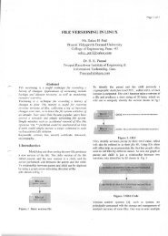
full-scan (Figure 3). In a circuit with a lot <strong>of</strong><br />
sequential feedback and thereby the: length <strong>of</strong> the<br />
sequences cannot be bounded it is not advisable<br />
to use scan flip-flops. In particular parts <strong>of</strong> the<br />
design where timing is critical it can also be<br />
advisable to not using scan flip-flops. In these<br />
cases the design is called partial scan. When this<br />
type <strong>of</strong> design is run through an ATI'G-tool it<br />
may cause loss <strong>of</strong> fault coverage. increased<br />
runtime and an increase in the number <strong>of</strong> tc"S(<br />
vector generated.<br />
3-3. Multiple Scan Chains<br />
If many flip-flops are used in a design a<br />
single scan chain can become too large. It call<br />
take very long time to load each state with a very<br />
long scan chain. Splitting the chain in more scan<br />
chains can solve this. The trade-<strong>of</strong>fs <strong>of</strong> this<br />
solution is that multiple scan chain." requires<br />
more dedicated (cest pins. If multiple scan chains<br />
are used the scan chains should have the same<br />
number <strong>of</strong> scan bits as far as possible this IS<br />
called balanced scan chains.<br />
This is the rncst cost efficient method and it<br />
uses the memory more efficient<br />
3.4. Scan Design Rules<br />
The 'e are many rules <strong>of</strong> for designing a<br />
scan-based design among allthcsc four is useful:<br />
• Use only one kind <strong>of</strong> flip.flop in the design.<br />
E.g. D-type:master-slave.<br />
• At least one primary input pin must be<br />
available for test.<br />
• .Every flip-flop clock must be controllable<br />
from primary inputs.<br />
• Avoid synchronous latches, transparent<br />
latches.<br />
• Do not feed clock to data inputs <strong>of</strong> f1ip- flops<br />
4. Built in Self Test<br />
252<br />
iconADELCO 2007<br />
Since circuits become more dense and faster<br />
with smaller size and that the logic-to-pin ratio<br />
on chips is increasing makes the testing <strong>of</strong> logic<br />
morc and more difficult. It takes longer time to<br />
generate test patterns and the patterns consume<br />
lot <strong>of</strong> memory. Often are the designers not aware<br />
<strong>of</strong> the gate-level structure <strong>of</strong> their designs<br />
because it is synthesized in VHDL hardware<br />
description languages. Therefore it has becoming<br />
interesting to implement different kind <strong>of</strong> logic<br />
in the design so it can test itself so called BIST.<br />
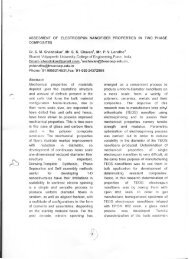
Figure 4. Built in self test (3]<br />
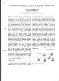
The idea <strong>of</strong> BIST is to implement test<br />
pattern generation and response analyzing and<br />
even fault analyzing together with the chip. BIST<br />
(Figure 4) can be categorized in different ways:<br />
Online IlIST: Testing is done during normal<br />
operation<br />
• Concurrent testing - detects faults while<br />
system is doing normal functions..<br />
e Nun-Concurrent testing - detects faults<br />
while system is in idle mode.<br />
Offline BIST: System is brought 10 a test<br />
mode<br />
e. functional testing - tests the system at a<br />
high level <strong>of</strong> function.<br />
e Structural testing - detects structural faults<br />
<strong>of</strong> the system.<br />
4.1. BIST Pattern Generation