Ross-Tech VAG-COM Data Logging and Graphing ... - VAGLinks.com
Ross-Tech VAG-COM Data Logging and Graphing ... - VAGLinks.com
Ross-Tech VAG-COM Data Logging and Graphing ... - VAGLinks.com

You also want an ePaper? Increase the reach of your titles
YUMPU automatically turns print PDFs into web optimized ePapers that Google loves.
Instructions for <strong>Logging</strong> Using the Vag-Com<br />
Note: Vag-<strong>com</strong> logging should be done by someone who is trained, <strong>com</strong>petent, <strong>and</strong> qualified to do so. This only to be<br />
used as a guideline. This also assumes that you have the Vag-<strong>com</strong> cable installed <strong>and</strong> working on your <strong>com</strong>puter.<br />
See Appendix A for <strong>com</strong>mon measuring blocks<br />
See Appendix B for help making Excel charts<br />
See Appendix C for the 2.0T label file<br />
General:<br />
-Safety is extremely important – only do logs when it’s safe to do so.<br />
-Make sure to follow all applicable laws.<br />
-Most logs should be done in a third gear Wide-Open Throttle (WOT) from 2000-6500 rpm. If this cannot be achieved,<br />
then a second gear WOT can be done.<br />
-For the cars equipped with automatics if you have problems with the kick down, then you can press <strong>and</strong> hold either the<br />
up shift paddle (if equipped) or the push <strong>and</strong> hold the shifter upwards when in Tiptronic mode. So, to do a third gear pull,<br />
press <strong>and</strong> hold the up shift when you are in second gear, which would drop you into third gear.<br />
-Make a note of what the ambient temperature is.<br />
-Whenever you log, make sure to log RPMs, if needed.<br />
-Certain modules such as the LCT module would conflict with the Vag-<strong>com</strong> <strong>and</strong> should be turned off before using the<br />
Vag-<strong>com</strong>.<br />
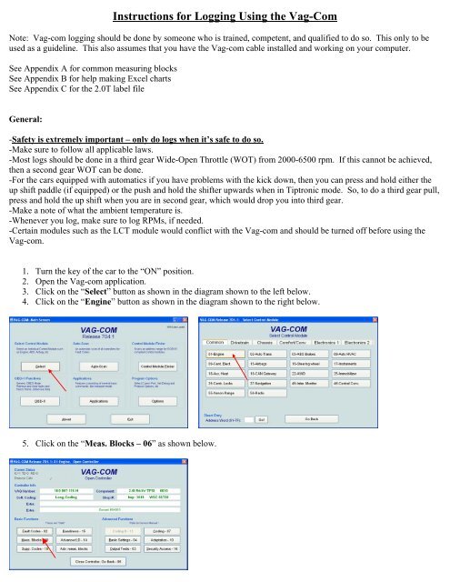
1. Turn the key of the car to the “ON” position.<br />
2. Open the Vag-<strong>com</strong> application.<br />
3. Click on the “Select” button as shown in the diagram shown to the left below.<br />
4. Click on the “Engine” button as shown in the diagram shown to the right below.<br />
5. Click on the “Meas. Blocks – 06” as shown below.
6. A screen like the one below should <strong>com</strong>e up. You can select what blocks you want to measure <strong>and</strong> then hit the<br />
“GO” button. You can log up to 3 measuring blocks at once.<br />
**Tip: You can use the “Turbo” button to increase the sample rate. Also logging less measuring blocks will result in a<br />
higher sample rate. **<br />
7. Hit the “Log” button to start logging as shown (left). You will see a prompt for the file name (right). Vag-<strong>com</strong> will<br />
give you a default name, which can be changed if you’d like. Then press the “Start” button (right) to start logging.<br />
8. You can use the “Marker” button to mark when you start a run, or what type of run it is (i.e. for a 3 rd gear pull, you<br />
can press the marker button three times. Once you are finished logging, press the “Stop” button. Once you are finished<br />
logging, press the “Done, Close” button.
9. Instead of using the Measuring blocks, you can also use the Advanced measuring blocks which allows you to pick <strong>and</strong><br />
choose each <strong>com</strong>ponent you want to log. Select the “Adv. Meas. Blocks” button.<br />
10. Check the items you want to log in the red oval below. Be sure to log RPM. <strong>Logging</strong> is similar as Steps 7 & 8 above.
Appendix A – Common Items to Log<br />
You can look at the label file for your car. This will tell you what can be logged. This is the label file for the 2.0T FSI<br />
engine:<br />
http://www.ross-tech.<strong>com</strong>/vag-<strong>com</strong>/download/label-files/06F-907-115-AXX.lbl (Also in Appendix C)<br />
Generally speaking, to diagnose a problem, I’d start with logging the following Measuring Blocks (MB):<br />
-MB 003,020,115<br />
-MB 002,106,118<br />
You can substitute other MB’s as you see fit.<br />
Common logged items are as follows:<br />
**Note that some items might not be applicable to your car. Please refer to the label file. **<br />
Please note that some readings are shown in more than one Measuring Block (MB)<br />
Boost Pressure: MB 115<br />
-For boost, you should note the actual pressure with the engine off. This would be the atmospheric pressure (shown<br />
circled in red below). As a check, the engine speed arrowed in red below should read “0”. If you are near sea level, then<br />
you can use 1000mbar as an approximate atmospheric pressure.<br />
-Boost Pressure (actual) is the pressure actually seen by the MAP sensor. You should never see a value below<br />
atmospheric pressure since the MAP sensor is located upstream of the throttle body on the 2.0T engine.<br />
-Boost Pressure (specified) is what the engine requests <strong>and</strong> you will see vacuum pressure for specified boost.<br />
-Sometimes, it is useful to log both values.<br />
-Once you get the boost data in PSI, simply use the following equation to calculate boost<br />
(logged boost – atmospheric pressure) * .0145<br />
Fuel Rail Pressure: MB 106<br />
This is the pressure that the fuel is being injected into the <strong>com</strong>bustion chamber. You could run into issues if it gets much<br />
below 100 bar.
Air/Fuel Ratio: MB 031<br />
The 2.0T has a wideb<strong>and</strong> o2 sensor which reads in lambda. Only the front o2 sensor is pertinent in tuning, the rear is for<br />
emissions purposes only. Multiply the lambda value by 14.7 to get the Air/Fuel Ratio.<br />
Timing: MB 011<br />
-Displays the timing angle.<br />
Timing pull: MB 020<br />
-Displays timing pull. This affects Timing (MB 011) above. It is important to note that a lot of timing pull does not<br />
necessarily mean there is a problem.<br />
Mass Air Flow: MB 002<br />
-This is the amount of air that’s <strong>com</strong>ing into the engine. Please note that changing the cross-sectional area of the MAF<br />
housing at the MAF sensor will affect the MAF reading. It is not re<strong>com</strong>mended to change the cross-sectional area unless<br />
you have programming to <strong>com</strong>pensate for it.<br />
Intake Air Temperature (IAT): MB 118<br />
-Self explanatory. It is a good idea to log before <strong>and</strong> after an aftermarket FMIC install.<br />
Torque: MB 120<br />
-The torque calculated is a theoretical value. You can calculate HP using this torque value <strong>and</strong> RPM value.<br />
-You can use the dyno spreadsheet here:<br />
http://www.ross-tech.net/vag-<strong>com</strong>/examples/Block_120_Tutorial.xls<br />
-Some people have reported that the torque value is not accurate for chipped cars, so be careful if you do decide to use<br />
this tool.<br />
Fuel Trims: MB 032<br />
-These values can be checked with the engine off.<br />
-Generally speaking, you’d want to be within ±10% if you’re stock. If you’re modded, then the mods might have some<br />
affect on the fuel trims. If your fuel trims are way out of whack then you might get a DTC <strong>and</strong>/or a CEL.<br />
-You can read more about fuel trims here:<br />
http://wiki.ross-tech.<strong>com</strong>/index.php/Fuel_Trim_Info<br />
Exhaust Gas Temperature (EGT): MB 112<br />
-This tells you the temperature at the front o2 sensor as well as projected EGT.<br />
Coolant temperature: MB 004<br />
-This tells you the actual coolant temperature. This could be slightly different then the pseudo coolant temperature gauge<br />
on the dash as the gauge on the dash has a huge dead zone where it will read 190°F.<br />
Voltage Supply: MB 004<br />
-Self explanatory.<br />
Vehicle speed: MB 005<br />
-Tells you the actual vehicle speed. The speed displayed on the speedometer may be off.<br />
Misfire counter: MB 015 & 016<br />
-This could be useful if you suspect that you have misfires.<br />
Wastegate (N75) Duty Cycle: MB 118<br />
Oil temperature: MB 134
Appendix B: Making Graphs Using Excel<br />
1. Using Windows Explorer, find <strong>and</strong> open the log file(s) that you created using the Vag-<strong>com</strong>. They are .CSV Files. If<br />
you open them using Excel, then go to the “File” menu <strong>and</strong> select “Open”. Then you may have to go to the “Files of<br />
type” <strong>and</strong> select “All Files”.<br />
2. Once you open the file, I’d suggest that you resave it as an .XLS file right away.<br />
3. I have deleted the non-related data points to make it easier to see what you’re doing. I am using Boost as an example,<br />
but doing other MB’s should be similar <strong>and</strong> easier. I added two columns to calculate the spec’d <strong>and</strong> actual boost in gauge<br />
pressure in PSI. Note that the 990 is the atmospheric pressure as measured earlier. The equation use is: [(logged boost –<br />
atmospheric pressure) * .0145] as discussed above (see left). Apply the same formula for both spec’d <strong>and</strong> actual (see<br />
result right).
4. Hit the “Insert” toolbar, <strong>and</strong> choose “Chart”. Note, you may have to hit the two down arrows if you don’t see the<br />
Chart option. The chart wizard (right) should pop up. Under “Chart type” select “Line”, then hit “Next” (see right)<br />
5. The screen (left) should pop up. Choose the “Series” tab, <strong>and</strong> you should see something like the screen in the middle.<br />
Hit the “Add” button (middle screen). The screen should look like the right screen.<br />
6. In the “Name” box label it as “Specified Boost”. Then click on the box to the far right of the “Values” box <strong>and</strong> select<br />
the specified boost values.
7. The “Source <strong>Data</strong> – Values” prompt will <strong>com</strong>e up. Select the values you want to use. Hold down the shift key to<br />
select multiple values. Select the button on the far right of the prompt to accept the values <strong>and</strong> close the prompt.<br />
8. Click the “Add” button to add another series. Do Steps # 7 & 8 for the actual boost. The screen should now look like<br />
the one below. Then click on the box to the far right of the “Category (X) axis labels:” as shown below. Follow the<br />
similar procedure in Step #7 to select the RPM values.<br />
9. The graph should now resemble a boost graph (left). Click on the “Next” button. The screen to the right shows up.<br />
Then, enter the values as shown (right), <strong>and</strong> hit “Finish”
10. The graph is now <strong>com</strong>plete. If you wish, you may change the scaling. Click on any of the boost values to open the<br />
“Format Axis” dialog box, <strong>and</strong> click on the “Scale” Tab.<br />
11. Change the scaling to whatever you see fit. You can also change the scaling of the RPMs by clicking on any of the<br />
RPM values (not shown).<br />
12a. If you have the full version of Adobe Acrobat, then you can use it to print the chart to PDF. Just select the graph <strong>and</strong><br />
hit the Print button. I find that this is gives the best image. You can crop part of the image if you wish. Once you are<br />
satisfied, then in Acrobat, go to File>Save As, <strong>and</strong> save as a .JPG file (not shown).
12b1. If you do not have the full version of Acrobat, then make sure the whole graph is on the screen, <strong>and</strong> hit the “Print<br />
Screen” button on your keyboard (not shown). Then open MS Paint, <strong>and</strong> go to the “Edit” menu, <strong>and</strong> select “Paste”. Use<br />
the select icon (looks like a dashed rectangle), <strong>and</strong> select the graph as shown below.<br />
12b2. Go to the “Edit” menu <strong>and</strong> select “Cut”. Then go to the “File” menu <strong>and</strong> select “New”. When asked to save<br />
changes, select “No”. Then go to the “Edit” menu <strong>and</strong> select “Paste”.<br />
12b3. Go to the “File” menu again, <strong>and</strong> select “Save As”
12b4. In the “Save As” dialog box, select “JPEG” <strong>and</strong> enter a file name <strong>and</strong> location.<br />
13. Use a photo host such as http://photobucket.<strong>com</strong>/ to upload the image <strong>and</strong> use IMG tags to post the image into a<br />
thread. For example, say the http://photobucket.<strong>com</strong>/blah/boost.jpg, the img tags should look like:<br />
[IMG]http://photobucket.<strong>com</strong>/blah/boost.jpg[/IMG]
Appendix C: 2.0T FSI Label File<br />
; <strong>VAG</strong>-<strong>COM</strong> Label File<br />
;<br />
; Audi A3 (8P) / Audi A4 (8E) / Audi A6 (4F) / Audi TT (8J)<br />
; Seat Altea/Toledo (5P) / Seat Leon (1P) / Skoda Octavia (1Z)<br />
; VW Eos (1F) / VW Golf/Jetta (1K) / VW Passat (3C) / VW Touran (1T)<br />
;<br />
; Component: Engine (#01) - AXX/BGB/BPJ/BPY/BWA<br />
;<br />
; P/N: ???-9??-115-???<br />
;<br />
; includes measuring blocks <strong>and</strong> selective output test<br />
;<br />
; This file is part of a redirection package,<br />
; make sure you have all of the following files.<br />
;<br />
; 1K-01.LBL<br />
; 1P-01.LBL<br />
; 1Z-01.LBL<br />
; 3C-01.LBL<br />
; 4F-01.LBL<br />
; 8E-01.LBL<br />
; 8P-01.LBL<br />
; 06F-907-115-AXX.LBL (2.0l TE @ 200 HP - AXX/BGB/BPJ/BPY/BWA)<br />
;<br />
; created on 17/Apr/2005 by Sebastian Stange (Sebastian@<strong>Ross</strong>-<strong>Tech</strong>.<strong>com</strong>)<br />
;<br />
; last modification: 25/Jul/2006<br />
;<br />
; requires <strong>VAG</strong>-<strong>COM</strong> 602.3 or newer<br />
;<br />
;<br />
;---------------------------------------------------<br />
;<br />
; measuring block information<br />
;<br />
;---------------------------------------------------<br />
;<br />
;<br />
001,1,Basic Functions<br />
001,1,Engine Speed<br />
001,2,Coolant,Temperature,Specification: 80...115 °C<br />
001,3,Lambda,Regulator<br />
001,4,Basic Setting,Requirements,see labelfile<br />
; 1xxxxx-x - Coolant temperature below 80 °C<br />
; x1xxxx-x - Engine speed below 2000 RPM<br />
; xx1xxx-x - Throttle valve closed<br />
; xxx1xx-x - Lambda regulation correct<br />
; xxxx1x-x - State of idle<br />
; xxxxx1-x - A/C system <strong>com</strong>pressor deactivated<br />
; xxxxxx-1 - No malfunction detected by Self-Diagnosis<br />
;<br />
002,0,Basic Functions<br />
002,1,Engine Speed<br />
002,2,Engine Load<br />
002,3,Injection,Timing<br />
002,4,Intake Air Mass<br />
;<br />
003,0,Basic Functions<br />
003,1,Engine Speed<br />
003,2,Intake Air Mass<br />
003,3,Throttle Drive,Angle Sensor 1,for EPC (G187) | Display Range: 0...100 %<br />
003,4,Ignition,Timing Angle
;<br />
004,1,Engine Speed<br />
004,2,Voltage Supply,,Specification: 12.0...15.0 V<br />
004,3,Coolant,Temperature,Specification: 80...115 °C<br />
004,4,Intake Air,Temperature,Specification: -40.0...+140.0 °C<br />
;<br />
005,0,Basic Functions<br />
005,1,Engine Speed<br />
005,2,Engine Load<br />
005,3,Vehicle Speed,,Specification: 0 km/h<br />
005,4,Load Status,,Display Range: Idle/Partial Throttle/Wide Open Throttle (WOT)/Enrichment/Deceleration<br />
;<br />
006,0,Basic Functions<br />
006,1,Engine Speed<br />
006,2,Engine Load<br />
006,3,Intake Air,Temperature,Specification: -40.0...+140.0 °C<br />
006,4,Heights Correction,Factor<br />
;<br />
007,1,Engine Speed<br />
007,2,Engine Load<br />
007,3,Engine Coolant,Temperature,Specification: -40...+140 °C<br />
007,4,Operating Mode,,See Label File<br />
; x00xxxx? = Homogenous (Lambda = 1)<br />
; x00xxx?x = Homogenous (Lean)<br />
; x00xx?xx = Homogenous/Stratified<br />
; x00x?xxx = Stratified<br />
; x00?xxxx = Stratified (CAT Heating)<br />
; ?00xxxxx = Knock Protection<br />
;<br />
009,1,Engine Oil,Level<br />
009,2,Engine Oil,Warning Barrier<br />
009,3,Fuel Consumption,Signal<br />
009,4,Consumption,Equivalent<br />
;<br />
010,0,Ignition<br />
010,1,Engine Speed<br />
010,2,Engine Load<br />
010,3,Throttle Drive,Angle Sensor 1,for EPC (G187) | Display Range: 0...100 %<br />
010,4,Ignition,Timing Angle<br />
;<br />
011,1,Engine Speed<br />
011,2,Engine Coolant,Temperature<br />
011,3,Intake Air,Temperature,Specification: -40...+140 °C<br />
011,4,Timing Angle,(current Value)<br />
;<br />
014,1,Engine Speed<br />
014,2,Engine Load<br />
014,3,Misfire,Sum Counter<br />
014,4,Misfire,Recognition<br />
;<br />
015,0,Misfire Recognition<br />
015,1,Cylinder 1<br />
015,2,Cylinder 2<br />
015,3,Cylinder 3<br />
015,4,Malfunction,Recognition,Display Range: activated/blocked<br />
;<br />
016,0,Misfire Recognition<br />
016,1,Cylinder 4<br />
016,4,Malfunction,Recognition,Display Range: activated/blocked<br />
;<br />
018,1,Lower,RPM Barrier<br />
018,2,Upper,RPM Barrier<br />
018,3,Lower,Load Barrier<br />
018,4,Upper,Load Barrier<br />
;<br />
020,0,Ignition (Knock Control - Cyl 1 - 4)
020,1,Cylinder 1 Ignition,Angle Delay<br />
020,2,Cylinder 2 Ignition,Angle Delay<br />
020,3,Cylinder 3 Ignition,Angle Delay<br />
020,4,Cylinder 4 Ignition,Angle Delay<br />
;<br />
022,0,Ignition (Knock Control - Cyl 1 && 2)<br />
022,1,Engine Speed<br />
022,2,Engine Load<br />
022,3,Cylinder 1 Ignition,Angle Delay<br />
022,4,Cylinder 2 Ignition,Angle Delay<br />
;<br />
023,0,Ignition (Knock Control - Cyl 3 && 4)<br />
023,1,Engine Speed<br />
023,2,Engine Load<br />
023,3,Cylinder 3 Ignition,Angle Delay<br />
023,4,Cylinder 4 Ignition,Angle Delay<br />
;<br />
028,0,Knock Sensor Test (Short Trip)<br />
028,1,Engine Speed<br />
028,2,Engine Load<br />
028,3,Coolant,Temperature (G69)<br />
028,4,Result,,Specification: Test ON/Test OFF/Sys. OK/Sys. not OK<br />
;<br />
B028,0,Ignition (Knock Sensor Test - Short Trip)<br />
; "Activate" Basic Setting<br />
; Firmly press Brake Pedal <strong>and</strong> Throttle Pedal at once<br />
; Engine Speed increases to 2200 RPM automatically > Field 4 = Test ON<br />
; Wait until Field 4 shows "Sys. OK"<br />
B028,1,Engine Speed,(G28)<br />
B028,2,Engine Load<br />
B028,3,Coolant,Temperature (G69)<br />
B028,4,Result,,Range: Test ON/Test OFF/Sys. OK/Sys. not OK\nSpecification: Sys. OK<br />
;<br />
030,0,Oxygen Sensor Status<br />
030,1,Bank 1,Sensor 1,Specification: 111<br />
; 1xx - Lambda sensor heating on<br />
; x1x - Lambda sensor ready<br />
; xx1 - Lambda regulation active<br />
030,2,Bank 1,Sensor 2,Specification: 110<br />
; 1xx - Lambda sensor heating on<br />
; x1x - Lambda sensor ready<br />
; xx1 - Lambda regulation active<br />
;<br />
031,0,Lambda Regulation (Constant Operation of Lambda Probes)<br />
031,1,Lambda Sensor,Current Value<br />
031,2,Lambda Sensor,Specified Value<br />
;<br />
032,0,Lambda Regulation<br />
032,1,Lambda (Idle),Self-Adaptation<br />
032,2,Lambda (Partial),Self-Adaptation<br />
;<br />
033,0,Lambda Regulation<br />
033,1,Bank 1,Lambda Control<br />
033,2,Bank 1 Voltage,of Oxygen Sensors<br />
;<br />
034,0,Lambda Regulation (befor Catalyst - Basic Setting: Aging Check)<br />
034,1,Engine Speed<br />
034,2,Catalytic Converter,Temperature<br />
034,3,Period,Duration Sensor<br />
034,4,Result,Lambda Aging,Display Range: Test ON/Test OFF/B1-S1 not OK/B1-S1 OK<br />
;<br />
B034,0,Lambda Control (Aging Check: Bank 1 Sensor 1)<br />
; "Activate" Basic Setting<br />
; Firmly press Brake Pedal <strong>and</strong> Throttle Pedal at once<br />
; Engine Speed increases automatically > Field 4 = Test ON<br />
; Wait until Field 4 shows "B1-S1 OK"
B034,1,Engine Speed,(G28)<br />
B034,2,Catalytic Converter,Bank 1 Temp.<br />
B034,3,Dynamic Factor,Bank 1 Sensor 1<br />
B034,4,Result,Lambda Aging,Range: Test ON/Test OFF/B1-S1 not OK/B1-S1 OK\nSpecification: B1-S1 OK<br />
;<br />
036,1,Bank 1 Sensor 2,Sensor Voltage<br />
036,2,Bank 1 Sensor 2,Result,Specification: Test ON/Test OFF/B1-S2 OK/B1-S2 not OK<br />
;<br />
B036,0,Lambda Control (Sensor Readiness - After Catalyst)<br />
; "Activate" Basic Setting<br />
; Firmly press Brake Pedal <strong>and</strong> Throttle Pedal at once<br />
; Engine Speed increases automatically > Field 4 = Test ON<br />
; Wait until Field 4 shows "B1-S2 OK"<br />
B036,1,Sensor Voltage,Bank 1 Sensor 2<br />
B036,2,Result,Lambda Availability,Range: Test ON/Test OFF/B1-S2 not OK/B1-S2 OK\nSpecification: B1-S2 OK<br />
;<br />
037,1,Engine Load<br />
037,2,Bank 1 Sensor 2,Voltage<br />
037,3,Bank 1 Oxygen,Sensor Value<br />
037,4,Result,,Specification: Test ON/Test OFF/Sys. OK/Sys. not OK<br />
;<br />
B037,0,Lambda Control (Delta Lambda Bank 1)<br />
; "Activate" Basic Setting<br />
; Firmly press Brake Pedal <strong>and</strong> Throttle Pedal at once<br />
; Engine Speed increases automatically > Field 4 = Test ON<br />
; Wait until Field 4 shows "B1-S1 OK"<br />
B037,1,Engine Load<br />
B037,2,Sensor Voltage,Bank 1 Sensor 2<br />
B037,3,Delta Lambda,Bank 1 Sensor 2<br />
B037,4,Result,,Range: Test ON/Test OFF/B1-S1 OK/B1-S1 n.OK\nSpecification: B1-S1 OK<br />
;<br />
041,0,Lambda Regulation (Lambda Probe Heating)<br />
041,1,Resistance,Bank 1 Sensor 1<br />
041,2,Heater Condition,,Specification: Htg.bC.ON<br />
041,3,Resistance,Bank 1 Sensor 2<br />
041,4,Heater Condition,,Specification: Htg.aC.ON<br />
;<br />
043,0,Lambda Regulation (befor Catalyst - Basic Setting)<br />
043,1,Engine Speed<br />
043,2,Catalytic Converter,Temperature<br />
043,3,Bank 1 Sensor 2,Voltage<br />
043,4,Result,Lambda Aging,Display Range: Test ON/Test OFF/B1-S2 not OK/B1-S2 OK<br />
;<br />
B043,0,Lambda Control (Aging Check: Bank 1 Sensor 2)<br />
; "Activate" Basic Setting<br />
; Firmly press Brake Pedal <strong>and</strong> Throttle Pedal at once<br />
; Engine Speed increases automatically > Field 4 = Test ON<br />
; Wait until Field 4 shows "B1-S2 OK"<br />
B043,1,Engine Speed,(G28)<br />
B043,2,Catalytic Converter,Bank 1 Temp.<br />
B043,3,Lambda Voltage,Bank 1 Sensor 2<br />
B043,4,Result,Aging Check,Display Range: Test ON/Test OFF/B1-S2 OK/B1-S2 n.OK\nSpecification: B1-S2 OK<br />
;<br />
046,0,Lambda Regulation (Basic Setting: Conversion Test)<br />
046,1,Engine Speed<br />
046,2,Catalytic Converter,Temperature<br />
046,3,Amplitude,Behavior<br />
046,4,Result Catalytic,Conversion,Pre-Catalytic Converter (Display Range: Test ON/Test OFF/CatConvB1 not OK/CatConvB1 OK)<br />
;<br />
B046,0,Lambda Control (Catalytic Conversion Test Bank 1)<br />
; Short Trips 034/035/036/037/038/043/044 must be OK<br />
; "Activate" Basic Setting<br />
; Firmly press Brake Pedal <strong>and</strong> Throttle Pedal at once<br />
; Engine Speed increases automatically > Field 4 = Test ON<br />
; Wait until Field 4 shows "CatB1 OK"<br />
B046,1,Engine Speed,(G28)
B046,2,Catalytic Converter,Bank 1 Temp.<br />
B046,3,Catalytic,Conversion Bank 1<br />
B046,4,Result,Cat. Conversion,Range: Test ON/Test OFF/CatB1 OK/CatB1 n.OK\nSpecification: CatB1 OK<br />
;<br />
050,1,Engine Speed<br />
050,2,Engine Speed,(specified)<br />
050,3,Condition,of A/C system,Display Range: A/C-High / A/C-Low<br />
050,4,Operating condition,of A/C Compressor,Display Range: Compr.ON/Compr.OFF<br />
;<br />
051,1,Engine Speed<br />
051,2,Specified,Engine Speed<br />
051,3,Driving mode,,Gear 1...6 (only for automatic)<br />
051,4,Voltage Supply,,Specification: 12.0...15.0 V<br />
;<br />
052,1,Engine Speed<br />
052,2,Engine Speed,(Specified)<br />
052,3,Condition,of A/C system,Display Range: A/C-High / A/C-Low<br />
052,4,Window Heaters<br />
;<br />
053,0,Speed Regulation<br />
053,1,Engine Speed,,Specification: 640...900 RPM<br />
053,2,Engine Speed,(specified),Specification (manual): 670...760 RPM | Specification (automatic): 800...860 RPM<br />
053,3,Voltage Supply,,Specification: 12.0...15.0 V<br />
053,4,Generator Load<br />
;<br />
054,0,Speed Regulation<br />
054,1,Engine Speed<br />
054,2,Load Status,,Display Range: Idle/Partial Throttle/Wide Open Throttle (WOT)/Enrichment/Deceleration<br />
054,3,Sender 2 for,Acc. Pedal Pos.,G79 (Display Range 0...100 %)<br />
054,4,Throttle Drive,Angle Sensor 1,for EPC (G187) | Display Range: 0...100 %<br />
;<br />
055,0,Speed Regulation<br />
055,1,Engine Speed<br />
055,2,Idle Regulator<br />
055,3,Idle Stabilization,Self-Adaptation<br />
055,4,Load Status,,see labelfile<br />
; x0xxx? = A/C Compressor<br />
; x0xx?x = Gear engaged<br />
; x0x?xx = A/C Readiness<br />
; x0?xxx = Rear Window Heater<br />
; ?0xxxx = Front Window Heater<br />
;<br />
056,0,Speed Regulation<br />
056,1,Engine Speed<br />
056,2,Engine Speed,(specified)<br />
056,3,Idle Regulator<br />
056,4,Load Status,,see labelfile<br />
; x0xxx? = A/C Compressor<br />
; x0xx?x = Gear engaged<br />
; x0x?xx = A/C Readiness<br />
; x0?xxx = Rear Window Heater<br />
; ?0xxxx = Front Window Heater<br />
;<br />
057,1,Engine Speed<br />
057,2,Engine Speed,Specified Value<br />
057,3,A/C Compressor<br />
057,4,Duty Cycle,Pressure Sensor,Torque A/C Compressor<br />
;<br />
060,0,Speed Regulation (Basic Setting: Throttle Body Adaptation)<br />
060,1,Throttle Drive,Angle Sensor 1,for EPC (G187) | Specification: 0...100 %<br />
060,2,Throttle Drive,Angle Sensor 2,for EPC (G188) | Specification: 100...0 %<br />
060,3,Self-Adaptation,Steps Counter<br />
060,4,Result,Throttle Valve Adp.,Display Range: ADP runs/ADP OK/ADP ERROR<br />
;<br />
061,1,Engine Speed<br />
061,2,Voltage Supply,,Specification: 12.0...15.0 V
061,3,Activation Throttle,Position Actuator<br />
061,4,Operating,Condition<br />
;<br />
062,1,Throttle Drive,Angle Sensor 1,for EPC (G187)<br />
062,2,Throttle Drive,Angle Sensor 2,for EPC (G188)<br />
062,3,Throttle Position,Sensor (G79)<br />
062,4,Accelerator Pedal,Position Sensor 2,G185<br />
;<br />
063,0,Speed Regulation (Basic Setting: Kick-Down Adaptation)<br />
063,1,Throttle Position,Sensor (G79),Display Range: 0...100 %<br />
063,2,Accelerator Pedal,Position Sensor 2,G185<br />
063,3,Kick-Down,Switch,Display Range: Kick Down<br />
063,4,Kick-Down,Adaptation,Display Range: ADP runs/ADP OK/ADP ERROR<br />
;<br />
064,1,Potentiometer 1,Lower Adaptation<br />
064,2,Potentiometer 2,Lower Adaptation<br />
064,3,Emergency Air Gap,Potentiometer 1<br />
064,4,Emergency Air Gap,Potentiometer 2<br />
;<br />
066,1,Actual,Driving Speed<br />
066,2,Switch Positions<br />
066,3,Specified,Driving Speed,by Cruise Control System (CCS)<br />
066,4,Switch Positions<br />
;<br />
067,2,CCS Switch,Positions<br />
;<br />
068,1,Engine Speed<br />
068,2,Engine Load<br />
068,3,Driving Mode,,only for automatic transmission<br />
068,4,Converter,Clutch Status<br />
;<br />
070,0,Emission Reduction (TEV - Basic Setting)<br />
070,1,Evap. Emissions,Sol. Valve (Open),Specification: 0...100 %<br />
070,2,Oxygen Sensor,Control Deviation<br />
070,3,Evap. Emissions,Sol. Valve (Flow)<br />
070,4,Result,Evap. Emissions,Display Range: Test ON/Test OFF/TEV OK/TEV not OK<br />
;<br />
080,0,Advanced Control Module Identification I<br />
;<br />
081,0,Advanced Control Module Identification II<br />
081,1,Vehicle Ident.,Number (VIN)<br />
;<br />
082,0,Advanced Control Module Identification III<br />
;<br />
083,0,Advanced Control Module Identification IV<br />
083,1,Primary Vehicle,Ident. Number (VIN)<br />
;<br />
086,1,Readiness Bits<br />
086,2,Cycle-Flags<br />
086,3,Cycle-Flags<br />
086,4,Cycle-Flags<br />
;<br />
087,1,Readiness Bits<br />
087,2,System,Malfunction<br />
087,3,System,Malfunction<br />
087,4,System,Malfunction<br />
;<br />
088,1,System Condition<br />
088,2,System Condition<br />
088,3,System Condition<br />
;<br />
089,0,Trip Recorder<br />
089,1,Distance travelled,with MIL active<br />
089,2,Condition,"Tank Empty",Display Range: OK/too low<br />
;<br />
091,1,Engine Speed
091,2,Intake Camshaft,Duty Cycle<br />
091,3,Camshaft,Adjustment (spec.)<br />
091,4,Camshaft,Adjustment (act.)<br />
;<br />
093,1,Engine Speed<br />
093,2,Intake Camshaft,Duty Cycle<br />
093,3,Phase Position,Bank 1<br />
;<br />
094,0,Camshaft Adjustment (Basic Setting)<br />
094,1,Bank 1 Camshaft,Adjustment,Specification: CAM-ADJ.ON | Display Range: CAM-ADJ.ON/CAM-ADJ.OFF<br />
094,2,Bank 2 Camshaft,Adjustment,Specification: CAM-ADJ.ON | Display Range: CAM-ADJ.ON/CAM-ADJ.OFF<br />
094,3,Diagnostic,Result,Specification: Syst. OK | Display Range: Test OFF/Test ON/Syst.OK/Syst. nOK<br />
;<br />
099,0,Lambda Control Shut-Off (Basic Setting)<br />
099,1,Engine Speed<br />
099,2,Coolant,Temperature,Specification: 80...115 °C<br />
099,3,Lambda Regulator,(before catalyst)<br />
099,4,Status Lambda,Regulation,Display Range: ON/OFF<br />
;<br />
100,1,Readiness Bits,,see labelfile<br />
; 1xxxxxxx - Exhaust Gas Recirculation (EGR)<br />
; x1xxxxxx - Sensor heater<br />
; xx1xxxxx - Oxygen sensors<br />
; xxx1xxxx - A/C system<br />
; xxxx1xxx - Secondary Air Injection (AIR) system<br />
; xxxxx1xx - Activated charcoal system<br />
; xxxxxx1x - Catalytic converter heater<br />
; xxxxxxx1 - Catalytic converter<br />
100,2,Coolant,Temperature<br />
100,3,Time since,Engine Start<br />
100,4,OBD-Status,,see labelfile<br />
; 1-xxxxxx - MIL warning lamp on<br />
; x-1xxxxx - Complete distance<br />
; x-x1xxxx - At least one malfunction detected<br />
; x-xx--1x - Heating cycle ended<br />
; x-xx--x1 - Heating cycle not possible<br />
;<br />
101,1,Engine Speed<br />
101,2,Engine Load<br />
101,3,Median,injection timing<br />
101,4,Intake Air Mass<br />
;<br />
102,1,Engine Speed<br />
102,2,Coolant,Temperature,Specification: -40...+140 °C<br />
102,3,Intake air,temperature<br />
102,4,Median,injection timing<br />
;<br />
103,1,Current,Fuel Pressure<br />
103,2,Fuel Pressure,Regulator<br />
103,3,Adaptation Value,elect. Fuel Pump<br />
103,4,Dem<strong>and</strong> controlled,Fuel Pump Adapt.<br />
;<br />
104,1,Start Engine,Temperature<br />
104,2,Temperature,Adaptation Factor 1<br />
104,3,Temperature,Adaptation Factor 2<br />
104,4,Temperature,Adaptation Factor 3<br />
;<br />
106,1,Fuel Rail,Pressure<br />
106,2,Electrical,Fuel Pump 1<br />
106,3,Electrical,Fuel Pump 2<br />
;<br />
107,1,Engine Speed<br />
107,2,Lambda Controller,Bank 1 Med. Value<br />
107,4,Result Short Trip<br />
;<br />
110,1,Engine Speed
110,2,Coolant,Temperature,Specification: -40...+140 °C<br />
110,3,Median Injection,Timing<br />
110,4,Throttle Valve Angle,(Potentiometer)<br />
;<br />
111,0,Charge Pressure Control<br />
111,1,RPM Range 1<br />
111,2,RPM Range 2<br />
111,3,RPM Range 3<br />
111,4,RPM Range 4<br />
;<br />
112,1,Exhaust Temp.,Bank 1<br />
112,2,Enrichment Factor,Sensor Bank 1<br />
112,3,Exhaust Temp.,Projection<br />
112,4,Median,Exhaust Temp.<br />
;<br />
113,1,Engine Speed<br />
113,2,Engine Load<br />
113,3,Throttle Valve Angle,(Potentiometer)<br />
113,4,Air Pressure,(Atmosphere)<br />
;<br />
114,0,Charge Pressure Control<br />
114,1,Engine Load,(specified)<br />
114,2,Engine Load,(spec. corrected)<br />
114,3,Engine Load,(actual Value)<br />
114,4,Wastegate (N75),Duty Cycle<br />
;<br />
115,0,Charge Pressure Control<br />
115,1,Engine Speed<br />
115,2,Engine Load<br />
115,3,Boost Pressure,(specified)<br />
115,4,Boost Pressure,(actual)<br />
;<br />
116,1,Engine Speed<br />
116,2,Correction Factor,Fuel<br />
116,3,Correction Factor,Coolant Temp.<br />
116,4,Intake Air Temp.,Correction Factor<br />
;<br />
117,0,Charge Pressure Control<br />
117,1,Engine Speed<br />
117,2,Throttle Position,Sensor (G79),Display Range: 0...100 %<br />
117,3,Throttle Drive,Angle Sensor 1,for EPC (G187) | Display Range: 0...100 %<br />
117,4,Boost Pressure,(specified)<br />
;<br />
118,0,Charge Pressure Control<br />
118,1,Engine Speed<br />
118,2,Intake Air,Temperature<br />
118,3,Wastegate (N75),Duty Cycle<br />
118,4,Boost Pressure,(actual)<br />
;<br />
119,0,Charge Pressure Control<br />
119,1,Engine Speed<br />
119,2,Charge Limit<br />
119,3,Wastegate (N75),Duty Cycle<br />
119,4,Boost Pressure,(actual)<br />
;<br />
120,0,Traction Control (TC/ASR)<br />
120,1,Engine Speed<br />
120,2,Engine Load,(specified)<br />
120,3,Engine Load,(actual)<br />
120,4,Status,,Display Range: TC active/TC n.active<br />
;<br />
122,0,Transmission<br />
122,1,Engine Speed<br />
122,2,Engine Load,(specified)<br />
122,3,Engine Load,(actual)<br />
122,4,Status,,Display Range: Torque red./No tor.red.
;<br />
125,0,CAN-<strong>Data</strong>bus Communication (Powertrain)<br />
125,1,Transmission<br />
125,2,Brake Electronics<br />
125,3,Instrument Cluster<br />
125,4,A/C System<br />
;<br />
126,0,CAN-<strong>Data</strong>bus Communication (Powertrain)<br />
126,2,Steering Angle,Sensor (G85)<br />
126,3,Airbag<br />
126,4,Central,Electronics<br />
;<br />
127,0,CAN-<strong>Data</strong>bus Communication (Powertrain)<br />
127,1,All-Wheel-Drive<br />
127,3,Steering Wheel,Electronics<br />
127,4,Brake Booster<br />
;<br />
128,0,CAN-<strong>Data</strong>bus Communication (Powertrain)<br />
128,1,Electrical,Ignition Key<br />
128,2,NOX-Sensor 1<br />
128,3,NOX-Sensor 2<br />
;<br />
129,0,CAN-<strong>Data</strong>bus Communication (Powertrain)<br />
129,2,Oil Temperature,Sensor<br />
129,3,CAN-Gateway<br />
;<br />
130,0,Mapped Cooling<br />
130,1,Coolant temp.,engine outlet,Specification: 80...115 °C<br />
130,2,Cool<strong>and</strong> temp.,radiator outlet,Specification: 0...100 °C<br />
130,3,Thermostat,duty cycle,Specification: 0...100 %<br />
130,4,Result,,Display Range: Test ON/Test OFF/Syst. OK/Syst. n.OK<br />
;<br />
131,0,Mapped Cooling<br />
131,1,Coolant temp.,engine outlet,(actual) Specification: 80...115 °C<br />
131,2,Coolant temp.,engine outlet,(specified) Specification: 0...115 °C<br />
131,3,Cool<strong>and</strong> temp.,radiator outlet,Specification: 0...100 °C<br />
131,4,Thermostat,duty cycle,Specification: 0...100 %<br />
;<br />
132,0,Mapped Cooling<br />
132,1,Coolant,temperature,radiotor outlet<br />
132,2,Temperature,difference,between engine <strong>and</strong> radiator outlet<br />
132,3,Heater supply,potentiometer,Specification (w/o Climatronic): 0.2...4.8 V | Specification (with Climatronic): 0.2...5.1 V<br />
132,4,Cooling,Status<br />
;<br />
134,1,Oil temperature<br />
134,2,Ambient,temperature<br />
134,3,Intake air,temperature<br />
134,4,Engine output,temperature<br />
;<br />
135,1,Radiator output,temperature<br />
135,2,Duty cycle cooling,fan activation 1<br />
;<br />
136,0,Relay for coolant actuation<br />
136,1,Relay 1,,Specification: ON/OFF<br />
136,2,Relay 2,,Specification: ON/OFF<br />
136,3,Auxiliary water,pump condition<br />
136,4,Fan after-run<br />
;<br />
137,0,A/C Requirements<br />
137,1,AC-Input,,Specification: ON/OFF<br />
137,2,Compressor,Condition,Specification: ON/OFF<br />
137,3,High-Pressure Sw.,or A/C-Pressure<br />
137,4,Fan desire,from A/C-System<br />
;<br />
138,1,Engine Start,Temperature<br />
138,2,Mean Engine,Air Mass
138,3,Median,Vehicle Speed<br />
138,4,Result<br />
;<br />
139,1,Engine Coolant,Temperature Diag.<br />
139,2,Actual Integral,Mass Air Flow<br />
139,3,Specified Integral,Mass Air Flow<br />
139,4,Result<br />
;<br />
140,1,Quantity Valve,closing Angle<br />
140,2,Quantity Valve,opening Angle<br />
140,3,Rail Pressure,(actual)<br />
140,4,Quantity Control,Valve Status<br />
;<br />
141,1,High pressure,system adaptation<br />
141,2,Controller Portion<br />
141,3,Total Compression,Volume<br />
141,4,Rail Pressure,(actual)<br />
;<br />
142,1,Voltage,Upper Stop<br />
142,2,Voltage,Lower Stop<br />
142,3,Adaptation,Status<br />
142,4,Adaptation,Condition<br />
;<br />
143,1,Engine Speed<br />
143,2,Engine Load<br />
143,3,Load shift flap,opening angle<br />
143,4,Operating mode,(GDI)<br />
;<br />
166,1,Lambda<br />
166,2,Sensor Voltage,behind cat. conv.<br />
166,3,Integrated Air Mass<br />
166,4,Result<br />
;<br />
167,1,Oxygen Portion<br />
167,2,Diagnostic,Decelerator Count.<br />
167,3,Const. Oxygen,Sens. Correction,value oxygen sensor<br />
167,4,Result<br />
;<br />
200,0,Readiness Code (Automatic "End of Line" Check)<br />
200,1,Status Counter,,Number of Short Trips that still\nneed to be carried out.<br />
200,2,Status<br />
200,3,Status<br />
200,4,Status<br />
;<br />
B200,0,Readiness Code (Automatic "End of Line" Check)<br />
; "Activate" Basic Setting<br />
; On Request: Firmly press Brake Pedal <strong>and</strong> Throttle Pedal at once<br />
; Engine Speed increases automatically<br />
; Wait until "Syst. OK" is shown<br />
B200,1,Status Counter,,Number of Short Trips that still\nneed to be carried out.<br />
B200,2,Status<br />
B200,3,Status<br />
B200,4,Status<br />
;<br />
230,0,Fuel Rail Pressure<br />
230,1,Rail Pressure,(specified)<br />
230,2,Rail Pressure,(actual),Specification (Idle): 25.0 bar\nSpecification (Load): max. 110.0 bar<br />
230,3,Rail Pressure,Difference,Specification: ±5.0 bar<br />
;