n - Fachhochschule Jena
n - Fachhochschule Jena
n - Fachhochschule Jena

You also want an ePaper? Increase the reach of your titles
YUMPU automatically turns print PDFs into web optimized ePapers that Google loves.
<strong>Fachhochschule</strong> <strong>Jena</strong><br />
Fachbereich ET/IT – Studiengang Mechatronik<br />
Vorlesung Sensorik<br />
Faseroptische Sensoren (FOS)<br />
Prof. Dr. Reinhardt Willsch und Dr. Wolfgang Ecke<br />
Institut für Photonische Technologien (IPHT) <strong>Jena</strong>, Germany<br />
Arbeitsgruppe Faseroptische Systeme (e-mail: willsch@ipht-jena.de)<br />
� Physikalisch-technische Wirkprinzipien, faseroptische Komponenten<br />
� Multimode-FOS – intensitäts- und spektral-moduliert<br />
� Monomode-FOS – Interferometrie, Polarimetrie<br />
� Verteilte Sensorsysteme – OTDR-Technik, Raman & Brillouin-Rückstreuung<br />
� Fasergitter-Sensoren – Sensornetzwerke, Multiplextechniken<br />
� Anwendungen – Prozesskontrolle, Energietechnik, Transporttechnik uva.<br />
� Ausblick – biochemische Anwendungen, Marktentwicklung<br />
FOS - 1
Komponenten faseroptischer Sensoren (I)<br />
Lichtquellen und -detektoren (optoelektronische Bauelemente):<br />
- LED und Laserdioden auf GaAlAs-Basis für den sichtbaren und nahen IR-<br />
Spektral-bereich (z.B. 780 nm-Laserdioden der CD-Technik)<br />
- Miniatur-Glühstrahler als breitbandige Quellen (z.B. Halogen-Lampen)<br />
- spezielle Lichtquellen wie Superlumineszenzdioden (für Fasergyroskope),<br />
durchstimmbare Laser, Laserdioden-gepumpte Faserlaser u.a.<br />
- Si-Photodioden und Dioden-Arrays, CCD-Zeilen u.a. Photodetektoren<br />
FOS - 2
Komponenten faseroptischer Sensoren (II)<br />
Lichtwellenleiter:<br />
- Multimodenfasern (Stufen- oder Gradientenindex)<br />
- Monomodefasern (normal oder hochdoppelbrechend mit<br />
polarisationserhaltenden Eigenschaften)<br />
- Fasern mit speziellen Dotierungen (z.B. Seltene Erden) oder Überzügen<br />
(Metalle, magnetostriktive oder piezoelektrische Materialien u.a.)<br />
- Fasern aus Spezialgläsern (IR-durchlässige Chalkogenid- oder<br />
Fluoridglasfasern, poröse Borosilikatglasfasern u.a.) oder optisch<br />
transparente Polymere<br />
- Fasern mit hoher numerischer Apertur, mit Mehrfachkern oder spezieller<br />
Kern- bzw. Mantelgeometrie, Faserbündel, u.a.<br />
FOS - 3
Komponenten faseroptischer Sensoren (III)<br />
Miniaturisierte optische Bauelemente und Verbindungstechnik:<br />
- passive BE wie Koppler/Strahlteiler, Polarisatoren, Filter/Multiplexer, Linsen<br />
u.a.<br />
- aktive BE wie Modulatoren für Intensität, Phase, Polarisation oder<br />
Frequenz u.a.<br />
=> Faseroptik, Integrierte Optik oder Mikrooptik sowie Kombination<br />
verschiedener Mikrotechnologien und Aufbau- und Verbindungstechniken -><br />
Mikrosystemtechnik<br />
=> Mikromechanik (z.B. in Si geätzte V-Nuten zur Faserpositionierung oder<br />
Mikroresonatoren, -membranen u.a. als Sensorelemente)<br />
FOS - 4
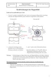
Mikromechanische Silizium-Komponenten<br />
für die Fasersensorik<br />
Sensorelement mit 2 Spiegeln für<br />
faseroptische Transmissionssensoren<br />
(Lichtschranken, Absorption bzw.<br />
Streuung in Gasen oder Flüssigkeiten<br />
Sensorelement mit reflektierender<br />
Zunge für faseroptische Vibrationsbzw.<br />
Beschleunigungssensoren<br />
FOS - 5
Typen von Lichtleitfasern<br />
Querschnitt Brechzahl- Eingangs- Wellenausbreitung Ausgangs-<br />
Profil Impuls Impuls<br />
FOS - 6
Advantages of Optical Fiber Sensors<br />
� Immunity against / applicable in<br />
- Strong electromagnetic fields, high voltage<br />
- Explosive or chemically aggressive & corrosive media<br />
- Nuclear / ionizing radiation environment<br />
- High temperature<br />
� Highly sensitive, miniaturized, flexible and lightweight (nano-probes)<br />
� Low-loss and non-interfering signal transmission (remote sensing)<br />
� Multiplexing capability, compatible to optical communication<br />
(sensor networks)<br />
� Embedding in composite materials (smart structures)<br />
FOS - 7
Photo:<br />
CFRP with Embedded Fiber-optic<br />
Strain Sensors<br />
A vision is becoming reality:<br />
Smart Structures with integrated “nervous system”<br />
Laminated carbon fiber reinforced polymer (CFRP) composite material<br />
containing embedded sensing optical glass fiber (Bragg grating array)<br />
FOS - 8
Basic Fiber Sensor Configurations<br />
Single-point sensor Optical fiber<br />
Multi-point (quasi-distributed) sensor<br />
Distributed sensor<br />
Continuous sensing element<br />
Sensing element<br />
Multiple sensing points<br />
FOS - 9
Häufig verwendete Messeffekte<br />
Extrjnsische Multimoden-Fasersensoren:<br />
- Reflexion am Lichtleiterende (bewegliche Spiegel, reflektierende Membranen u.a.)<br />
- Transmission zwischen zwei Lichtleitfasern (bewegliche Masken, Streuung an Teilchen u.a).<br />
- Photolumineszenz (Temperaturabhängigkeit der spektralen Intensitätsverteilung & Abklingzeit)<br />
Intrinsische Multimoden-Fasersensoren:<br />
- Mikrobiegung; Makrobiegung<br />
- Streu-, Absorptions- und Fluoreszenzprozesse in speziell dotierten Fasern bzw. durch<br />
Materialdefekte (Kernstrahlung u.a.).<br />
Interferometrische Fasersensoren:<br />
- Längenänderungen: Thermische Dehnung, mechanische Spannung, Magneto- & Elektrostriktion<br />
- Brechzahländerungen: Thermooptischer Effekt, Photoelastischer Effekt, Magneto- &<br />
elektrooptische Effekte<br />
Polarimetrisehe Fasersensoren:<br />
Änderungen der Doppelbrechung: mechanisch induzierte Doppelbrechung (elastooptischer Effekt),<br />
Faradayeffekt (magnetooptischer Effekt), Pockelseffekt (elektrooptlscher Effekt),<br />
Weitere wichtige Messeffekte:<br />
- der relativistische Sagnac-Effekt<br />
- nichtlineare Streuprozesse (Raman- oder Brillouin-Streuung)<br />
FOS - 10
Optical Fiber Sensors: Measurands<br />
• distance, position, displacement, deformation, strain<br />
• temperature<br />
• pressure, force<br />
• refractive index, liquid level, flow velocity<br />
• rotation rate<br />
• vibration<br />
• magnetic, electric and acoustic fields<br />
• electric current, voltage<br />
• nuclear radiation<br />
• chemical parameters<br />
• biochemical reactions<br />
and other<br />
FOS - 11
Optical Fiber Sensors:<br />
Basic Principle & Scheme<br />
Measurand X modulates (encodes) a parameter P of light guided in the fiber:<br />
E x,y (z,t) = A cos (ωt - kz+δ)<br />
• Intensity / amplitude A<br />
• Wavelength /spectral distribution λ = c 2π / ω<br />
• Optical phase δ<br />
• Polarization E x / E y<br />
• Time dependence t (pulse delay, fluorescence decay, modulation frequency,...)<br />
light source<br />
power supply<br />
transmitting fiber receiving fiber<br />
P o<br />
sensitive<br />
element<br />
(transducer)<br />
Measurand X<br />
P(x)<br />
optoelectronic<br />
detector<br />
S(x)<br />
electronic<br />
signal processing<br />
FOS - 12
Optical Fiber Sensors:<br />
Basic Signal Encoding & Processing Concepts<br />
� Intensity-modulated sensors<br />
- low-cost and simple technical solutions<br />
- poor accuracy & stability (influence of light-source intensity, fiber losses, ..)<br />
→ reference channel ( 2 wavelengths, spectral photometry, ... )<br />
- applications in automation & control (on-off sensors), medicine, and other<br />
� Phase-modulated interferometric sensors<br />
- high-sensitive but expensive and sophisticated technical solutions (e.g. fiber gyro)<br />
- cross-sensitivities ( temperature, ... )<br />
- applications in precision measurement, military (fiber hydrophones), seismic sensing<br />
� Spectral-encoded sensors<br />
- potential for cost-efficient high-performance technical sensors (FBG sensor systems, biochemical<br />
sensing,.) using standard optoelectronic signal processing (mini-spectrometers)<br />
- long-term stability, reproducibility and reliability<br />
- interchangeability (calibration by absolutely defined wavelength scale)<br />
- applications in industrial process control, environmental and structural monitoring, bio-medicine<br />
FOS - 13
Optical Fiber Sensor Systems and their Application<br />
• Intensity-modulated optical fiber sensors<br />
FOS - 14
Principle of Reflective Displacement Sensor<br />
a) 1 fiber + fiber coupler b) 2 parallel fibers<br />
Source, I 0<br />
1<br />
0.8<br />
0.6<br />
0.4<br />
0.2<br />
0<br />
L<br />
2R f<br />
Detector, I(L)<br />
I(L) ~ I 0 ·[R f /(R f + L·NA) ]²<br />
NA=0,25<br />
NA=0,15<br />
0 2 4 6 8 10<br />
L/R f<br />
L<br />
Characteristics<br />
depend on<br />
- Numer. Aperture<br />
- fiber radius<br />
- fiber distance<br />
0 2,5 L/mm 5<br />
FOS - 15
Example of an Intensity Sensor:<br />
Diaphragm Pressure Sensor<br />
Pressure, displacement, etc.<br />
Curves A, B, C:<br />
A: step index B: graded index C: 2 fibres<br />
FOS - 16
Application:<br />
Medical In-vivo Brain Pressure Sensor<br />
Fa. Camino/USA<br />
FOS - 17
Fiber-Optic Medical In-vivo<br />
Brain Pressure Sensing<br />
Fa. Camino/USA<br />
FOS - 18
Fiber-Optic Medical In-vivo<br />
Heart Pressure Sensing<br />
Fa. Camino/USA<br />
FOS - 19
Principle of Micro-Bending Fiber-Optic Sensors<br />
Optical transmission losses (leaky modes) caused by periodic fiber bending<br />
Interference of core modes and cladding modes:<br />
Core modes (e.g., n eff = n c ) ⇒ Cladding modes (e.g., n eff = n cl )<br />
Max. sensitivity (losses) at optimal bending period L opt :<br />
(L opt ) -1 = ( λ / n c ) -1 – ( λ / n cl ) -1<br />
L opt mechanical transducer<br />
Cladding, n cl<br />
Core, n c<br />
Example:<br />
n c = 1,460<br />
n cl = 1,459<br />
λ = 0,8 µm<br />
L opt = 0,8 mm<br />
FOS - 20
Technical Micro-Bending Fiber-Optic Sensors<br />
force, pressure<br />
strain<br />
metal wire coiled on optical glass<br />
fiber with optimal bending period<br />
→ distributed intrusion detectors<br />
(Felten&Guilleaume; Herga)<br />
"Optical Strand" strain sensor<br />
(OSMOS DEHA-COM)<br />
FOS - 21
Application of Micro-Bending Sensors:<br />
Structure Monitoring in Civil Engineering<br />
Network of 56 "Optical Strand" fiber-optic micro-bending strain sensors for<br />
structure health monitoring of soccer stadium "Stade de France"<br />
in St. Denis/Paris (OSMOS DEHA-COM GmbH Cologne)<br />
FOS - 22
Optical Fiber Sensor Systems and their Application<br />
• Thin-film Fabry-Perot based extrinsic fiber sensors<br />
FOS - 23
I 0<br />
I R<br />
d, n<br />
Extrinsic Spectrally-Encoded FOS<br />
Using Thin-Film Fabry-Perot Transducers<br />
I T<br />
Partially reflecting mirrors<br />
I R<br />
Λ min~ d, n<br />
Grating<br />
LED<br />
Free Spectral Range > LED spectral width !<br />
λ<br />
Polychromator<br />
CCD line<br />
detector<br />
1 mm<br />
LWL<br />
Fabry-Perot probe<br />
n H<br />
n Low<br />
FOS - 24
Porous Transducer Layers on<br />
Fiber End-Face: Humidity Sensor<br />
Nano-porous thin-film transducer Reflection spectra<br />
H 2 O vapor<br />
Optical fiber<br />
∅≈200 µm<br />
Reflectivity<br />
Wavelength [nm]<br />
1,0<br />
0,5<br />
H 2 0 filled pores<br />
Dry pores<br />
0,0<br />
600 700 800 900 1000<br />
Wavelength [nm]<br />
812<br />
802<br />
792<br />
-90<br />
Sensor characteristic<br />
-60 -30 0 30<br />
Dew point [°C]<br />
FOS - 25
Fiber-Optic Humidity Sensor: Applications<br />
• On-line measurement of residual humidity in gases (natural gas, purified<br />
gases) and in organic liquids<br />
• Measuring range<br />
Dew Point T DP = - 80 °C…+20 °C<br />
= partial pressure p(H 2O) = 10 -2 …10 3 Pa<br />
Natural gas drying station<br />
(German Verbundnetz Gas AG)<br />
Hygrometer (BARTEC GmbH)<br />
Sensor<br />
FOS - 26
T-sensitive Transducer Layers:<br />
Temperature Sensor<br />
• Measuring range: T = -196 °C .. +600 °C (laser micro-welded mounting)<br />
• Resolution: 0,2 %<br />
• Application: gas industry, explosive media,<br />
high-voltage, high-frequency & micro-wave facilities<br />
Typical sensor characteristic<br />
Wavelength [nm]<br />
850<br />
840<br />
830<br />
820<br />
810<br />
800<br />
790<br />
-100 0 100 200 300 400 500 600<br />
Temperature [°C]<br />
Sensor sample<br />
1 cm<br />
FOS - 27
Silicon Micro-Membrane Cavity on<br />
Fiber End-Face: Pressure Sensor<br />
• Measuring ranges: p = 0…1,5 bar…15 bar…50 bar…150 bar<br />
• Resolution: 0,5%<br />
• Application: gas industry, engines, medical engineering, ..<br />
Typical sensor characteristics<br />
Membrane bending [nm]<br />
800<br />
600<br />
400<br />
200<br />
0..1.5 Bar<br />
Measuring range<br />
limited by width of<br />
LED spectrum<br />
0..15 Bar<br />
0..50 Bar<br />
0..150 Bar<br />
0<br />
0 10 20 30 40 50 60<br />
Pressure [Bar]<br />
Sensor sample<br />
Membrane array fabricated on Si wafer<br />
Etched silicon membrane<br />
Anodically bonded<br />
sensor element<br />
Glass substrate<br />
Capillary,<br />
fiber inside<br />
FOS - 28
Optical Fiber Sensor Systems and their Application<br />
• Spectrally encoded sensors<br />
FOS - 29
Fiber-Optic Medical In-vivo<br />
Blood Oxygen Sensing<br />
FOS - 30
Schema: Fa. Asea<br />
Photolumineszenz-Temperatursensor<br />
Wirkprinzip:<br />
Temperaturabhängigkeit<br />
der spektralen<br />
Intensitätsverteilung der<br />
Photolumineszenz eines<br />
GaAlAs-Kristalls<br />
Messprinzip:<br />
2-Wellenlängen-<br />
Verfahren<br />
(Streckenneutralität!)<br />
FOS - 31
Sensorelement Saphirfaser Kollimator Strahlteiler Filter PD Division<br />
Al 2 O 3 - Iridium-<br />
Schutz- Strahler-<br />
Schicht -Schicht<br />
Hochtemperatursensor mit<br />
schwarzem Strahler<br />
λ 2<br />
λ 1<br />
λ 1<br />
λ 2<br />
Strahler-Charakteristik:<br />
E λ δλ=C 1/λ 5 ·[exp(C 2/λT)-1] -1 δλ<br />
C1 = 1,17 W·m²/s<br />
C2 = 0,144 K·m<br />
Sensorauswertung:<br />
T ~ I(λ 1)/I(λ 2)<br />
FOS - 32
Transmissivity<br />
UV Fiber Evanescent Field<br />
Absorption Spectroscopy (EFAS) Sensors<br />
In-situ monitoring of organic pollution (BTEX, PAK) in water, soil or in<br />
atmosphere using sensitive (permeable) optical polymer fiber cladding<br />
1,0<br />
0,8<br />
0,6<br />
0,4<br />
0,2<br />
Xylene<br />
Toluene<br />
Benzene<br />
Petrol<br />
Naphta<br />
250 300 350 400 450<br />
Wavelength [nm]<br />
Claddin<br />
Analyte g<br />
(air,<br />
water)<br />
BTEX (Benzene, Toluene, Ethylbenzene, Xylene)<br />
spectra in water<br />
BTEX detection limits in air<br />
Substance<br />
Detection limit<br />
(ml/m 3 )<br />
Max. allowed<br />
concentration<br />
Benzene 3 1<br />
Toluene 10 50<br />
Xylene 10 100<br />
FOS - 33
UV-EFAS Fiber-Optic<br />
Hydrocarbon Pollution Sensor<br />
• Sensor fiber: ∅ 200 µm silica core / 20 µm thick PDMS cladding (length 1 m)<br />
• Light source: Xe flash lamp<br />
• Spectrometer: MMS (Carl Zeiss), UV MINOS (IPHT)<br />
Scheme<br />
Control unit<br />
Battery<br />
Sensor fiber<br />
Power supply<br />
Sensor probe<br />
Fiber cable<br />
UV-Spectrometer<br />
UV lamp<br />
Test instrumentation<br />
for soil monitoring<br />
FOS - 34
Fiber-Optic UV Absorption Sensing of BTEX Pollution in Water:<br />
Long-Time Field Test in Groundwater Remediation Facility<br />
Transmission<br />
1,0<br />
0,8<br />
0,6<br />
0,4<br />
0,2<br />
0,0<br />
Partner:<br />
DBI Gas- und<br />
Umwelttechnik<br />
GmbH Leipzig<br />
Benzene<br />
Toluene<br />
Xylene<br />
Gasoline<br />
Diesel oil<br />
250 300 350 400 450<br />
Wavelength [nm]<br />
Fiber<br />
coil<br />
FOS - 35
Fiber-Optic Hydrocarbon Sensors:<br />
Application<br />
Calibration of UV spectral sensor using<br />
standard BTEX test liquid:<br />
50% Benzene, 30% Toluene,<br />
5% Ethylbenzene, 15% Xylene,<br />
diluted per 1 l water:<br />
Wavelength [nm]<br />
Application (example):<br />
In-situ filter process control<br />
in a groundwater remediation<br />
facility (Lauchhammer, Sax.)<br />
FOS - 36
Spectral In-situ Nutrient Analysis in Inland<br />
and Sea Water<br />
Analytes ranges Analytical methods Measurement<br />
Nitrate UV spectrophotometer 0,5 – 150 µmol/l NO 3 -<br />
o-Phosphate FIA with fluorescence detection 0,05 –5 µmol/l PO 4 3 -<br />
Ammonium FIA with fluorescence detection 0,1 – 20 µmol/l NH 4 +<br />
Sea-test on board of the ferry „Duchess of Scandinavia“ :<br />
Measurement of Nitrate concentration profile in the North Sea<br />
Ferry route<br />
Harwich (GB)-Cuxhaven (D)<br />
NO 3 -N [µg/l]<br />
500<br />
400<br />
300<br />
200<br />
100<br />
0<br />
Harwich<br />
harbour<br />
Elbe<br />
estuary<br />
0 2 4 6 8 12 14 16 18<br />
Journey tim e [h]<br />
Measuring data: Institute for Costal Research, GKSS, 01.06/02.06.2006<br />
FOS - 37
Optical Fiber Sensor Systems and their Application<br />
• Single mode fiber sensors - interferometric sensors<br />
FOS - 38
Laser<br />
Principle of Michelson Interferometer<br />
Linearly<br />
polarised<br />
laser mode<br />
Beam<br />
combining<br />
∆φ = (4π/λ0)·(n∆L+L∆n) ·2<br />
Photo<br />
detector<br />
Reflector<br />
Beam<br />
splitting<br />
L 0<br />
Beam splitter Reflector<br />
When does interference<br />
take place?<br />
• Coherence, i.e., defined<br />
phase relations: Path<br />
difference ∆L < coherence<br />
length<br />
L c ~ λ 0 2 /δλ (δλ spectral width)<br />
• Equal states of polarisation<br />
(superposition of electric field<br />
vectors !)<br />
• Almost equal wavelengths<br />
(frequency difference occurs<br />
as intensity modulation<br />
frequency !)<br />
FOS - 39
• Michelson<br />
- 2-beam interference<br />
- reflection type<br />
• Mach-Zehnder<br />
- 2-beam interference<br />
- transmission type<br />
• Fabry-Perot<br />
- multiple-beam interference<br />
- resonator type<br />
• Sagnac<br />
- ring interferometer<br />
- counter-propagating beams<br />
- relativistic effect<br />
- rotation sensor (fiber gyro)<br />
Types of Fiber-Optic Interferometers<br />
Laser<br />
Detector<br />
Laser<br />
Coupler<br />
Detector Coupler<br />
Parameter X<br />
Transducer<br />
X=f (L,n)<br />
Laser Coupler Coupler<br />
Laser<br />
Detector<br />
Coupler<br />
Parameter X<br />
Transducer<br />
X=f (L,n)<br />
Mirror<br />
Parameter X<br />
Transducer<br />
X=f (L,n)<br />
Mirror<br />
Detector<br />
Detector<br />
Fibre coil<br />
Parameter: Rotation<br />
Mirror<br />
Mirror<br />
FOS - 40
Application of Fiber-Optic Interferometers<br />
• seismic sensors, strain-wave measurement<br />
• hydrophones and hydrophone arrays, microphones<br />
• Atomic Force Microscopes (AFM)<br />
• rotation sensors (gyroscopes)<br />
• magnetic field sensors<br />
• electric current sensors (polarization-mode interferometry)<br />
• fiber grating interferometric strain sensors (extensometers)<br />
• laser wavelength stabilization<br />
Examples:<br />
• high temperature sensor (Fabry-Perot interferometer)<br />
• seismometer for deep bore-holes (Michelson interferometer)<br />
• rotation sensor / gyroscope (Sagnac interferometer)<br />
FOS - 41
Deep Borehole Fiber-Optic Seismometer<br />
Technical parameters of<br />
interferometric sensor system:<br />
max. operational temperature 300 °C<br />
Fibre lead length >10 km<br />
Path length resolution < 10 pm/√Hz<br />
Frequency range 0.1 .. 30 Hz<br />
Measuring range ± 1mm<br />
Laser wavelength 1309 nm<br />
Dimensions ∅ 65 mm<br />
length 215 mm<br />
Technical parameters of<br />
seismic sensor:<br />
3 components in 54° geometry<br />
max. operational temperature 260°C<br />
Eigen resonance 2.5Hz<br />
Attenuation 0.5<br />
from DFB laser<br />
Polyimide coated<br />
single mode<br />
optical fibre<br />
Splice<br />
Collimator<br />
f = 6.3 mm<br />
Frame<br />
Damper<br />
Pivot<br />
54.7°<br />
Feder<br />
(Hochtempera<br />
aus de<br />
Seismische<br />
Seismic<br />
mass Masse<br />
High Hochtemperatur-<br />
temperature<br />
spring<br />
to photo detector<br />
Single mode fibre-optic<br />
coupler 50:50<br />
(IPHT high temperature<br />
version)<br />
Fibre end-face,<br />
8° angled<br />
90° prism<br />
Reflector<br />
sphere<br />
Reflektor ø<br />
Hebelarm<br />
Cantilever<br />
FOS - 42
Scheme of Fiber-Optic 3-Axes<br />
Seismic Sensor System<br />
Monochromatic interferometry using wavelength modulation:<br />
FOS - 43
Seismic Deep Borehole Sensor System -<br />
Photograph<br />
3 axes in 54° geometry<br />
FOS - 44
Seismic Sensing: Measurement Example<br />
Measurement of Iran earthquake May 10, 1997 (Mb = 7.1)<br />
seismic measuring station Moxa/Germany<br />
Seismic movement [µm/s]<br />
Time [08:04 GMT + sec]<br />
FOS - 45
Fiber-Optic Hydrophone<br />
(Michelson-Interferometer)<br />
Naval Research Laboratory, Washington DC, USA<br />
FOS - 46
Measurand:<br />
Extrinsic Fiber-Optic<br />
Fabry-Perot Interferometer<br />
Width of air gap, which changes with strain and/or temperature<br />
FOS - 47
Fiber-Optic Temperature Sensor<br />
(Fabry-Perot Interferometer)<br />
Basic<br />
scheme, example of temperature sensor for high temperatures ≥2000 °C:<br />
FOS - 48
Fiber-Optic Sagnac Interferometer<br />
Gyroscope (Principle)<br />
δϕ s = 8πAN Ω / (λc)<br />
A – Area of fibre coil<br />
N – Number of fibre windings<br />
Ω – Angular velocity<br />
c – Light velocity<br />
Example:<br />
N = 800, R =10 cm (L = 500 m)<br />
λ = 0,8 µm, Ω =1°/h<br />
δϕ s = 13 µrad<br />
FOS - 49
Block Scheme of Fiber-Optic Gyroscope<br />
FOS - 50
Bias stability < 1 °/h<br />
Noise < 10 °/h/√Hz<br />
Range ± 200 °/s<br />
Scale factor error<br />
< 400 ppm<br />
Parameters of Fiber-Optic Gyro<br />
Teldix MKF4 (1993)<br />
Dimensions 100x70x80 mm³<br />
Operational temperature<br />
-30..70 °C<br />
FOS - 51
1975<br />
1985<br />
1995<br />
2005<br />
Time Scale of Development of<br />
Fiber-Optic Gyroscopes<br />
First publication<br />
Lab proto @ 0.01 º/hr<br />
First commercial applications<br />
(Boeing 777)<br />
Broader Applications:<br />
(Subsea, automotive, etc)<br />
Photo: KVH Industries<br />
FOS - 52
Polarimetrischer Stromsensor<br />
(Magnetooptischer Effekt)<br />
FOS - 53
Optical Fiber Sensor Systems and their Application<br />
• Distributed Raman & Brillouin / OTDR<br />
fiber sensor systems<br />
FOS - 54
Distributed Fiber-Optic Sensor Systems<br />
• Principle: Optical Time Domain Reflectometry (OTDR)<br />
• Useable optical scattering processes:<br />
– RAMAN scattering R(T)=I a /I s =(λ s /λ a ) 4 exp(-hν/kT) → temperature<br />
– BRILLOUIN scattering ν B =2 n v A /λ → temperature, strain<br />
Local resolution: ∆L=c ∆t/2n ∆L=1m →∆t=10ns<br />
c – vacuum light velocity, n=1.5 (silica refractive index)<br />
Scattering spectrum of Ge-doped silica<br />
fiber (schematically)<br />
Raman scattering<br />
(Antistokes)<br />
≈<br />
∆λ R ≈40nm<br />
(≈13THz)<br />
≈<br />
Rayleigh scattering<br />
Brillouin scattering<br />
≈<br />
ν B ≈12GHz<br />
Raman scattering<br />
(Stokes)<br />
λ<br />
FOS - 55
Distributed Fiber-Optic<br />
RAMAN Temperature Sensor Systems<br />
Scheme: Applications:<br />
Power cables with integrated fiber:<br />
Temperature distribution (hot-spot detection)<br />
Technical parameters (typical values)<br />
• Measurement range: 4…10 km (up to 30 km)<br />
• Local resolution: 1 m (0.3 .. 5 m)<br />
• T-range: -100…+120 (600) °C, resolution ±0.3 .. 3 °C<br />
• Meas. time: about 10 s (for 4 km and ±1 °C)<br />
� Geotechnical & Environmental Monitoring<br />
(GESO GmbH <strong>Jena</strong>)<br />
• Leakage detection of pipelines, gas storages<br />
• Dams, boreholes, dumps, ...<br />
� Health Monitoring Civil Engineering / Energy<br />
(LIOS GmbH Cologne)<br />
• Fire detection in tunnels (Siemens Cerberus)<br />
• Offshore platforms, pipelines (NKT Denmark)<br />
• Electric power cables (Felten & Guilleaume)<br />
Leakage detection pipeline (GESO)<br />
FOS - 56
Optical Fiber Sensor Systems and their Application<br />
• Fiber Bragg Grating (FBG) multiplexed<br />
sensor networks<br />
FOS - 57
Fiber Bragg Grating (FBG)<br />
Sensor and Multiplexing Principle<br />
Fiber Bragg grating: periodic refractive index structure inscribed in fiber core<br />
by illumination with UV laser interference pattern<br />
FBG sensor systems: strain, temperature,…(Wavelength Division Multiplexing)<br />
Λ 1<br />
Grating period Λ≈0.3 µm<br />
Bragg wavelength λB = 2·Λ⋅neff Sensor 1 .. .. Sensor 2 .. 16<br />
Measurands:<br />
e.g., temperature T, strain ε, hydrogen c(H 2 )<br />
Λ 2<br />
Broad-band<br />
input light SLD<br />
800..850nm<br />
Reflected light to<br />
polychromator<br />
λB1 λB2 FOS - 58
Talbot-Interferometer<br />
Beam splitter<br />
UV Excimer laser<br />
single-pulse shots<br />
FBG Fabrication: Draw Tower Technology<br />
Preform material doped<br />
for high photo-sensitivity<br />
Sensor specific coating<br />
(Ormocer, Polyimide ... )<br />
6% tensile strength ⇒ long term reliability<br />
Spectrum<br />
of sensor<br />
array:<br />
Reflectivity [%]<br />
20<br />
10<br />
0<br />
810 830 850<br />
Wavelength [nm]<br />
870<br />
FOS - 59
Light<br />
source<br />
Spectrometer<br />
Signal<br />
processing<br />
FBG Sensor System (Schematically)<br />
I(λ)<br />
R(λ)<br />
R<br />
T<br />
λ B<br />
λB1 λ λ B2 Bn<br />
ε<br />
Temperature sensor: Strain sensor:<br />
∆T=1 K → ∆λ ~ 10 pm<br />
Fiber grating array – wavelength multiplexing<br />
Bragg wavelength:<br />
= f (T,ε)<br />
λ B<br />
λ B<br />
λ<br />
ε=∆L/L=10 -6 → ∆λ ~ 1 pm<br />
FOS - 60
FBG Sensor System: Basic Configuration<br />
• Broadband light source 800...850nm (LED, SLD)<br />
• Polychromator: imaging diffractive grating (polymer replicated by embossing) & CCD detector<br />
• Advantages: high performance & low-cost potential, higher WDM capacity than @ 1550nm<br />
Source<br />
spectrum<br />
820 840 860 880<br />
Wavelength [nm]<br />
Spectrum analyzer<br />
Polychromator<br />
Broadband light source<br />
Superluminescence diode SLD<br />
Fiber optic<br />
beam splitter<br />
CCD array<br />
Fiber Connector<br />
(switch)<br />
Reference<br />
wavelength<br />
Reflection spectrum<br />
of sensor network<br />
825 830 835 840 845 850<br />
Wavelength [nm]<br />
FBG1<br />
FBG2<br />
FBG3<br />
FBG4<br />
FBG5<br />
Sensor array attached<br />
to measuring object<br />
FOS - 61
Ethernet<br />
PC<br />
FBG Sensor System (IPHT <strong>Jena</strong>)<br />
805..860 nm SLD broad-band<br />
light source<br />
Polychromator<br />
New compact fast FBG sensor system:<br />
• CCD processing with ADSP SHARC<br />
• SLD illumination control<br />
• 32 sensors, 1000 meas./s<br />
• All FBG sensors are sampled simultaneously<br />
• Gauss correlation, Kalman filter<br />
• Strain 1σ repeatability 0.1 µε<br />
9V/0.5A<br />
Fiber-optic connectors<br />
to sensor lines<br />
Sensor 1..<br />
Sensor ..16<br />
200×130<br />
FOS - 62
Optical Fiber Grating Sensor Systems:<br />
Performance Parameters<br />
Polychromator & optoelectronics (SPU):<br />
• Spectral resolution 27pm / CCD pixel @ 800...850 nm wavelength range<br />
• FBG peak (centroid) position resolution ±0.3 pm (automatic peak search & fitting)<br />
• Long-term wavelength stability < 5 pm @ -20...+70 °C, DSP control<br />
• Measuring time typically 1ms for FBG array (15 sensors)<br />
Quasi-static strain measurement (1kHz bandwidth):<br />
• Measurement range (typically) –1000...+3000 µm/m, max. >1%<br />
• Resolution < 1 µm/m, repeatability (accuracy) 7 µm/m<br />
Dynamic strain / vibration measurement ( 1MHz bandwidth):<br />
• Measurement range ±1800 µm/m, max. 0.5%<br />
• Resolution 5 nano-strain / Hz 1/2<br />
Temperature measurement:<br />
• Measurement range –50...+250 °C<br />
• Resolution 0.1 K, accuracy 0.5 K<br />
FOS - 63
Optical Fiber Sensor Systems and their Application<br />
• Applications<br />
FOS - 64
Einsatzbeispiele faseroptischer Sensoren (I)<br />
Industrielle Prozesskontrolle und Fertigungstechnik<br />
- Faseroptische Lichtschranken, Positions- und Näherungssensoren In der Automatisierungstechnik<br />
Flexibilität, geringer Platzbedarf, störsichere Datenübertragung, passive Vernetzbarkeit<br />
- Füllstands-, Druck-, Durchfluss-, Trübungs-, Feuchte- und refraktometrische Sensoren in der chemischen<br />
Industrie u.a. Bereichen<br />
- Interferometrische Weg- bzw. Dehnungssensoren in der Präzisionsfertigung<br />
Luft- und Raumfahrttechnik<br />
- Faserkreisel für Navigations- und Lagestabilisierungssysteme (erfolgreiche Tests in Flugzeugen und<br />
Weltraumraketen)<br />
- Erprobung verschiedener faseroptischer Sensoren (z.B. Drucküberwachung in Triebwerken) in<br />
Lichtleiterkontrollsystemen für Flugzeuge, Hubschrauber u.a. ("Fly by Light"-Entwicklungsprogramme)<br />
Medizintechnik<br />
- Serienproduktion von faseroptischen Blutgas- sowie Hirn- bzw. Herzdrucksensoren in den USA seit 1990<br />
(Stückzahlen von mehr als 100.000/Jahr)<br />
Abbildung unten zeigt den Aufbau eines invasiven Katheters zur Simultan-Messung von pH, p0 2 und pC0 2 in<br />
Blutgefäßen auf der Basis von Fluoreszenz bzw. Absorptionsänderungen in geeignet sensitiven chemischen<br />
Indikatormaterialien, die auf der Lichtleiterstirnfläche aufgebracht und mit einer für die nachzuweisenden Stoffe<br />
durchlässigen Membran umgeben werden:<br />
FOS - 65
Energietechnik<br />
Einsatzbeispiele faseroptischer Sensoren (II)<br />
- Faseroptische Strom- und Spannungssensoren (Faraday-Effekt bzw. Pockels-Effekt) in<br />
Hochspannungsanlagen, Generatoren, Transformatoren, Schaltern<br />
- Verteilte faseroptische Temperatursensoren in Starkstromkabeln, Erdöl- und Erdgaspipelines,<br />
Großtrafos, Kernkraftwerken, Gebäuden u.a.<br />
- Erprobung faseroptischer Vibrations- und Temperatursensoren in Hochspannungs-Generatoren<br />
- Verteilte faseroptische Dehnungssensoren in Hochspannungskabeln<br />
Sicherheitstechnik<br />
- Überwachung von Großbauwerken wie Kraftwerksanlagen, Brücken, Tunnel, Staudämme u.a.<br />
mit verteilten faseroptischen Belastungs-, Vlbrations-oder Rissdetektoren<br />
- Entwicklung komplexer faseroptischer Überwachungssysteme auf Bohrinseln, in Bergwerken<br />
(z.B. Methangas-Detektion), Kernkraftwerken (z.B. ortsauflösende Kernstrahlungs-Dosimetrie),<br />
Chemieanlagen und anderen explosionsgefährdeten Bereichen<br />
- Einbettung von Lichtleitfasern als Sensoren in Verbundwerkstoffe für Flugzeug- und Schiffbau,<br />
Bauindustrie und andere Bereiche.<br />
Weitere Einsatzfelder<br />
- Umweltmesstechnik, Biotechnologie: Chemische und biochemische Fasersensoren, z.B.<br />
Fernmessung von Schadstoffkonzentrationen in der Luft und im Wasser.<br />
- Geophysik, Geotechnik: verteilte faseroptische Seismometer & Bohrlochsensoren.<br />
FOS - 66
FBG Sensor Systems:<br />
Applications in Structural Health Monitoring<br />
• Energy<br />
– Generators, gas turbines (Siemens)<br />
– Wind turbines (Jenoptik, Enercon)<br />
• Aviation<br />
– Airbus (DaimlerChrysler, EADS)<br />
– Glider (Akaflieg)<br />
– AirCrane CL-75 prototype (Kayser-Threde, Cargolifter)<br />
• Space<br />
– NASA X-38 prototype CRV for ISS (Kayser-Threde,NASA)<br />
– ESA hydrogen tank monitoring (Kayser-Threde, TU Munich)<br />
• Transportation<br />
– Train pantograph/contact line interface (Siemens, SNCF Paris, ..)<br />
– Contact line inspection gate (Siemens, Furrer+Frey Bern, BLS Bern, ..)<br />
– Monolithic rigid rail (BAM, Deutsche Bahn)<br />
• Geotechnical & Civil Engineering<br />
– Rock-bolts (Ruhrkohle AG, GESO)<br />
– Tie bars (GESO, GFZ Potsdam)<br />
FOS - 67
Application of Fiber Grating Sensor Systems<br />
Power Generators<br />
FBG sensor arrays for measurement of temperature and strain vibrations in<br />
electrical power generators (at critical points of stator winding)<br />
Strain vibrations<br />
start at short circuit<br />
impact<br />
4 FBG vibration<br />
sensor positions<br />
FBG<br />
temperature<br />
sensors<br />
Partner: Siemens AG<br />
FOS - 68
Application of Fiber Grating Sensor Systems<br />
Aircrafts<br />
CFRP aircraft wing fatigue test: 1 year complete lifetime simulation<br />
20 FBG strain sensors over full test: strain results correspond to resistive strain gauges<br />
Strain [µm/m]<br />
-800 - FEM model<br />
-1000 -<br />
-1200 -<br />
RSG<br />
FBG<br />
-1400 -<br />
0 50 100 150 200 250<br />
Sensor position<br />
Surface mounted<br />
resistive strain gages<br />
(RSG) and FBG sensors<br />
Partner:<br />
RSGs with heavy weight<br />
electrical cables<br />
FOS - 69
Application of Fiber Grating Sensor Systems<br />
Spacecrafts<br />
Strain & temperature sensor network: 4 arrays (sensor pads) with 12 sensors<br />
• Health monitoring NASA X-38 CRV prototype for ISS<br />
Partners: IPHT & Kayser-Threde, NASA<br />
Wavelength [nm]<br />
849<br />
848<br />
847<br />
846<br />
845<br />
844<br />
SPU box<br />
(NASA<br />
standard)<br />
-0.36nm=-560µε<br />
elongated sensor<br />
compressed sensor<br />
temperature sensor<br />
1.27nm =2000µε<br />
838<br />
0 5 10 15 20 25<br />
Time [min]<br />
FBG sensor pad<br />
(2 orthogonal strain<br />
& 1 temp. sensor)<br />
test measurement<br />
FOS - 70
Application of Fiber Grating Sensor Systems<br />
Wind Turbines<br />
Strain monitoring in a blade of wind turbine E112:<br />
capacity 4.5 MW, blade length 53 m<br />
6 FBG strain sensor pads inside of blade (push-pull positions):<br />
FBG-SPU<br />
WLAN<br />
FBG strain sensor pads<br />
length 400 mm<br />
Partners: Enercon<br />
Jenoptik<br />
FOS - 71
Application of Fiber Grating Sensor Systems<br />
Railways<br />
Test measurements for power distribution<br />
management:<br />
Temperature sensor arrays at overhead contact lines<br />
(OCL)<br />
(Partners: Siemens & IPHT)<br />
Test measurements in novel concrete /<br />
bitumen slab rail track systems:<br />
Strain sensor arrays embedded in concrete<br />
(Partners: BAM & IPHT, W. Habel et al. SSM-2002)<br />
FOS - 72
Force [N]<br />
600<br />
400<br />
200<br />
0<br />
Application of Fiber Grating Sensor Systems<br />
Smart Monitoring in Train Systems<br />
FBG sensors monitoring railway interface<br />
Pantograph / Overhead Contact Line (OCL)<br />
Defect at OCL<br />
10 ms<br />
Driving direction<br />
Vertical direction<br />
0,1<br />
125 Hz<br />
0,2<br />
Time [s]<br />
0,3<br />
Current Collector<br />
Embedded FBG sensors<br />
monitoring<br />
strain and temperature<br />
Impact force measurements using<br />
"Smart Current Collector"<br />
FOS - 73
Steel rock-bolt with inclined<br />
sensors for measurement of<br />
high strain:<br />
compressed<br />
(19°)<br />
neutral<br />
(28°)<br />
Application of Fiber Grating Sensor Systems<br />
Civil Engineering & Tunnels<br />
stressed FBG<br />
(40°)<br />
Rock bolt test<br />
facility of<br />
Ruhrkohle AG<br />
..20% strain<br />
..500kN<br />
tensile force<br />
Partners:<br />
GESO <strong>Jena</strong><br />
Ruhrkohle AG<br />
FOS - 74
Rock-bolt with fiberoptic<br />
strain sensors<br />
Amplitude [a.u.]<br />
0,3<br />
0,2<br />
0,1<br />
0,0<br />
-0,1<br />
-0,2<br />
Application of Fiber Grating Sensor Systems<br />
Geotechnical Exploration & Mining<br />
-0,3<br />
0 20 40 60 80 100<br />
Time [ms]<br />
Strain wave measurement<br />
at test blasting in a mine<br />
(seismic tomography for<br />
geophysical exploration)<br />
Transversal "S" waves<br />
Amplitude [a.u.]<br />
0,8<br />
0,6<br />
0,4<br />
0,2<br />
Silver Mine<br />
„Old Elisabeth“<br />
(Saxonia, 200m)<br />
Results: Time response Frequency response<br />
"P" wave<br />
0,0<br />
0 500 1000 1500 2000 2500<br />
Frequency (Hz)<br />
Longitudinal "P" wave<br />
Partners:<br />
IPHT <strong>Jena</strong><br />
GFZ Potsdam<br />
GESO <strong>Jena</strong><br />
FOS - 75
Gas turbines<br />
FBG Sensing at Extreme Temperatures<br />
Flow & temperature sensing<br />
up to 1800 K<br />
EU project HEATTOP 2006-2009<br />
(partners: Siemens,RollsRoyce,...)<br />
Stellarator ring<br />
Strain & displacement sensing in<br />
superconducting magnets at 4...10 K<br />
Nuclear fusion reactor project<br />
(partner: MPI Plasma Physics)<br />
FOS - 76
FBG Evanescent-Field Chemical Sensing:<br />
Refractometer<br />
Analyte<br />
Evanescent field<br />
Optional transducer layers<br />
Temp. reference FBG<br />
Sensor FBG<br />
Refractometric process control<br />
of petrol products:<br />
Λ<br />
coating<br />
Refractometer Bragg wavelength shift:<br />
Side-polished<br />
optical fiber<br />
embedded in<br />
silica block<br />
Bragg Wavelength [nm]<br />
839,0<br />
838,8<br />
838,6<br />
838,4<br />
838,2<br />
838,0<br />
837,8<br />
Analyte n A<br />
∆λ B = 2·∆n eff (n A )·Λ<br />
1,30 1,35 1,40 1,45<br />
n A H2 O<br />
Ethanol<br />
26%NaCl/H 2 O<br />
OZ91<br />
OZ98<br />
SPO<br />
LMO<br />
DAO<br />
FOS - 77
evanescent<br />
field<br />
T-reference (FBG)<br />
Bragg wavelength [nm]<br />
828,00<br />
827,96<br />
827,92<br />
FBG Chemical and Bio-Sensing<br />
Bragg wavelength shift:<br />
∆λB = 2·∆neff (nA )·Λ<br />
analyte n A<br />
(gas or fluid)<br />
transducer layer(s)<br />
(optional)<br />
silica block coating<br />
sensor FBG (grating period Λ )<br />
H 2 gas detection (Pd-film 200nm)<br />
Hydrogen<br />
concentration<br />
in Argon gas<br />
0 %<br />
1 %<br />
1 %<br />
2 %<br />
0 40 80 120<br />
time [min]<br />
single mode fiber<br />
(side-polished)<br />
Sensitive thin-film overlays:<br />
2 %<br />
Process control of petrol products<br />
Bragg wavelength [nm]<br />
838,23<br />
838,22<br />
838,21<br />
S4<br />
838,20<br />
S1<br />
S2<br />
S3<br />
838,19<br />
1,40 1,41 1,42 1,43 1,44 1,45<br />
SPR biochemical sensing (Au 30nm)<br />
Bragg wavelength [nm]<br />
831,70<br />
831,60<br />
831,50<br />
831,40<br />
Partner: IREE Praha<br />
TE polarization<br />
TM polarization<br />
analyte refractive index n A<br />
TE<br />
TM<br />
1,40 1,42 1,44 1,46<br />
analyte refractive index nA FOS - 78
Optical Fiber Sensor Systems and their Application<br />
• Outlook:<br />
- Biochemical sensing based on nano-fibers and<br />
- Fiber sensor market development<br />
FOS - 79
Fiber-Optic Chemical and Bio-Sensor Concepts<br />
Based on Functionalized Micro/Nano-Structures<br />
Micro-structured optical fibers<br />
PCF<br />
preform<br />
�Photonic crystal fibers<br />
�Hollow core fibers<br />
Integration of wave guiding and capillary<br />
structures → long interaction length<br />
�Enhanced analytic sensitivity at small<br />
sample volumes (gases and liquids)<br />
�Efficient light - matter interactions<br />
(absorption, fluorescence, Raman/SERS)<br />
Optical fiber taper<br />
2.8 µm<br />
�Miniaturized instruments for the analysis of<br />
cells and other microstructures<br />
�Enhanced evanescent field interactions<br />
Nanowires<br />
FOS - 80
absorbance [dBm -1 ]<br />
Photonic Crystal Fiber (PCF)<br />
Chemical Sensing<br />
Increased Evanescent Field Absorption in PCF compared to Silica Fibers<br />
Standard silica fiber<br />
2,50<br />
2,00<br />
1,50<br />
1,00<br />
0,50<br />
0,00<br />
absorbance max at 592 nm<br />
550 570 590 610 630 650 670 690<br />
wavelength [nm]<br />
PCF<br />
Standard EFAS fiber<br />
Spectral absorbance of Eosin dye solution<br />
measured in evanescent field of fibers<br />
permeable polymer<br />
coating<br />
∅ core = 200 µm<br />
α solid fiber < 0,14 dBm -1<br />
Microstructured PCF<br />
∅ core = 23.8 µm<br />
d = 4- 6 µm<br />
Λ = 6 µm<br />
α PCF = 2,53 dBm -1<br />
Sensitivity : PCF as EFA-Sensor → 20 times higher than for 200 µm silica fiber<br />
FOS - 81
Optical Nanowire Sensing<br />
Potential of Nanowire Technology for Optical Chemo- and Biosensing<br />
1. Sensitivity Enhancement of extrinsic<br />
Optical Fiber Sensors<br />
• Increasing sensitive surface applying<br />
disordered nanowires (dense grown<br />
„matted“ structures)<br />
• Resonant effects applying oriented<br />
periodic nanowire structures on fiber<br />
end-face (e.g. photonic crystals)<br />
2. Realization of Fiber Nano-sensors with tip<br />
diameters 10...100 nm<br />
• Sensibilized single nanowire as optical<br />
waveguide (evanescent field sensing)<br />
• Optical coupling to conventional fibers<br />
Si nanowires<br />
FOS - 82
FBG Plasmon Biosensing Using<br />
Metallic Nanoparticles<br />
DNA receptors<br />
Sensor FBG, period Λ<br />
DNA marked<br />
Au Nano-beads, ∅ 30 nm<br />
∆λ B = 2·∆n eff(n A)·Λ<br />
Example: Fiber-optic evanescent field DNA detection<br />
→ Bragg wavelength shift ∆λ B due to localized surface plasmon<br />
resonance (SPR) of adsorbed DNA-marked Au nano-beads<br />
→ high sensitivity, multiplexing capability, intrinsic temperature control<br />
FOS - 83
Outlook<br />
Fiber Optics + sub-wavelength Nanostructures :<br />
→ micro-nano integration + coupling to macro-world<br />
→ photonic sensing in molecular dimensions with<br />
ultra-high sensitivity, spatial & temporal resolution<br />
Intracellular fiber-taper nano-biosensor<br />
(schematically)<br />
SiO 2 nanowire on human hair<br />
(L.Tong/E.Mazur, Zhejiang/Harvard Univ.)<br />
FOS - 84
Optical Fiber Sensors:<br />
Applications, Products and Market Growth<br />
• Industrial process control and automation<br />
• Aerospace and transportation<br />
• Biomedical and environmental monitoring<br />
• Electric power and chemical oil & gas off-shore industries<br />
• Civil and geo-technical engineering<br />
• Military and security applications<br />
� Products:<br />
Position & displacement, gyroscopes, blood gas & pressure,<br />
distributed temperature, strain & vibration, current & voltage,<br />
organic pollution (BTEX), humidity, flow & level etc.<br />
� Market:<br />
800 million US$ in 2008 (civil sector) / 2.5 million sensors,<br />
growth rate 15% p.a. (up to 25% for strain and chemical sensors)<br />
FOS - 85
Chemical<br />
14%<br />
Source:<br />
Frost&Sullivan<br />
World Fiber Optic Sensor Market<br />
Distribution by Product Type / Measurand (2000)<br />
Pressure<br />
9%<br />
Gyroscope<br />
14%<br />
Flow<br />
7%<br />
Level<br />
1%<br />
Position/Displacement<br />
33%<br />
Temperature<br />
22%<br />
FOS - 86
Fiber Optic Sensor Market Development<br />
2002 - 2008<br />
Source: David A. Krohn, LightWaveVenture<br />
SPIE Vol. 5589 pp. 34-43 (2004)<br />
Distributed and<br />
Multiplexed<br />
Sensor Systems<br />
Single Sensors<br />
FOS - 87
Application Fields & Market Share Forecast<br />
of Distributed Fiber Optic Sensors<br />
Sources: Light Wave Venture LLC, USA OIDA<br />
cited in: Huff D.B., Lebby M.S., "Fiber Optic Sensing Technology:<br />
Emerging Markets and Trends", Proc. of SPIE, Vol. 6619, p. 661902-1 (2007)<br />
FOS - 88