Parametric die faces in one hour - AutoForm Engineering
Parametric die faces in one hour - AutoForm Engineering
Parametric die faces in one hour - AutoForm Engineering

Create successful ePaper yourself
Turn your PDF publications into a flip-book with our unique Google optimized e-Paper software.
29 30 32 34 36 utoform 21/1/04 3:40 pm Page 4<br />
Cover story: Focus on Cadcam and simulation<br />
CONTACT (EUROPE):<br />
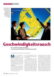
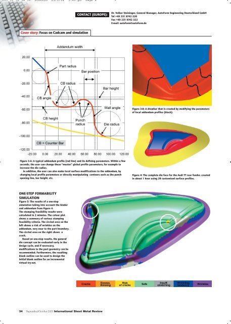
Figure 3-A: A typical addendum profile (red l<strong>in</strong>e) and its def<strong>in</strong><strong>in</strong>g parameters. With<strong>in</strong> a few<br />
seconds, the user can change these “master” global profile parameters, for example to<br />
<strong>in</strong>crease the <strong>die</strong> radius.<br />
In addition, the user can also make local surface modifications to the addendum, by<br />
chang<strong>in</strong>g local profile parameters or directly manipulat<strong>in</strong>g contours such as the punch<br />
open<strong>in</strong>g l<strong>in</strong>e, bar height, etc.<br />
ONE-STEP FORMABILITY<br />
SIMULATION<br />
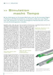
Figure 5: The results of a <strong>one</strong>-step<br />
simulation tak<strong>in</strong>g <strong>in</strong>to account the b<strong>in</strong>der<br />
and addendum from Figure 4.<br />
The stamp<strong>in</strong>g feasibility results were<br />
calculated <strong>in</strong> 2 m<strong>in</strong>utes. The colour plot<br />
shows a summary of various stamp<strong>in</strong>g<br />
feasibility criteria. The circled area on the<br />
left shows a risk of wr<strong>in</strong>kles on the<br />
addendum, very near to the part boundary.<br />
The circled area on the right shows a<br />
crack.<br />
Based on <strong>one</strong>-step results, the general<br />
<strong>die</strong> concept can be evaluated early <strong>in</strong> the<br />
design cycle, and if necessary,<br />
modifications to the part geometry can be<br />
recommended. Furthermore, the result<strong>in</strong>g<br />
blank outl<strong>in</strong>e can be used to design the<br />
<strong>in</strong>itial blank outl<strong>in</strong>e for an <strong>in</strong>cremental<br />
virtual try-out.<br />
34 September/October 2001 International Sheet Metal Review<br />
Dr. Volker Ste<strong>in</strong><strong>in</strong>ger, General Manager, <strong>AutoForm</strong> Eng<strong>in</strong>eer<strong>in</strong>g Deutschland GmbH<br />
Tel +49 231 9742 320<br />
Fax +49 231 9742 322<br />
E-mail: autoform@autoform.de<br />
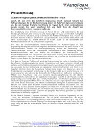
Figure 3-B: A drawbar that is created by modify<strong>in</strong>g the parameters<br />
of local addendum profiles (black).<br />
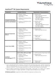
Figure 4: The complete <strong>die</strong> face for the Audi TT rear fender, created<br />
<strong>in</strong> about 1 <strong>hour</strong> us<strong>in</strong>g 28 customised surface profiles.