Parametric die faces in one hour - AutoForm Engineering
Parametric die faces in one hour - AutoForm Engineering
Parametric die faces in one hour - AutoForm Engineering

You also want an ePaper? Increase the reach of your titles
YUMPU automatically turns print PDFs into web optimized ePapers that Google loves.
29 30 32 34 36 utoform 21/1/04 3:39 pm Page 1<br />
The automotive <strong>in</strong>dustry<br />
shares a common goal to<br />
reduce new car development<br />
cycles from 48 - 60 months<br />
to only 24 months. To help<br />
achieve such a drastic reduction<br />
<strong>in</strong> “time-to-market”, companies<br />
have focused on cutt<strong>in</strong>g tool<strong>in</strong>g<br />
development time, which represents<br />
a large share of the total<br />
product development cycle.<br />
Draw-<strong>die</strong> development – the creation<br />
of b<strong>in</strong>der and addendum surface<br />
geometry for sheet-metal parts<br />
– has represented a particularly<br />
difficult challenge for automotive<br />
manufacturers and suppliers to<br />
reduce lead-time and tool<strong>in</strong>g costs.<br />
Over the past year, 20 automotive<br />
manufacturers and 20 lead<strong>in</strong>g<br />
tool<strong>in</strong>g suppliers <strong>in</strong> Europe, North<br />
America and Asia have all implemented<br />
a new software to address<br />
this problem (see Figure 1).<br />
TRADITIONAL BINDER AND<br />
ADDENDUM DESIGN PROBLEMS<br />
Once the product design department<br />
f<strong>in</strong>alises the design of a new<br />
sheet metal part, for example a<br />
deck-lid, fender, bracket or crossmember,<br />
it is released to the feasibility<br />
and tool<strong>in</strong>g departments<br />
who must then design an appropriate<br />
stamp<strong>in</strong>g <strong>die</strong> to fabricate<br />
the part.<br />
The traditional approach is for<br />
methods eng<strong>in</strong>eers and <strong>die</strong> designers<br />
to create or “build” the<br />
required b<strong>in</strong>der and addendum<br />
sur<strong>faces</strong> <strong>in</strong> a CAD system.<br />
However, this method has three<br />
disadvantages:<br />
1. Long lead time<br />
Design<strong>in</strong>g <strong>die</strong> <strong>faces</strong> <strong>in</strong> a conven-<br />
Cover story: Focus on Cadcam and simulation<br />
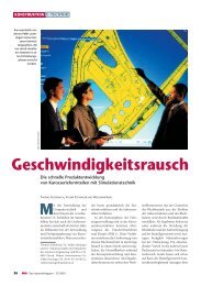
<strong>Parametric</strong> <strong>die</strong> <strong>faces</strong> <strong>in</strong> <strong>one</strong> <strong>hour</strong><br />
How 20 auto<br />
manufacturers and 20<br />
tool<strong>in</strong>g suppliers are<br />
reduc<strong>in</strong>g <strong>die</strong> design costs<br />
through automated<br />
software tools<br />
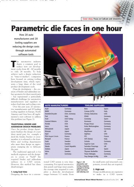
AUTO MANUFACTURERS TOOLING SUPPLIERS<br />
Audi<br />
BMW<br />
DaimlerChrysler<br />
Fiat<br />
Ford<br />
General Motors<br />
Honda<br />
Iveco<br />
Mitisubishi<br />
Nisssan<br />
Opel<br />
PSA Peugeot Citroën<br />
Renault<br />
Saab<br />
Scania<br />
Skoda<br />
Subaru<br />
Volvo<br />
VW<br />
Germany<br />
Germany<br />
USA, Germany<br />
Italy<br />
USA Turkey<br />
USA<br />
USA<br />
Italy<br />
Japan<br />
Japan<br />
Germany<br />
France<br />
France<br />
Sweden<br />
Sweden<br />
Czech Republic<br />
Japan<br />
Sweden<br />
Germany<br />
tional CAD system is very timeconsum<strong>in</strong>g.<br />
For typical automotive<br />
sk<strong>in</strong> panels and large <strong>in</strong>ner panels,<br />
the average time required to complete<br />
a draw-<strong>die</strong> development<br />
ranges between 1-2 weeks. Even<br />
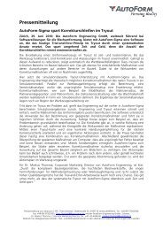
Figure 1: 40<br />
automotive and<br />
tool<strong>in</strong>g companies<br />
engaged <strong>in</strong> driv<strong>in</strong>g<br />
down lead times<br />
and reduc<strong>in</strong>g cost<br />
Batz<br />
Comau (UTS)<br />
Christy Industries<br />
EDAG<br />
Gestamp<br />
Karmann<br />
Krupp Drauz<br />
Kuka Werkzeugbau<br />
Laepple<br />
Mayflower<br />
Ogihara<br />
PCI<br />
SAT (Stola)<br />
Schuler<br />
Superior Cam<br />
Sw<strong>in</strong>don Press<strong>in</strong>gs<br />
Tecnisabadell<br />
Thyssen Nothelfer<br />
Tower Meleghy<br />
Troy Design & Mfg<br />
Spa<strong>in</strong><br />
Italy<br />
USA<br />
Germany<br />
Spa<strong>in</strong><br />
Germany<br />
Germany<br />
Germany<br />
Germany<br />
UK<br />
USA<br />
France<br />
Italy<br />
Germany<br />
USA<br />
UK<br />
Spa<strong>in</strong><br />
Germany<br />
Germany<br />
USA<br />
for small parts and structural comp<strong>one</strong>nts,<br />
several days are required.<br />
2. High cost<br />
Design modifications are expensive<br />
to make <strong>in</strong> a CAD system.<br />
International Sheet Metal Review September/October 2001 29<br />
Courtesy of DaimlerChrysler
29 30 32 34 36 utoform 21/1/04 3:39 pm Page 2<br />
Cover story: Focus on Cadcam and simulation<br />
Successful draw-<strong>die</strong> developments<br />
require the expertise of <strong>die</strong> designers<br />
and methods eng<strong>in</strong>eers with many<br />
years of practical experience and<br />
good CAD skills. Almost always,<br />
they make several iterations of design<br />
modifications before f<strong>in</strong>alis<strong>in</strong>g a good<br />
stamp<strong>in</strong>g <strong>die</strong> (e.g. chang<strong>in</strong>g radii,<br />
adjust<strong>in</strong>g drawbars). However, mak<strong>in</strong>g<br />
such design modifications <strong>in</strong> a<br />
general purpose CAD system is cumbersome<br />
and slow. Mistakes, modifications,<br />
and especially the design of<br />
different “what-if” concepts for the<br />
b<strong>in</strong>der and addendum, are costly.<br />
Furthermore, when time runs out<br />
due to production deadl<strong>in</strong>es, companies<br />
are forced to carry out tool<strong>in</strong>g<br />
try-outs <strong>in</strong> the press, which is even<br />
more costly.<br />
3. Low throughput<br />
With a manual, CAD-based<br />
approach, the <strong>die</strong> designer must wait<br />
until the <strong>die</strong> sur<strong>faces</strong> are completed –<br />
several days or weeks – before carry<strong>in</strong>g<br />
out virtual try-out simulations to<br />
check his designs for cracks, wr<strong>in</strong>kles<br />
and other stamp<strong>in</strong>g criteria. It is far<br />
more productive and cost-effective if<br />
the <strong>die</strong> designer immediately tries<br />
out his <strong>die</strong> concepts, discards unfeasible<br />
designs early on, and concentrates<br />
on further develop<strong>in</strong>g only his<br />
best design(s).<br />
As a result of these drawbacks, several<br />
automotive companies participated<br />
<strong>in</strong> a program to develop a faster,<br />
more efficient and less costly method<br />
for <strong>die</strong> face design.<br />
PARAMETRIC AND FULLY<br />
INTEGRATED SOFTWARE<br />
<strong>AutoForm</strong>-DieDesigner software is<br />
the result of a development effort<br />
led by <strong>AutoForm</strong> Eng<strong>in</strong>eer<strong>in</strong>g<br />
GmbH (developers of sheet metal<br />
form<strong>in</strong>g software) <strong>in</strong> cooperation<br />
with tool<strong>in</strong>g departments at BMW<br />
and Audi, and with technical feedback<br />
from DaimlerChrysler and<br />
General Motors.<br />
The software reduces tool<strong>in</strong>g<br />
development time through rapid<br />
parametric design of <strong>die</strong> <strong>faces</strong>, and<br />
their immediate verification and<br />
optimisation with <strong>in</strong>tegrated stamp<strong>in</strong>g<br />
simulation modules.<br />
It is specialised for generat<strong>in</strong>g<br />
b<strong>in</strong>der and addendum sur<strong>faces</strong>, and<br />
AUTHORS:<br />
30 September/October 2001 International Sheet Metal Review<br />
Dr. Volker Ste<strong>in</strong><strong>in</strong>ger and<br />
Dr. Vallury Prabhakar<br />
The software reduces tool<strong>in</strong>g development<br />
time through rapid parametric design of<br />
<strong>die</strong> <strong>faces</strong>, and their immediate verification<br />
and optimisation with <strong>in</strong>tegrated stamp<strong>in</strong>g<br />
simulation modules.<br />
for evaluat<strong>in</strong>g the feasibility of draw<strong>die</strong><br />
developments and prototype<br />
tools. Its three most important <strong>in</strong>novations<br />
are:<br />
• Fully parametric features,<br />
• Complete <strong>in</strong>tegration with virtual<br />
try-out software modules, and<br />
• An automatic optimiser.<br />
The software’s parametric<br />
approach is based on analytical eng<strong>in</strong>eer<strong>in</strong>g<br />
pr<strong>in</strong>ciples. It also conforms to<br />
the <strong>die</strong> eng<strong>in</strong>eer<strong>in</strong>g practice of us<strong>in</strong>g<br />
surface profiles (arcs and angles) to<br />
design <strong>die</strong> <strong>faces</strong> and is compatible<br />
with various CAD data formats.<br />
DIE FACES COMPLETE DRAW-DIE<br />
DEVELOPMENTS IN ONE HOUR<br />
Us<strong>in</strong>g the software, it takes about <strong>one</strong><br />
<strong>hour</strong> to design the complete <strong>die</strong> <strong>faces</strong><br />
start<strong>in</strong>g from only the CAD surface<br />
data of the part. This <strong>in</strong>cludes the follow<strong>in</strong>g<br />
steps:<br />
• Determ<strong>in</strong>ation of tip-angle<br />
• Fillet<strong>in</strong>g of sharp edges<br />
(variable radii)<br />
• Fill<strong>in</strong>g of holes<br />
• Part modifications (morph<strong>in</strong>g)<br />
• Design of the fill surface between<br />
double-attached parts<br />
• Over-crown<strong>in</strong>g<br />
• B<strong>in</strong>der design<br />
• Design of outer (and if required,<br />
<strong>in</strong>ner) addendum<br />
• Unfold<strong>in</strong>g of flanges<br />
• Generation of the tools<br />
As all the generated <strong>die</strong> sur<strong>faces</strong><br />
are parametric, subsequent modifications<br />
(<strong>die</strong> eng<strong>in</strong>eer<strong>in</strong>g changes) are<br />
implemented <strong>in</strong> seconds. These <strong>die</strong><br />
sur<strong>faces</strong> and simulation results can<br />
easily be exported us<strong>in</strong>g IGES,<br />
VDAFS or mesh formats to other<br />
software applications, e.g. patternmak<strong>in</strong>g,<br />
structural/crash analysis<br />
modules, etc.<br />
Courtesy of BMW
29 30 32 34 36 utoform 21/1/04 3:39 pm Page 3<br />
Cover story: Focus on Cadcam and simulation<br />
EASY PART DESIGN<br />
MODIFICATIONS<br />
As almost all part designs are subject<br />
to revisions and improvements<br />
even after they have been<br />
“officially released” to the <strong>die</strong><br />
design department, the software<br />
allows for this.<br />
After the parameterised b<strong>in</strong>der<br />
and addendum have been created<br />
for a specific part, <strong>one</strong> can then<br />
replace that part with another (similar)<br />
part designwith a modified<br />
design and the software will automatically<br />
adjust the b<strong>in</strong>der and<br />
addendum accord<strong>in</strong>gly.<br />
This is an important time-sav<strong>in</strong>g<br />
feature as it allows the orig<strong>in</strong>al<br />
addendum and b<strong>in</strong>der geometry<br />
that is created, to be re-used for<br />
future design revisions of the part.<br />
In addition, automatic fillet<strong>in</strong>g<br />
and the ability to vary fillet radii<br />
on the part geometry, saves considerable<br />
time and allows virtual<br />
try-outs to be carried out earlier <strong>in</strong><br />
the product and tool<strong>in</strong>g development<br />
cycles.<br />
.<br />
DIRECT PARAMETRIC LINK TO<br />
STAMPING SIMULATION<br />
SOFTWARE<br />
As a result of the software’s <strong>in</strong>tegrated<br />
system approach and full<br />
parametric l<strong>in</strong>k<strong>in</strong>g, all <strong>die</strong> face<br />
designs can be immediately evaluated<br />
with <strong>one</strong>-step or <strong>in</strong>cremental<br />
simulation modules.<br />
One-step simulation results are<br />
considerably more reliable when<br />
based on the complete <strong>die</strong> face – as<br />
generated by the software – rather<br />
than on the part only. An added<br />
benefit is that these ref<strong>in</strong>ed results<br />
are made possible earlier <strong>in</strong> the<br />
design cycle. They are available<br />
with<strong>in</strong> a few m<strong>in</strong>utes and <strong>in</strong>clude<br />
the required blank outl<strong>in</strong>e and various<br />
stamp<strong>in</strong>g feasibility criteria<br />
(see Figure 5).<br />
The <strong>in</strong>cremental module is used<br />
for high accuracy and virtual try-outs<br />
of the complete stamp<strong>in</strong>g process.<br />
Results <strong>in</strong>clude predictions of wr<strong>in</strong>kles,<br />
cracks, skid and impact l<strong>in</strong>es,<br />
surface quality, etc. Incremental tryout<br />
results are typically available<br />
with<strong>in</strong> 1 <strong>hour</strong> to 3 <strong>hour</strong>s, depend<strong>in</strong>g<br />
on the size and complexity of the<br />
part and the desired accuracy.<br />
32 September/October 2001 International Sheet Metal Review<br />
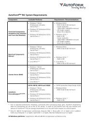
DESIGN OF PARAMETRIC DIE FACES FOR AUDI TT<br />
Figure 2-A: The part geometry (CAD sur<strong>faces</strong>) of an Audi TT rear fender.<br />
Figure 2-B: The <strong>in</strong>itial b<strong>in</strong>der surface (yellow) automatically created <strong>in</strong> a few seconds, us<strong>in</strong>g<br />
only the CAD surface data <strong>in</strong> Figure 2-A as <strong>in</strong>put. The user can then modify the b<strong>in</strong>der<br />
geometry with surface profiles.<br />
Figure 2-C: View of the automatically generated addendum surface (red), based on default<br />
profiles.<br />
Additional try-outs can be<br />
launched at once because of parametric<br />
l<strong>in</strong>k<strong>in</strong>g. For example,<br />
based on the <strong>in</strong>itial results, the<br />
user can make modifications to<br />
the addendum geometry, and the<br />
various tool geometries required<br />
for the next simulations are automatically<br />
updated. Similarly, if<br />
the user modifies the punch open<strong>in</strong>g<br />
l<strong>in</strong>e, drawbead positions are<br />
automatically adjusted.<br />
Courtesy of Audi
29 30 32 34 36 utoform 21/1/04 3:40 pm Page 4<br />
Cover story: Focus on Cadcam and simulation<br />
CONTACT (EUROPE):<br />
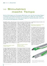
Figure 3-A: A typical addendum profile (red l<strong>in</strong>e) and its def<strong>in</strong><strong>in</strong>g parameters. With<strong>in</strong> a few<br />
seconds, the user can change these “master” global profile parameters, for example to<br />
<strong>in</strong>crease the <strong>die</strong> radius.<br />
In addition, the user can also make local surface modifications to the addendum, by<br />
chang<strong>in</strong>g local profile parameters or directly manipulat<strong>in</strong>g contours such as the punch<br />
open<strong>in</strong>g l<strong>in</strong>e, bar height, etc.<br />
ONE-STEP FORMABILITY<br />
SIMULATION<br />
Figure 5: The results of a <strong>one</strong>-step<br />
simulation tak<strong>in</strong>g <strong>in</strong>to account the b<strong>in</strong>der<br />
and addendum from Figure 4.<br />
The stamp<strong>in</strong>g feasibility results were<br />
calculated <strong>in</strong> 2 m<strong>in</strong>utes. The colour plot<br />
shows a summary of various stamp<strong>in</strong>g<br />
feasibility criteria. The circled area on the<br />
left shows a risk of wr<strong>in</strong>kles on the<br />
addendum, very near to the part boundary.<br />
The circled area on the right shows a<br />
crack.<br />
Based on <strong>one</strong>-step results, the general<br />
<strong>die</strong> concept can be evaluated early <strong>in</strong> the<br />
design cycle, and if necessary,<br />
modifications to the part geometry can be<br />
recommended. Furthermore, the result<strong>in</strong>g<br />
blank outl<strong>in</strong>e can be used to design the<br />
<strong>in</strong>itial blank outl<strong>in</strong>e for an <strong>in</strong>cremental<br />
virtual try-out.<br />
34 September/October 2001 International Sheet Metal Review<br />
Dr. Volker Ste<strong>in</strong><strong>in</strong>ger, General Manager, <strong>AutoForm</strong> Eng<strong>in</strong>eer<strong>in</strong>g Deutschland GmbH<br />
Tel +49 231 9742 320<br />
Fax +49 231 9742 322<br />
E-mail: autoform@autoform.de<br />
Figure 3-B: A drawbar that is created by modify<strong>in</strong>g the parameters<br />
of local addendum profiles (black).<br />
Figure 4: The complete <strong>die</strong> face for the Audi TT rear fender, created<br />
<strong>in</strong> about 1 <strong>hour</strong> us<strong>in</strong>g 28 customised surface profiles.
29 30 32 34 36 utoform 21/1/04 3:40 pm Page 5<br />
Cover story: Focus on Cadcam and simulation<br />
AUTOMATIC OPTIMISATION OF<br />
TOOLING AND STAMPING<br />
PROCESS<br />
To further improve the <strong>die</strong> face<br />
designs, the software <strong>in</strong>cludes an<br />
<strong>in</strong>tegrated optimiser module.<br />
The user first specifies the allowable<br />
ranges for tool geometry and<br />
stamp<strong>in</strong>g parameters. The optimiser<br />
then automatically determ<strong>in</strong>es<br />
the “best” design with<strong>in</strong><br />
these ranges through multiple<br />
<strong>one</strong>-step or <strong>in</strong>cremental simulations,<br />
to achieve the target function:<br />
for example, elim<strong>in</strong>ation of<br />
cracks and wr<strong>in</strong>kles, uniform surface<br />
stretch<strong>in</strong>g, no excessive<br />
th<strong>in</strong>n<strong>in</strong>g. Tool geometry parameters<br />
<strong>in</strong>clude part, <strong>die</strong> and drawbar<br />
radii, drawbar height, wall<br />
angles, over-crown, etc.<br />
Stamp<strong>in</strong>g parameters <strong>in</strong>clude<br />
b<strong>in</strong>der forces, drawbead strength,<br />
blank outl<strong>in</strong>e, etc.<br />
Benefits<br />
With<strong>in</strong> the first year of us<strong>in</strong>g<br />
<strong>AutoForm</strong>-DieDesigner, auto<br />
manufacturers and tool<strong>in</strong>g suppliers<br />
have already reported the<br />
follow<strong>in</strong>g sav<strong>in</strong>gs:<br />
• Reduced b<strong>in</strong>der development<br />
time by 60%<br />
• Reduction by a factor of 4-5,<br />
<strong>in</strong> the time from CAD part<br />
design until completed virtual<br />
try-outs<br />
• Reduction of <strong>die</strong> face develop<br />
ment time from <strong>one</strong> week<br />
down to <strong>one</strong> day<br />
• Almost 50% reduction <strong>in</strong><br />
actual <strong>die</strong> try-out time and<br />
tool<strong>in</strong>g costs<br />
• Two week reduction of tool<strong>in</strong>g<br />
development time, by us<strong>in</strong>g<br />
the generated <strong>die</strong> <strong>faces</strong> to<br />
order cast<strong>in</strong>gs for the <strong>die</strong>s.<br />
Although it is too early to<br />
quantify all benefits, companies<br />
also expect improved part<br />
quality and stamp<strong>in</strong>g reliability<br />
due to the optimisation of<br />
their designs. ISMR<br />
CONTACT (USA):<br />
36 September/October 2001 International Sheet Metal Review<br />
Dr. Vallury Prabhakar, General Manager, <strong>AutoForm</strong> Eng<strong>in</strong>eer<strong>in</strong>g USA Inc.<br />
Tel: +1 888 428-8636<br />
Fax: +1 888 528-8636<br />
E-mail: autoformUSA@autoformUSA.com<br />
www.autoform.de<br />
INCREMENTAL STAMPING TRY-OUT SIMULATION<br />
Figure 6: The results of an accurate <strong>in</strong>cremental try-out simulation of the complete stamp<strong>in</strong>g process, us<strong>in</strong>g the <strong>die</strong><br />
<strong>faces</strong> from Figure 4.<br />
The colour plot shows the predicted thickness distribution; excessive th<strong>in</strong>n<strong>in</strong>g z<strong>one</strong>s are <strong>in</strong> red and yellow (two<br />
circled areas on the right). The simulation also shows wr<strong>in</strong>kles <strong>in</strong> the circled area on the left. These try-out results<br />
were obta<strong>in</strong>ed <strong>in</strong> about 50 m<strong>in</strong>utes.<br />
The <strong>die</strong> designer can then make modifications to his orig<strong>in</strong>al <strong>die</strong> concept to smooth out the wr<strong>in</strong>kles and<br />
elim<strong>in</strong>ate the cracks, for example by chang<strong>in</strong>g drawbar and wall heights, radii, etc. Furthermore, results such as<br />
wr<strong>in</strong>kl<strong>in</strong>g, splitt<strong>in</strong>g, skid mark progression, etc. can be visualised at each step of the draw<strong>in</strong>g process.<br />
OPTIMISATION<br />
Figure 7: The results of optimisation of the <strong>in</strong>itial <strong>in</strong>cremental try-out <strong>in</strong> Figure 6.<br />
The two crack z<strong>one</strong>s were elim<strong>in</strong>ated and the wr<strong>in</strong>kl<strong>in</strong>g z<strong>one</strong> was m<strong>in</strong>imised and moved away from the part<br />
boundary.<br />
Automatic optimisation can help the <strong>die</strong> designer to f<strong>in</strong>d the best parameters for his design. It can also help the<br />
process eng<strong>in</strong>eer to determ<strong>in</strong>e the best stamp<strong>in</strong>g conditions.