Latent fingerprint detection using a scanning Kelvin ... - Library
Latent fingerprint detection using a scanning Kelvin ... - Library
Latent fingerprint detection using a scanning Kelvin ... - Library

Create successful ePaper yourself
Turn your PDF publications into a flip-book with our unique Google optimized e-Paper software.
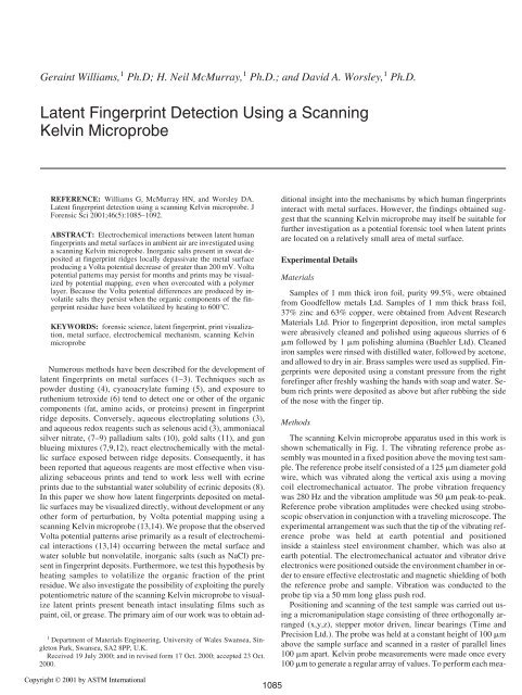
Geraint Williams, 1 Ph.D; H. Neil McMurray, 1 Ph.D.; and David A. Worsley, 1 Ph.D.<br />
<strong>Latent</strong> Fingerprint Detection Using a Scanning<br />
<strong>Kelvin</strong> Microprobe<br />
REFERENCE: Williams G, McMurray HN, and Worsley DA.<br />
<strong>Latent</strong> <strong>fingerprint</strong> <strong>detection</strong> <strong>using</strong> a <strong>scanning</strong> <strong>Kelvin</strong> microprobe. J<br />
Forensic Sci 2001;46(5):1085–1092.<br />
ABSTRACT: Electrochemical interactions between latent human<br />
<strong>fingerprint</strong>s and metal surfaces in ambient air are investigated <strong>using</strong><br />
a <strong>scanning</strong> <strong>Kelvin</strong> microprobe. Inorganic salts present in sweat deposited<br />
at <strong>fingerprint</strong> ridges locally depassivate the metal surface<br />
producing a Volta potential decrease of greater than 200 mV. Volta<br />
potential patterns may persist for months and prints may be visualized<br />
by potential mapping, even when overcoated with a polymer<br />
layer. Because the Volta potential differences are produced by involatile<br />
salts they persist when the organic components of the <strong>fingerprint</strong><br />
residue have been volatilized by heating to 600°C.<br />
KEYWORDS: forensic science, latent <strong>fingerprint</strong>, print visualization,<br />
metal surface, electrochemical mechanism, <strong>scanning</strong> <strong>Kelvin</strong><br />
microprobe<br />
Numerous methods have been described for the development of<br />
latent <strong>fingerprint</strong>s on metal surfaces (1–3). Techniques such as<br />
powder dusting (4), cyanoacrylate fuming (5), and exposure to<br />
ruthenium tetroxide (6) tend to detect one or other of the organic<br />
components (fat, amino acids, or proteins) present in <strong>fingerprint</strong><br />
ridge deposits. Conversely, aqueous electroplating solutions (3),<br />
and aqueous redox reagents such as selenous acid (3), ammoniacal<br />
silver nitrate, (7–9) palladium salts (10), gold salts (11), and gun<br />
blueing mixtures (7,9,12), react electrochemically with the metallic<br />
surface exposed between ridge deposits. Consequently, it has<br />
been reported that aqueous reagents are most effective when visualizing<br />
sebaceous prints and tend to work less well with ecrine<br />
prints due to the substantial water solubility of ecrinic deposits (8).<br />
In this paper we show how latent <strong>fingerprint</strong>s deposited on metallic<br />
surfaces may be visualized directly, without development or any<br />
other form of perturbation, by Volta potential mapping <strong>using</strong> a<br />
<strong>scanning</strong> <strong>Kelvin</strong> microprobe (13,14). We propose that the observed<br />
Volta potential patterns arise primarily as a result of electrochemical<br />
interactions (13,14) occurring between the metal surface and<br />
water soluble but nonvolatile, inorganic salts (such as NaCl) present<br />
in <strong>fingerprint</strong> deposits. Furthermore, we test this hypothesis by<br />
heating samples to volatilize the organic fraction of the print<br />
residue. We also investigate the possibility of exploiting the purely<br />
potentiometric nature of the <strong>scanning</strong> <strong>Kelvin</strong> microprobe to visualize<br />
latent prints present beneath intact insulating films such as<br />
paint, oil, or grease. The primary aim of our work was to obtain ad-<br />
1 Department of Materials Engineering, University of Wales Swansea, Singleton<br />
Park, Swansea, SA2 8PP, U.K.<br />
Received 19 July 2000; and in revised form 17 Oct. 2000; accepted 23 Oct.<br />
2000.<br />
Copyright © 2001 by ASTM International<br />
1085<br />
ditional insight into the mechanisms by which human <strong>fingerprint</strong>s<br />
interact with metal surfaces. However, the findings obtained suggest<br />
that the <strong>scanning</strong> <strong>Kelvin</strong> microprobe may itself be suitable for<br />
further investigation as a potential forensic tool when latent prints<br />
are located on a relatively small area of metal surface.<br />
Experimental Details<br />
Materials<br />
Samples of 1 mm thick iron foil, purity 99.5%, were obtained<br />
from Goodfellow metals Ltd. Samples of 1 mm thick brass foil,<br />
37% zinc and 63% copper, were obtained from Advent Research<br />
Materials Ltd. Prior to <strong>fingerprint</strong> deposition, iron metal samples<br />
were abrasively cleaned and polished <strong>using</strong> aqueous slurries of 6<br />
�m followed by 1 �m polishing alumina (Buehler Ltd). Cleaned<br />
iron samples were rinsed with distilled water, followed by acetone,<br />
and allowed to dry in air. Brass samples were used as supplied. Fingerprints<br />
were deposited <strong>using</strong> a constant pressure from the right<br />
forefinger after freshly washing the hands with soap and water. Sebum<br />
rich prints were deposited as above but after rubbing the side<br />
of the nose with the finger tip.<br />
Methods<br />
The <strong>scanning</strong> <strong>Kelvin</strong> microprobe apparatus used in this work is<br />
shown schematically in Fig. 1. The vibrating reference probe assembly<br />
was mounted in a fixed position above the moving test sample.<br />
The reference probe itself consisted of a 125 �m diameter gold<br />
wire, which was vibrated along the vertical axis <strong>using</strong> a moving<br />
coil electromechanical actuator. The probe vibration frequency<br />
was 280 Hz and the vibration amplitude was 50 �m peak-to-peak.<br />
Reference probe vibration amplitudes were checked <strong>using</strong> stroboscopic<br />
observation in conjunction with a traveling microscope. The<br />
experimental arrangement was such that the tip of the vibrating reference<br />
probe was held at earth potential and positioned<br />
inside a stainless steel environment chamber, which was also at<br />
earth potential. The electromechanical actuator and vibrator drive<br />
electronics were positioned outside the environment chamber in order<br />
to ensure effective electrostatic and magnetic shielding of both<br />
the reference probe and sample. Vibration was conducted to the<br />
probe tip via a 50 mm long glass push rod.<br />
Positioning and <strong>scanning</strong> of the test sample was carried out <strong>using</strong><br />
a micromanipulation stage consisting of three orthogonally arranged<br />
(x,y,z), stepper motor driven, linear bearings (Time and<br />
Precision Ltd.). The probe was held at a constant height of 100 �m<br />
above the sample surface and scanned in a raster of parallel lines<br />
100 �m apart. <strong>Kelvin</strong> probe measurements were made once every<br />
100 �m to generate a regular array of values. To perform each mea-
1086 JOURNAL OF FORENSIC SCIENCES<br />
surement the ac current, i(t), generated in the external circuit connecting<br />
the sample and vibrating probe (see following section), was<br />
amplified and converted into an ac voltage signal, v(t), <strong>using</strong> a dc<br />
biased transimpedance amplifier circuit. The v(t) signal was detected<br />
<strong>using</strong> a lock-in amplifier (Perkin Elmer model 7260). The dc<br />
output of the lock-in amplifier, vdc, was transmitted to a feedback<br />
system based on an integrator circuit which controlled the dc bias,<br />
E, applied to the sample via the transconductance amplifier so as to<br />
automatically null i(t). The magnitude of the dc bias (equivalent to<br />
�Ekp as defined in the following section) applied via the integrator,<br />
was digitized and logged. Probe <strong>scanning</strong> and data logging were all<br />
carried out automatically under microcomputer control. All scans<br />
were performed in ambient air (nominal temperature 22°C, R.H<br />
45%).<br />
Results and Discussion<br />
FIG. 1—Schematic representation of the major components of the <strong>scanning</strong> <strong>Kelvin</strong> microprobe apparatus.<br />
When the electrical potential of a metallic body is referred to, it<br />
is usually the Galvani, or inner, potential determined by the Fermi<br />
level of electrons within that body which is meant. At distances<br />
�10 �m from the metal surface, potential falls away with increasing<br />
distance as determined by the laws of electrostatics. However,<br />
between approximately 0.1 �m and 10 �m from the metal surface<br />
there exists a region where potential is approximately independent<br />
of distance; this is known as the Volta, or outer, potential of the<br />
metal. In vacuum, the Volta potential reflects the extension of electronic<br />
wavefunctions beyond the surface, a tendency related to the<br />
work function of the metal. If the metal is in contact with a solution<br />
of electrolyte, adsorbtion of ions in the electrical double layer also<br />
affects the Volta potential, which corresponds approximately to the<br />
potential at the inner Helmholtz plane (15).<br />
As the name suggests, the <strong>scanning</strong> <strong>Kelvin</strong> probe (SKP) technique<br />
is based upon the vibrating capacitor method pioneered by<br />
Lord <strong>Kelvin</strong> (16), for the measurement of metallic work functions.<br />
The theory underlying <strong>Kelvin</strong> probe measurements has been described<br />
in detail elsewhere (13,14) but may be summarized as follows.<br />
The vibrating probe tip and sample surface form the two<br />
plates of a parallel plate capacitor, while the space between them,<br />
typically air or a combination of air-gap and nonconducting material,<br />
constitutes the dielectric. If a Volta potential difference (�V)<br />
exists between the probe and the sample surface, the periodic<br />
change in capacitance caused by probe vibration, generates an al-<br />
FIG. 2—Schematic diagram illustrating the principle of operation of the<br />
<strong>Kelvin</strong> probe for measuring surface Volta potential differences. Volta potential<br />
difference, �V; <strong>Kelvin</strong> probe current signal, i(t); externally applied<br />
dc bias voltage, E.<br />
ternating current in the external circuit shown in Fig. 2. The timedependent<br />
value, i(t), of this current is given by Eq. 1:<br />
i(t) � �� 0 A �V{d1� cos(�t)/(d0 � d1 sin(�t))} (1)<br />
where � is the permitivity of free space, � 0 is the dielectric constant<br />
of the inter-electrode medium, A is the effective probe tip area, d1<br />
is the probe vibration amplitude, d0 the mean probe-surface distance,<br />
� the angular frequency of probe vibration, and t is time. The<br />
<strong>Kelvin</strong> probe measurement is made by current nulling, i.e., a d.c.<br />
bias voltage (E in Fig. 2) is adjusted until �V, and hence the magnitude<br />
of i(t), is zero. Under null-current conditions the experimentally<br />
measured parameter E(i�0) is equal and opposite to the value<br />
of �V which would exist if the Galvani potentials of the probe and<br />
sample were identical, i.e., if E were zero. It is customary to refer<br />
to the quantity �E(i�0) as the <strong>Kelvin</strong> probe potential (Ekp). We have<br />
used a gold vibrating probe, so that in our work Ekp is equivalent to<br />
the Volta potential of the sample surface relative to that of gold at<br />
the same Galvani potential.<br />
When measurements are performed on pristine surfaces under<br />
vacuum, Ekp is determined only by the difference in work functions
etween the probe and test sample surfaces. Scanning <strong>Kelvin</strong> probe<br />
microscopes, having lateral resolutions of 100 nm or better, have<br />
recently been developed for the study of metal structures and<br />
dopant profiles on semiconductor surfaces (17–19) under high<br />
vacuum. In contrast to these systems, which are typically used to<br />
image areas of a few microns square, the SKP apparatus described<br />
here to image <strong>fingerprint</strong>s scans much larger areas (up to 5 cm by<br />
5 cm) and has a lateral resolution of ~125 �m. Our apparatus is<br />
based on instrumentation developed to study metallic corrosion occurring<br />
under thin films of electrolyte (13,14) and electrolyte<br />
droplets (20).<br />
Any metal surface exposed to moist air will acquire a so-called<br />
humidity layer of adsorbed water molecules, the thickness of which<br />
increases with relative humidity (13,21). If any environmentally<br />
derived electrolyte (ionic salts) are associated with this humidity<br />
layer, Ekp values will tend to deviate from those determined purely<br />
on the basis of work function differences as a result of ionic adsorbtion<br />
and electrochemical redox reactions associated with<br />
corrosion processes occurring at the sample surface. The relationship<br />
between Ekp and redox activity has been discussed in detail<br />
elsewhere (13). However, for our purposes the most important<br />
finding is that Ekp measured through an adsorbed electrolyte film<br />
directly reflects the electrochemical open circuit potential, or free<br />
corrosion potential (Ecorr), of the metal surface in relation to that<br />
electrolyte. So that,<br />
Ekp � Ecorr � C (2)<br />
where C is a constant determined by the probe material and the potential<br />
drop at the electrolyte-air interface (13). For any freely corroding<br />
metal, M, the value of Ecorr is determined by the relative facility<br />
of the anodic oxidation process (Eq 3) and the cathodic<br />
WILLIAMS ET AL. • LATENT FINGERPRINT DETECTION 1087<br />
reduction process, which under aerobic conditions is typically oxygen<br />
reduction (Eq 4).<br />
M D M n� � ne �<br />
O2 � 2H2O � 4e � D 4OH �<br />
It is well known that when a metal surface is covered with an insoluble<br />
(passive) oxide film, reaction (3) is inhibited and the metal<br />
will exhibit more positive Ecorr values than when the same metal is<br />
actively corroding to a soluble oxidation product (22), as shown<br />
schematically in Fig. 3. Thus, when a single metal surface is<br />
covered by a thin film of adsorbed electrolyte, regions of that metal<br />
surface covered with a passive oxide film will typically exhibit<br />
significantly higher Ekp than those where the passive film has broken<br />
down.<br />
Many metals spontaneously develop passive surface films,<br />
which may range from nanometers to several microns in thickness,<br />
when exposed to moist air. However, so-called aggressive ions,<br />
such as chloride (Cl � ), tend to break down passive films and activate<br />
metal surfaces through the formation of soluble metal choride<br />
complexes (22). Consequently, the chloride rich inorganic salts<br />
present in the aqueous component of <strong>fingerprint</strong> secretions will<br />
tend to cause local depassivation of a metal surface in areas where<br />
secretions are deposited. Thus, when a <strong>Kelvin</strong> microprobe is<br />
scanned over a latent <strong>fingerprint</strong>, it is to be expected that ridges<br />
will be disclosed as regions of lower Ekp against the background of<br />
passive metal.<br />
That this is actually the case is clearly illustrated in Fig. 4a,<br />
where a latent <strong>fingerprint</strong>, freshly deposited on a polished iron surface,<br />
has been visualized by mapping Ekp at a resolution of 10 data<br />
points per mm along both x and y axes. The interpolated greyscale<br />
FIG. 3—Evans, potential (E)–log current modulus (i) diagram showing the effect of a passive-active transition on the free corrosion potential (Ecorr) of<br />
a metallic surface. Under free corrosion conditions the Ecorr corresponds to that potential where the anodic and cathodic currents are equal and opposite.<br />
(3)<br />
(4)
1088 JOURNAL OF FORENSIC SCIENCES<br />
FIG. 4—(a) The Ekp pattern produced by <strong>fingerprint</strong> deposited on an iron surface, as imaged by the Scanning <strong>Kelvin</strong> microprobe <strong>using</strong> a resolution of<br />
10 points per mm. (b) A photographic image of the same area taken under illumination at a 30° angle of incidence.<br />
image, produced from the matrix of Ekp values, has been generated<br />
<strong>using</strong> commercially available cartography software (Surfer,<br />
Golden Software). The ridge detail and characteristic right hand<br />
loop pattern of the sample <strong>fingerprint</strong> are clearly visible and exactly<br />
match the photographic image shown in Fig. 4b, which was<br />
obtained <strong>using</strong> glancing angle illumination. It can been seen from<br />
Fig. 4a that Ekp values in ridge regions may be up to 280 mV lower<br />
than the background. When samples were stored in ambient air<br />
this Ekp pattern was still clearly detectable one month after the <strong>fingerprint</strong><br />
was applied. Visual evidence of corrosion could be detected<br />
two to three weeks after initially depositing the <strong>fingerprint</strong>.<br />
Further tests have shown that <strong>fingerprint</strong>s deposited on a range of<br />
other metals, such as copper, aluminum, nickel and titanium and<br />
various alloys including brass, can also be efficiently visualized in<br />
this way.<br />
Since the <strong>Kelvin</strong> probe measurement is made under null-current<br />
conditions, Ekp is independent of the dielectric constant of the<br />
medium lying between the vibrating probe and sample surface.<br />
This property has been exploited in work <strong>using</strong> the SKP technique<br />
as a tool for investigating localized corrosion phenomena<br />
occurring beneath polymer coatings applied to metal substrates<br />
(23–25). It has been shown that electrochemically determined
Volta potential differences occurring over the metal surface can<br />
be mapped through a continuous polymer film. The technique<br />
should therefore be capable of detecting a latent <strong>fingerprint</strong> pattern<br />
under similar circumstances. The ability of the SKP to detect<br />
Volta potential distributions associated with <strong>fingerprint</strong> patterns<br />
overcoated with intact, insulating films was assessed by applying<br />
prints to iron substrates as above and then applying a range of<br />
polymer based coatings. The Ekp pattern shown in Fig. 5a was obtained<br />
after spray painting over a freshly deposited <strong>fingerprint</strong><br />
with a commercially available clear cellulosic lacquer (plasticoat),<br />
to give a film thickness of 20 �m. The line plot in Fig. 5b<br />
illustrates the variation of Ekp over a cross section of the <strong>fingerprint</strong><br />
pattern indicated by the dashed line in Fig. 5a. The sample<br />
WILLIAMS ET AL. • LATENT FINGERPRINT DETECTION 1089<br />
was stored in ambient air and the Ekp patterns in Fig. 5 were still<br />
clearly detectable one month after the substrate was overcoated.<br />
Other metal surfaces, including brass and copper, printed then<br />
overcoated with various pigmented and clear paint systems gave<br />
similar results, although application of coatings by brushing led to<br />
some smearing of the Volta potential pattern.<br />
If Volta potential differences are induced by inorganic salts, the<br />
SKP should allow print visualization in situations were <strong>fingerprint</strong>ed<br />
surfaces have been subjected to elevated temperatures,<br />
ca<strong>using</strong> volatilization of the organic component of the residue.<br />
We used a Gleeble electric welding simulation apparatus (26,27)<br />
to heat print-bearing 1 mm thick sheet brass samples through a<br />
preprogrammed temperature-time profile by passing large tran-<br />
FIG. 5—(a) The Ekp pattern produced by <strong>fingerprint</strong> deposited on an iron surface and overcoated <strong>using</strong> a spray applied cellulosic lacquer of 20 �m<br />
thickness. (b) A plot of Ekp versus distance along the broken line in 4(a) showing the characteristic Volta potential profile across the ridges of a latent print.
1090 JOURNAL OF FORENSIC SCIENCES<br />
FIG. 6—A comparison of Ekp patterns produced by a sebum rich <strong>fingerprint</strong> deposited on brass before (a) and after (b) being subjected to a rapid heating-cooling<br />
cycle employing a peak temperature of 600°C.<br />
sient dc currents controlled by temperature feedback. A heating<br />
rate of 200°C/s was used to attain target temperatures between<br />
400 and 600°C in room air. Samples were then allowed to cool<br />
naturally in air (exponential cooling with a half life of 3 s). Figure<br />
6 shows typical data, obtained from four day old sebum-rich<br />
prints visualized by SKP a) before and b) after heating to 600°C.<br />
It is evident from Fig. 6b that the <strong>fingerprint</strong> pattern is clearly visualized<br />
by Ekp mapping even after heating. Since the organic<br />
substances contained in the <strong>fingerprint</strong> are likely to have been<br />
vaporized at 600°C, the observation that patterns remain detectable<br />
is consistent with the hypothesis that the Volta potential<br />
changes detected by the <strong>Kelvin</strong> probe are produced by nonvolatile<br />
salt deposits.<br />
Although all the experiments outlined here were performed on<br />
planar samples, many real samples would obviously be nonplanar.<br />
Nonplanar samples can also be scanned provided the surface profile<br />
is known and used to control probe position. Surface profiling<br />
may be carried out <strong>using</strong> conventional mechanical or optical meth-
ods. However, recent work (28) has demonstrated that surface profiling<br />
is possible <strong>using</strong> the SKP itself by exploiting the fact that<br />
harmonic distortion in the <strong>Kelvin</strong> probe current [i(t) in Eq (1)] is<br />
dependent on probe to sample distance. Similarly, real samples<br />
may exhibit irregular surface textures and contamination by preexisting<br />
organic and/or inorganic films. Preliminary studies carried<br />
out by ourselves suggest that surface texture is not necessarily<br />
problematic provided the texture does not, of itself, produce a<br />
spreading (blurring) of the print deposit. However, the development<br />
of Volta potential differences may be suppressed by preexisting<br />
surface contamination if this prevents access of <strong>fingerprint</strong> salt<br />
deposits to the metal surface.<br />
Rubbing freshly deposited <strong>fingerprint</strong>s with a dry cloth may produce<br />
smearing of the resulting Volta potential variations or prevent<br />
their appearance altogether. However, once patterns of surface<br />
depassivation are well established (typically after several days)<br />
rubbing with a dry cloth has relatively little effect. Water or polar<br />
organic solvents tend to be more injurious and can destroy Volta<br />
potential patterns by redistributing salt deposits and inducing more<br />
general depassivation of the metal surface.<br />
Conclusions<br />
We have demonstrated that on metallic surfaces, such as iron or<br />
brass, the electrolytes present in latent <strong>fingerprint</strong> ridge<br />
deposits induce localized Volta potential variations that may be visualized<br />
directly <strong>using</strong> a <strong>scanning</strong> <strong>Kelvin</strong> microprobe (SKP). The<br />
observed Volta potential variations probably result from electrochemical<br />
depassivation of the metal surface by chloride ions and<br />
may persist for periods greater than one month when the metal is in<br />
contact with room air. They also persist when metal (brass) surfaces<br />
are heated to 600°C implying that the electrolytes concerned<br />
are primarily comprised of nonvolatile inorganic salts (such as<br />
NaCl). Once developed, Volta potential patterns are substantially<br />
unaffected by organic contamination superimposed by, for example,<br />
spray painting. However, contamination of the metal surface<br />
prior to print deposition may interfere with the development of<br />
Volta potential patterns if contaminants prevent print residue electrolytes<br />
from contacting the metal surface.<br />
Further work will obviously be necessary to determine whether<br />
the above findings are primarily of theoretical interest or whether<br />
the SKP is capable of being developed as a practical forensic tool.<br />
Nevertheless, the SKP possesses features which suggest that it is<br />
worthy of further investigation. The SKP is completely nonperturbing<br />
and does not require exposure of the print to radiation, vacuum<br />
or any other destructive agency, which could prove advantageous<br />
in situations where the <strong>fingerprint</strong> must be preserved for<br />
future extraction of genetic materials. Furthermore, because the<br />
Volta potential changes detected by SKP are primarily induced by<br />
nonvolatile inorganic salts it may be possible able to detect prints<br />
in instances where the organic components of the residue are<br />
scanty or have been lost as a result of exposure to high temperatures.<br />
Finally, because the SKP measurement is purely potentiometric<br />
it may be possible to visualize <strong>fingerprint</strong>s which have become<br />
overcoated or contaminated with insulating films such as<br />
paint, oil or grease.<br />
Regardless of whether the SKP itself proves to be of practical<br />
usefulness it is to be hoped that the findings presented here<br />
will contribute to the physico-chemical understanding of <strong>fingerprint</strong><br />
deposits and facilitate the rational design of reagents<br />
and techniques for forensic <strong>fingerprint</strong> visualization on metallic<br />
surfaces.<br />
WILLIAMS ET AL. • LATENT FINGERPRINT DETECTION 1091<br />
Acknowledgments<br />
The authors are indebted to Justin Searle and Bruce Carr for their<br />
assistance during instrument development. This work was funded<br />
by the UK Engineering and Physical Sciences Research Council<br />
(EPSRC).<br />
References<br />
1. Lee HC, Gaensslen RE, editors. Advances in <strong>fingerprint</strong> technology.<br />
New York; Elsevier, 1991.<br />
2. Hazen RJ. Significant advances in the science of <strong>fingerprint</strong>s. In: Davis<br />
GG, editor. Forensic Science. 2 nd . Washington DC: American Chemical<br />
Society, 1986;229–312.<br />
3. Bentsen RK, Brown JK, Dinsmore A, Harvey KK, Kee TG. Post firing<br />
visualisation of <strong>fingerprint</strong>s on spent cartridge cases. Science and Justice<br />
1996;36:3–8.<br />
4. James JD, Pounds CA, Wilshire B. Flake metal powders for revealing latent<br />
<strong>fingerprint</strong>s. J. Forensic Sci 1991;36:1368–74.<br />
5. Sampson WC. An inquiry into the methodology of preserving and developing<br />
latent prints on expended cartridge casings. J Forensic Ident<br />
1993;43:4–12.<br />
6. Mashiko K, German ER, Motojima, Colman CD. A new ruthenium<br />
tetroxide fuming procedure. J Forensic Ident 1991;41:429.<br />
7. Migron Y, Hocherman G, Springer E, Almog J, Mandler D. Visualization<br />
of sebaceous <strong>fingerprint</strong>s on fired cartridge cases: A laboratory<br />
study. J Forensic Sci 1998;43:543–8.<br />
8. Reed R. Development of latent prints on brass with silver nitrate. Ident<br />
News 1985;35(7):11.<br />
9. Schutz F, Bonfanti M, Champod C. La revelation des traces papillaires<br />
sur les douilles par les techniques de etching et de blueing et comparison<br />
avec la deposition multimetallique. Can Soc Forensic Sci J 2000;33:<br />
65–81.<br />
10. Migron Y, Mandler D. Development of latent <strong>fingerprint</strong>s on unfired<br />
cartridges by palladium deposition: A surface study. J Forensic Sci<br />
1997;42:986–92.<br />
11. Saunders GC, Cantu AA. Evaluation of several techniques for developing<br />
latent <strong>fingerprint</strong>s on unfired and fired cartridge cases. Proceedings,<br />
of the International Symposium on Fingerprint Detection and Identification;<br />
26–30 June 1995; Neurim. Israel: 155–60.<br />
12. Cantu AA, Leben DA, Ramotowski R, Kopera J, Simms JR. Use of acidified<br />
hydrogen peroxide to remove excess gun blue from gun bluetreated<br />
cartridge cases and to develop latent prints on untreated cartridge<br />
cases. J Forensic Sci 1998;43:294–8.<br />
13. Yee S, Oriani RA, Stratmann M. Application of a <strong>Kelvin</strong> microprobe to<br />
the corrosion of metals in humid atmospheres. J Electrochem Soc<br />
1991;138:55–60.<br />
14. McMurray HN, Worsley DA. Scanning electrochemical techniques for<br />
the study of localised metallic corrosion. In: Compton RG, Hancock G,<br />
editors. Research in chemical kinetics, Vol. 4. Oxford: Blackwell Science,<br />
1997:149–202.<br />
15. Brett CMA, Oliveira Brett AM. Electrochemistry: principles, methods<br />
and applications. Oxford; Oxford University Press, 1993.<br />
16. Thompson W, (Lord <strong>Kelvin</strong>). Contact electricity of metals. Philos Mag<br />
1898;42:82–101.<br />
17. Nonnenmacher M, O’Boyle MP, Wickramasinghe HK. <strong>Kelvin</strong> probe<br />
force microscopy. Appl Phys Lett 1988;58:2921–3.<br />
18. Henning AK, Hochwitz T, Slinkman J, Never J, Hoffmann S, Kaszuba<br />
P, et al. Two-dimensional surface dopant profiling in silicon <strong>using</strong> <strong>scanning</strong><br />
<strong>Kelvin</strong> probe microscopy. J Appl Phys 1995;77:1888–96.<br />
19. Chavez-Pirson A, Vatel O, Tanimoto M, Ando H, Iwamura H, Kanbe<br />
H. Nanometer-scale imaging of potential profiles in optically excited<br />
n-i-p-i heterostructure <strong>using</strong> <strong>Kelvin</strong> probe force microscopy. Appl Phys<br />
Lett 1995;67:3069–71.<br />
20. Chen C and Mansfeld F. Potential distribution in the Evans drop experiment.<br />
Corros Sci 1997;39:409–13.<br />
21. Leng A, Stratmann M. The inhibition of the atmospheric corrosion of<br />
iron by vapour phase inhibitors. Corrosion Sci 1993;34:1657–83.<br />
22. Trethewey KR, Chamberlain J. Corrosion for science and engineering.<br />
Harlow, England; Longman Scientific, 1995.<br />
23. Stratmann M, Streckel H, Feser R. A new technique able to measure<br />
directly the delamination of organic polymer films. Corrosion Sci<br />
1991;32:467–70.
1092 JOURNAL OF FORENSIC SCIENCES<br />
24. Furbeth W, Stratmann M. Investigation of the delamination of polymer<br />
films from galvanized steel with the <strong>scanning</strong> <strong>Kelvin</strong> probe. Fresenius J<br />
Anal Chem 1995;353:337–41.<br />
25. Leng A, Streckel H, Stratmann M. The delamination of polymeric coatings<br />
from steel. Part 1: Calibration of the <strong>Kelvin</strong>probe and basic delamination<br />
mechanism. Corrosion Sci 1999;41:547–78.<br />
26. Ferguson H. Metalworking process simulations save production<br />
headaches. Metal progress 1986;130:37–40.<br />
27. Ferguson H. The physical simulation of continuous steel processes. J<br />
Metals 1988;40:14–6.<br />
28. Cheran LE, Liess HD, Thompson M. Scanning <strong>Kelvin</strong> microprobe in the<br />
tandem analysis of surface topography and chemistry. Analyst 1999;<br />
124:961–70.<br />
Additional information and reprint requests:<br />
Dr. H.N. McMurray<br />
Department of Materials Engineering<br />
University of Wales Swansea<br />
Singleton Park<br />
Swansea SA2 8PP, U.K.