cst-studio-suite-2012-brochure-low.pdf (2.7
cst-studio-suite-2012-brochure-low.pdf (2.7
cst-studio-suite-2012-brochure-low.pdf (2.7

Create successful ePaper yourself
Turn your PDF publications into a flip-book with our unique Google optimized e-Paper software.
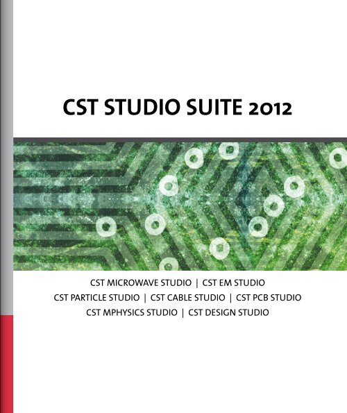
CST STUDIO SUITE <strong>2012</strong><br />
CST MICROWAVE STUDIO | CST EM STUDIO<br />
CST PARTICLE STUDIO | CST CABLE STUDIO | CST PCB STUDIO<br />
CST MPHYSICS STUDIO | CST DESIGN STUDIO
Overview<br />
2<br />
EMC / EMI<br />
Microwaves & RF EDA / Electronics Charged Particle Dynamics Statics and Low Frequency
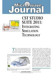
The CST STUDIO SUITE graphical user interface. 3D EM simulation of a mobile phone. Shown is the absolute value of the electric field.<br />
CST STUDIO SUITE<br />
CST STUDIO SUITE <strong>2012</strong> is the culmination of many years of<br />
research and development into the most accurate and efficient<br />
computational solutions for electromagnetic designs. It<br />
com prises CST’s tools for the design and optimization of devices<br />
operating in a wide range of frequencies – static to optical.<br />
Analyses may include thermal and mechanical effects, as well as<br />
circuit simulation.<br />
Complete Technology for 3D EM simulation enables easy access<br />
to a palette of solvers through a common user interface.<br />
System assembly and modeling facilitates multi-physics and<br />
co-simulation as well as the management of entire electromagnetic<br />
systems.<br />
What do RFIDs, Particle Guns and Car Antennas<br />
Have in Common?<br />
You can design all of these applications using CST STUDIO SUITE.<br />
It offers an extensive range of features and solvers <strong>suite</strong>d to<br />
all kinds of electromagnetic (EM) problems. While you can customize<br />
the package for specific applications, you can also easily<br />
switch to other design projects, exploiting your experience with<br />
the interface, workf<strong>low</strong>, and methodology. The solver range<br />
includes: time domain, frequency domain, integral equation,<br />
asymptotic, fast resonant, eigenmode, static and stationary<br />
fields, charged particles, temperature, mechanical stress, and<br />
circuit simulation.<br />
Overview<br />
3
CST STUDIO SUITE<br />
4<br />
CST STUDIO SUITE<br />
The integrated design environment gives access to the entire range of solver<br />
technology and facilitates circuit and multi-physics co-simulation.<br />
CST MICROWAVE STUDIO (CST MWS): the leading edge tool for the fast and accurate<br />
simulation of high frequency devices. Application areas include Microwaves & RF,<br />
EDA/Electronics, and EMC/EMI.<br />
CST EM STUDIO (CST EMS): for the design and analysis of static and <strong>low</strong> frequency<br />
EM applications such as motors, sensors, actuators, transformers, and shielding<br />
enclosures.<br />
CST PARTICLE STUDIO (CST PS): a highly specialized product for the fully consistent<br />
simulation of free moving charged particles. Applications include electron guns,<br />
cathode ray tubes, magnetrons, and wake fields.<br />
CST CABLE STUDIO (CST CS): for signal integrity and EMC/EMI analysis of cable<br />
harnesses.<br />
CST PCB STUDIO (CST PCBS): for the simulation of signal and power integrity and<br />
EMC/EMI on printed circuit boards.<br />
CST MPHYSICS STUDIO (CST MPS): for thermal and mechanical stress analysis.<br />
CST DESIGN STUDIO (CST DS): a versatile tool that facilitates 3D EM/circuit<br />
cosimulation and synthesis.<br />
Trademarks<br />
CST, CST STUDIO SUITE, CST MICROWAVE STUDIO, CST EM STUDIO, CST PARTICLE STUDIO, CST CABLE STUDIO,<br />
CST PCB STUDIO, CST MPHYSICS STUDIO, CST MICROSTRIPES, CST DESIGN STUDIO, PERFECT BOUNDARY<br />
APPROXIMATION (PBA), and the CST logo are trademarks or registered trademarks of CST in North America,<br />
the European Union, and other countries. Other brands and their products are trademarks or registered<br />
trademarks of their respective holders and should be noted as such.
Integrated Design Environment<br />
CST STUDIO SUITE benefits from an integrated<br />
design environment which gives<br />
access to its entire range of solver technology.<br />
This was developed in response<br />
to the growing demand for coupled<br />
problems and cosimulation:<br />
ó EM/circuit cosimulation<br />
ó Thermal analysis using all 3D<br />
electric loss results<br />
ó Analysis of mechanical stress<br />
ó Magnetostatic analysis of<br />
current f<strong>low</strong> fields<br />
ó Charged particle simulation with<br />
3D static and eigenmode fields<br />
ó Trace and cable currents for full<br />
3D EMC/EMI analysis<br />
CST MICROWAVE STUDIO (CST MWS)<br />
models can also be embedded in other<br />
RF/microwave circuit systems. The<br />
intuitive and easytouse graphical user<br />
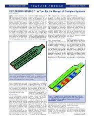
ParticleinCell simulation of a magnetron<br />
The true transient EM/circuit cosimulation of a subnanosecond pulse generator: a 60 MHz signal is converted<br />
into a sharp pulse by a strongly nonlinear steprecovery diode (SRD).<br />
interface is common to all of the CST 3D simulators. Several<br />
projects can be opened simultaneously in a single frontend<br />
using the multiple document interface.<br />
CST STUDIO SUITE comes with a schematic tool: CST DESIGN<br />
STUDIO (CST DS). Blocks, representing for example three dimensional<br />
CST MWS models or RFcircuits, can be used to setup<br />
systems. The decomposition of large microwave components<br />
into smaller subcomponents which can be handled with<br />
greater ease and speed, helps to increase simulation performance.<br />
True transient 3D EM/circuit cosimulation provides a powerful<br />
means to include nonlinear elements in 3D EM simulations to<br />
speed up multiport EM/circuit cosimulation. CST DS is the<br />
basis for the new System Assembly and Modeling (SAM) approach.<br />
The integrated optimizer offers various algorithms, local and<br />
global, which operate within and between the solver modules.<br />
Projects can be controlled using the VBA macro language and<br />
COM/DCOM implementation. Distributed computing and the<br />
job control center facilitate the management of projects and<br />
distribution of simulations on a network.<br />
CST STUDIO SUITE<br />
5
Simulation Performance<br />
6<br />
Simulation Performance<br />
Various meshing strategies for a simple sphere: staircase, tetrahedral linear, tetrahedral curved, and CST’s proprietory technology PBA.<br />
Simulation performance can be expressed<br />
as the time required to arrive at an<br />
accurate numerical simulation result<br />
from the initial design idea. The quest<br />
to solve ever larger and more complex<br />
models demands continuously increased<br />
performance. CST products have consistently<br />
achieved excellent performance<br />
on various levels: design intent capture<br />
in the modeler, workf<strong>low</strong> integration,<br />
advanced numerical algorithms, high<br />
performance computing, and automated<br />
evaluation and optimization. These<br />
are the essential ingredients for fast and<br />
successful design.<br />
Perfect Boundary Approximation<br />
Advanced features such as “bending” can facilitate and speedup the modeling process.<br />
CST gained a major competitive advantage with the introduction of PERFECT BOUNDARY<br />
APPROXIMATION [PBA]® technology into the Finite Integration Technique (FIT).<br />
The standard FDTD staircase grid is pretty efficient for a large number of mesh cells,<br />
but it does have a major drawback when it comes to the geometrical approximation of<br />
arbitrarily shaped structures.<br />
In a convergence study, the achieved accuracy of a staircase model improves s<strong>low</strong>ly<br />
and unsteadily and takes a large number of iterations. The geometrical precision<br />
achieved thanks to PBA enables smooth broadband convergence with a minimum<br />
number of passes. Tetrahedral meshing has more or less the opposite strengths<br />
and weaknesses of staircase meshing. PBA combines the advantages of both standard<br />
approaches and offers a superior solution for most applications.
dBi<br />
True Geometry Adaptation<br />
Traditional mesh refinement algorithms of tetrahedral frequency<br />
domain solvers do not improve upon the initial facetted<br />
representation of the structure. CST’s True Geometry Adaptation<br />
projects the refined mesh back onto the original model.<br />
In combination with arbitrary order curved elements, unprecedented<br />
accuracy for tetrahedral meshes can be achieved.<br />
Freq (GHz)<br />
Excellent agreement between measured and simulated broadband gain of a<br />
Satimo dualridge horn antenna.<br />
“The ERNI Ermet zeroXT connector is able to transmit<br />
differen tial signals up to a data rate of 10 Gbit/s [of a non-<br />
return zero code]. The complete design support, including<br />
the electromagnetic field analysis, the impedance calculation<br />
and the crosstalk analysis, was done using CST MICROWAVE<br />
STUDIO. Due to the accurate results, the connector could be<br />
manufactured, without a major re-design, in one pass.”<br />
Dr. Thomas Gneiting, AdMOS<br />
Coaxial waveguide after traditional mesh adaption approaches (left and middle)<br />
and true geometry adaption (right).<br />
Broadband Simulation<br />
Time domain simulation with CST MWS delivers a multitude<br />
of time and frequency domain results such as time signals and<br />
Sparameters, and farfields in the time and frequency domain.<br />
A transient simulation can provide results at many frequency<br />
points with an arbitrarily fine frequency resolution in just one<br />
simulation run.<br />
ERNI ermet zeroXT connector.<br />
Simulation Performance<br />
7
Simulation Performance<br />
8<br />
3D model of a package imported from Cadence Allegro Package Designer (APD)<br />
The Right Solver for the Job<br />
Simulation performance is strongly dependent on solver selection.<br />
The most important criteria are geometric complexity, resonant<br />
behavior, and electrical size. Choosing the optimal solver may<br />
dramatically decrease simulation time, but the weight of the<br />
individual criteria may not always be clear. The efficiency of<br />
the transient solver predestines it for detail rich packages,<br />
whereas frequency domain methods may excel at other electrically<br />
small applications. The Complete Technology approach of<br />
CST STUDIO SUITE enables you to choose comfortably between<br />
different solvers within one single user interface.<br />
Handling Details<br />
Many practical problems have different levels of detail in different<br />
regions of the simulation model. CST employs various technologies<br />
to optimize simulation performance for these cases. Mixed<br />
order elements in the frequency domain solver, as well as<br />
subgridding schemes for the broadband transient solvers, have<br />
been implemented. Compact models can replace fine details<br />
such as vents and seams by macro models. EM field results can be<br />
made available in other solvers through broadband field sources.
Sensitivity and Yield Analysis<br />
The sensitivity of a device’s performance to parameter changes<br />
may be a crucial property of a design. CST MICROWAVE STUDIO<br />
al<strong>low</strong>s you to evaluate the Sparameter dependencies on<br />
various model parameters on the basis of one single transient or<br />
frequency domain simulation. Since results for different model<br />
parameters can subsequently be derived without additional full<br />
wave simulations, yield analysis for complex three dimensional<br />
models becomes available at virtually no additional compu<br />
tational cost.<br />
Optimization<br />
Finding the best solution can be made considerably easier by<br />
using effective optimization strategies. CST STUDIO SUITE<br />
features versatile algorithms for local and global optimization,<br />
such as the Trust Region Method, the convergence of which<br />
can be accelerated additionally by employing sensitivity information,<br />
the NelderMead Simplex Method, and Particle Swarm<br />
optimizers. New to version <strong>2012</strong> is the CMAEvolution Strategy,<br />
a powerful global optimizer with good convergence behavior.<br />
Simulation Performance<br />
9
Simulation Performance<br />
10<br />
Distributed Computing<br />
In order to get your designs right quickly, you need automatic optimization and parameter<br />
studies. Wouldn’t it be nice to go on to your next task, while the simulation is<br />
performed in the back ground on another, dedicated machine? Or even better, run this<br />
job in parallel and cut down optimization time. CST’s distributed computing offers<br />
you a cost effective means of doing just this.<br />
Increased performance through distributed computing.
Cluster Computing<br />
CST’s parallelization based on the Message Passing Interface (MPI) enables<br />
the usage of computers in a network. It increases performance in two ways:<br />
1. Reduction of simulation time through parallel use of CPUs on several<br />
computer systems.<br />
2. Ability to simulate models previously too large to solve by using domain<br />
decomposition.<br />
Domain decomposition of a complex package: MPI is used to distribute the various parts over a network of several computers.<br />
Simulation Performance<br />
11
Simulation Performance<br />
12<br />
25<br />
20<br />
15<br />
10<br />
5<br />
0<br />
Surface currents excited by an invehicle antenna<br />
1 GPU<br />
(Tesla C1060)<br />
1 GPU<br />
(Tesla C2070)<br />
2 GPUs<br />
(Tesla C1060)<br />
Average speedup of solver loop using different GPUs<br />
4 GPUs<br />
(Tesla S1070)<br />
4 GPUs<br />
(Tesla S2050)<br />
Multi-CPU and GPU Computing<br />
Accurate conformal methods improve simulation performance<br />
by orders of magnitude compared to standard approaches.<br />
Additionally, efficient implementation on powerful hardware<br />
delivers a competitive edge.<br />
CST and Intel are collaborating to provide optimal performance<br />
on the latest multicore hardware platforms for users of<br />
CST STUDIO SUITE technology.<br />
Besides mainstream CPU development, graphics processing<br />
units (GPUs) enable <strong>low</strong>cost, high performance computing.<br />
CST is at the forefront of development, employing this technology<br />
to speed up accurate simulation.
CST Simulation Acceleration<br />
CST offers a multitude of simulation acceleration options such<br />
as multiCPU processing, GPU processing, cluster computing,<br />
and distributed computing. In order to help secure your investments<br />
as well as facilitate your choice of the most effective<br />
acceleration solution for a given simulation model, CST has<br />
introduced an acceleration token scheme. This enables<br />
greater versatility in accessing and combining high performance<br />
computing options. For example, one token can be used to<br />
increase the number of computers used in a cluster in one<br />
simulation run, and in the next run, to distribute a parameter<br />
process over the network.<br />
“Everything is going well with our use<br />
of CST, and your support is much appreciated.<br />
In fact, such prompt support<br />
is a major reason that WD will<br />
continue to utilize CST in the future<br />
(in addition to its technical<br />
advantages).”<br />
William Huber,<br />
Western Digital Corporation<br />
Distributed computing<br />
Parameters<br />
Ports<br />
Frequency points<br />
CST simulation acceleration options.<br />
Cluster computing<br />
MPI based<br />
parallelization<br />
Plane wave incident on an aircraft<br />
Hardware implementation<br />
GPU computing<br />
(CUDA)<br />
MultiCPU<br />
computing<br />
Simulation Performance<br />
13
Workf<strong>low</strong> Integration<br />
14<br />
Workf<strong>low</strong> Integration<br />
Using the Best-in-Class<br />
CST consistently promotes the bestinclass approach. We<br />
specialize in developing 3D EM software and provide straightforward,<br />
easytouse links with other bestinclass vendors,<br />
connecting all available expertise. A wide range of import/<br />
export filters enable the easy exchange of geometrical data<br />
with CAD tools. Furthermore, imported structures can be modified,<br />
parameterized, and used for optimization and design<br />
studies.<br />
Special interfaces to various EDA tools for signal integrity analysis<br />
and to RF circuit/system simulators for EM/circuit cosimulation<br />
enhance and unite the capabilities of different worlds. Moreover,<br />
the powerful VBA based and OLE compatible macro language<br />
al<strong>low</strong>s direct communication with programs like MATLAB® or<br />
MS Excel®.<br />
Circuit simulators<br />
Layout tools<br />
CAD tools<br />
CST modeler<br />
The import and export of structural information is fundamental<br />
to embedding an OBJ simulator in a design f<strong>low</strong>. CST STUDIO<br />
SUITE filter options include: SAT, STL, IGES, STEP, Nastran, VDAFS,<br />
Autodesk Inventor®, Pro/ENGINEER®, CATIA® v4 and v5, DXF,<br />
GDSII, Multilayer Gerber, ODB++, Altium® PCAD®, Altium Protel<br />
99SE, Cadence® Allegro®, Cadence SPECCTRA®, Mentor Graphics®<br />
Expedition, Mentor Graphics Board Station®, Mentor Graphics<br />
Hyperlynx®, Mentor Graphics PADS®, Zuken CR5000, Zuken<br />
Visula, Agilent ADS layouts, AWR Microwave Office® layouts,<br />
Sonnet® models, biological voxel data.<br />
Input Analysis Output<br />
Parameterized 3D-models<br />
Built-in optimizer<br />
CST STUDIO SUITE solver<br />
Multiphysics<br />
External tools/frameworks<br />
S-parameters<br />
Field results<br />
Spice models<br />
Optimized geometry<br />
COM/D-COM
Import Quality<br />
Import options are available in the majority of simulation tools<br />
nowadays, but their effectiveness is often impaired by seemingly<br />
insignificant details.<br />
There is nothing more frustrating than successfully importing<br />
98 % of a structure, as the missing 2 % may make it impossible<br />
to continue and it could cost days to fix the problem.<br />
Imports from EDA tools are particularly prone to small gaps<br />
and edges which un necessarily complicate the simulation<br />
model. CST MWS contains a sophisticated cleaning procedure<br />
as well as automatic healing; these features, combined with<br />
the robust mesher, enable effective simulation, even for quite<br />
corrupt CAD data.<br />
Detail of a camcorder: the complete device was modeled, simulated and<br />
subsequently modified to comply with FCC ClassB.<br />
Gauge for a speedometer driven by a stepping<br />
motor imported through the IGES interface.<br />
“CST specializes in passive 3D EM field simulation, and<br />
through partnerships with best-in-class active simulation<br />
tools, has made true co-simulation and co-optimization an<br />
everyday task. CST MICROWAVE STUDIO contains a powerful<br />
and easy to use solid modeler, and its powerful import filters<br />
enable the successful import and parameterization of complex<br />
geometrical data.”<br />
3D EM Application Team,<br />
Infineon Technologies AG<br />
Workf<strong>low</strong> Integration<br />
15
Complete Technology<br />
16<br />
Complete Technology<br />
Just a decade ago, experts argued which technology would dominate the 3D EM<br />
simulation market: time or frequency domain? Time domain was known for its<br />
ability to solve problems with a large number of mesh cells, whereas frequency<br />
domain – using tetrahedral instead of rectangular gridding – often offered better<br />
geometry approximation. Both methods have evolved a great deal since then; CST’s<br />
achievement in overcoming the disadvantages associated with the time domain’s<br />
staircase approximation has proved especially important. But it’s still true that no<br />
one method is perfect for every application. With this in mind, CST has developed<br />
frequency domain technology which complements the time domain as a general<br />
purpose solver. The TLM method complements the current range of solvers,<br />
particularly with respect to EMC/EMI applications. Moreover, in response to the<br />
demand for simulating ever larger structures, CST STUDIO SUITE includes an integral<br />
equation solver [with MLFMM], and an asymptotic solver.<br />
EMC analysis of a cable harness.
Why is it Important to Have a Complete Solution?<br />
CST software al<strong>low</strong>s you to switch from one solver to another easily, without changing<br />
the model and parametric settings. So you can choose the most appropriate method<br />
for each problem, thus minimizing your simulation run time. You only need a test<br />
password and you can try out any feature or solver. A nice side effect of this is that<br />
adding an additional solver is far more economical than buying a whole new package.<br />
RCS of a ship at 16.8 GHz<br />
Complete Technology<br />
17
Complete Technology<br />
18<br />
Current distribution on the metallic surface of a 155 m long ship excited by a plane wave of 400 MHz: the relative permitivity (81) and conductivity (0.01 S/m)<br />
of salt water are considered in the simulation.<br />
Confidence Through Cross Verification<br />
Sometimes simulation and measurements just don’t agree, but<br />
why? If the measurement was made by another work group<br />
they may quickly come to the conclusion that the simulation<br />
must be wrong. By running a simulation with both time and<br />
frequency domain solvers you can greatly increase confidence<br />
in your results. Reaching agreement with two different numerical<br />
methods proves that the deviation must have been caused by<br />
another factor, such as wrong material values or measurement<br />
failure.
True Transient EM/Circuit Co-Simulation<br />
A transient 3D EM/circuit cosimulation<br />
continuously exchanges currents and<br />
voltages at the ports between the CST<br />
MWS EM simulation and the circuit<br />
simulation in CST DS, while the signal<br />
propagates through the model. There<br />
are two major advantages to transient<br />
compared to standard EM/circuit cosimulation:<br />
UWB balanced amplifier for 35 GHz analyzed using<br />
true transient circuit/EM cosimulation.<br />
ó The time consuming derivation of the<br />
3D structure’s full Smatrix is no longer<br />
required since the circuit elements are<br />
placed directly into the electromagnetic<br />
field simulation. This can lead to tremendous<br />
simulation speedups, especially<br />
for PCBs with many ports and lumped<br />
elements.<br />
Imported PCB for power integrity analysis.<br />
ó Transient EM/circuit cosimulation<br />
also calculates the transient electromagnetic<br />
fields that result from the interaction<br />
with nonlinear elements such as<br />
diodes. The broadband nature of the<br />
transient simulation means that many<br />
harmonics are automatically taken into<br />
account.<br />
Line defect waveguide in a photonic crystal.<br />
Complete Technology<br />
19
Complete Technology<br />
20<br />
System Assembly and Modeling<br />
Complete Technology for EM simulation is one of the key<br />
strengths of CST STUDIO SUITE. Having access to a choice of<br />
available simulation methods al<strong>low</strong>s the user to select the<br />
optimal solver for the simulation of a given component. CST<br />
STUDIO SUITE <strong>2012</strong> takes simulation a step further: System<br />
Assembly and Modeling (SAM) provides an environment that<br />
simplifies the management of simulation projects in many ways.<br />
A device may consist of more than one component, each of<br />
which may require a different solution method for optimal<br />
simulation performance. The performance of such a large or<br />
complex system might be affected by interaction between<br />
components, so an optimization of the individual components<br />
might not be sufficient. An optimization of the entire system<br />
may be required. SAM provides a framework for addressing this<br />
requirement.<br />
In SAM a system is described by a schematic. In the simplest<br />
case this is one block representing a parameterized 3D model.<br />
The user defines the evaluations for this model by setting up<br />
simulation tasks. SAM helps you to compare the results of different<br />
solvers or model configurations within one simulation<br />
project. The user can also set up a linked sequence of solver runs.<br />
For example, the electromagnetic analysis of a filter could<br />
be fol<strong>low</strong>ed by a thermal simulation, then the filter’s resulting<br />
mechanical deformation could be determined, and finally this<br />
geometric change could be used in another electromagnetic<br />
simulation to investigate the detuning effect. All simulations<br />
and links can be defined easily in SAM to enable a seamless multiphysics<br />
work f<strong>low</strong>.<br />
System Assembly and Modeling: Various simulation projects can be derived from<br />
one master project, in this case an assembled antenna including Ortho Mode<br />
Transducer, Horn antenna and reflector.<br />
By adding other models to the schematic, the user can create<br />
a 3D system. SAM helps the user to define the geometric<br />
alignment of the various components. Simulation tasks can<br />
be defined that include single or multiple components and<br />
the user can specify which components should be simulated in<br />
3D, and which solver and CST simulation acceleration options<br />
should be used for those simulations. Components could also<br />
be represented simply by their Sparameter behavior or by an<br />
equivalent field source in the system simulation. This combination<br />
of different levels of simulation helps to reduce the computational<br />
effort required to analyze a complex model accurately.<br />
If required, SAM naturally also enables the user to create and<br />
simulate their system in full 3D.
Flexible array for 7 Tesla MRI consisting of eight striplinemeander elements. The gradient coil and<br />
a detailed human voxel model are considered during the simulation.<br />
Courtesy of Erwin L. Hahn Institute for MRI, Essen, Germany.<br />
Temperature after 30 min.<br />
Matching/tuning circuit for the MRI system.<br />
Complete Technology<br />
21
Complete Technology<br />
22<br />
Multi-Physics Analysis<br />
Electromagnetic design is undoubtedly the main goal of most<br />
CST STUDIO SUITE users. However EM fields create secondary<br />
effects. Metallic or dielectric losses could heat up and even<br />
damage the structure. Resulting forces could mechanically<br />
deform a device and change the electromagnetic behavior,<br />
for example, detune filters. CST MPHYSICS STUDIO contains a<br />
number of solvers for the analysis of stationary and transient<br />
thermal effects (including a bioheat description for biological<br />
tissues) as well as mechanical stress. The solver modules are<br />
tightly integrated for a seamless multiphysics workf<strong>low</strong>.<br />
“CST MICROWAVE STUDIO is our daily work-horse for fast and<br />
accurate EM simulation of passive microwave components.<br />
It lays a solid foundation from which Spinner provides high<br />
performance RF technology worldwide.”<br />
Dr. Martin Lorenz, Spinner GmbH<br />
Multiphysics analysis of a cavity filter (courtesy of Spinner GmbH):<br />
the electric field, the temperature distribution and the mechanical<br />
deformation, exaggerated plot.
CST – Computer Simulation Technology<br />
Founded in 1992, CST offers the market’s widest range of 3D electromagnetic field<br />
simulation tools.<br />
CST’s ground breaking Complete Technology complements its market and techno logy<br />
leading time domain solver, thus offering unparalleled accuracy and versatility for all<br />
applications.<br />
Our customers are market leaders in industries as diverse as Telecommunications,<br />
Defense, Automotive, Electronics, and Medical Equipment. Today CST employs 200<br />
sales, development, and support personnel, and enjoys a market share of over 30 % in<br />
high frequency 3D EM simulation.<br />
Foundation of CST’s Success<br />
CST’s success is based on the implementation of leading edge technology in a userfriendly<br />
interface.<br />
With the introduction of the proprietary PERFECT BOUNDARY APPROXIMATION [PBA]<br />
in 1998 with the first version of CST MICROWAVE STUDIO, CST’s flagship product, CST<br />
established a profound technical advantage.<br />
CST has built on this success, encouraging innovation and investing in product development.<br />
The resulting expansion in solver technology has created CST’s Complete<br />
Technology approach to simulation. This enables users to select the most appropriate<br />
method for their application and can offer additional security through cross verification.<br />
CST provides timely local support through its highly qualified technical support forces.<br />
Together with its committed distributors and representatives, CST supports its EM<br />
products in over 30 countries.<br />
CST<br />
23
© CST 2011 | CST – Computer Simulation Technology | info@<strong>cst</strong>.com | www.<strong>cst</strong>.com