Katalog_Prüftechnik_EN

Create successful ePaper yourself
Turn your PDF publications into a flip-book with our unique Google optimized e-Paper software.
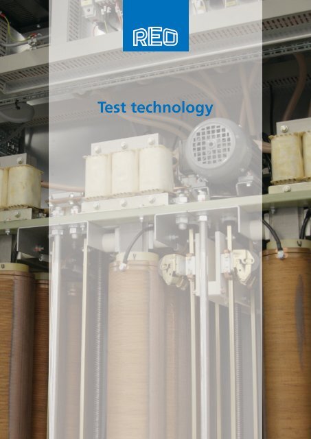
Test technology
Useful facts<br />
Useful facts about Test technology<br />
To ensure compliance with norms, guidelines and guarantee<br />
product safety, manufacturers and vendors of electrical and<br />
electronic components need to implement comprehensive<br />
validation testing. REO has specialized in this market for<br />
many years and is today the market leader in the area of test<br />
technology using variable-ratio transformer control. Whether<br />
for workshop tests on small loads or for testing converters<br />
on rail proving grounds – REO has the right solution; from an<br />
individual low-power supply all the way up to complex module<br />
testing stations with voltage supply, load unit and electronic<br />
control. REO can supply standard equipment or a device made<br />
to a customer‘s specifications, with exceptional functionality,<br />
like a regenerative unit to save energy, REO testing equipment<br />
causes no electromagnetic incompatibility and is an optimal<br />
solution for testing to the highest standard of quality.<br />
2
Service<br />
Training<br />
REO AG is your holistic partner in the area of inductive,<br />
resistive and electronic components and full solutions. A<br />
wide range of training services are also a key aspect of this<br />
partnership. These simplify commissioning of new devices<br />
and systems and guarantee hassle-free use during the whole<br />
product life cycle. Training sessions at your site or on the<br />
premises of REO AG form the basis for this. Our internal<br />
training managers instruct your employees in the technology<br />
and provide valuable tips on the correct and safe use of REO<br />
components. Our training sessions are available for both<br />
standard solutions and high-quality individualised components.<br />
Multimedia and easy to understand content supplement the<br />
training and also permit international deployment.<br />
Service<br />
Guarantee<br />
Winning quality – extra peace of mind, thanks to the<br />
expanded REO manufacturer’s guarantee.<br />
We believe in the quality of our own products and are<br />
confident of the durability of all components used, which is<br />
why we have extended the legal guarantee from one to two years.<br />
Safety<br />
We offer you devices with the highest possible operational<br />
safety. Should any unwanted events occur with any of our<br />
products, your professional emergency responder will be<br />
available to help you over the telephone free of charge. If the<br />
situation or query cannot be resolved over the telephone, you<br />
have the opportunity to have the defective device sent back<br />
after consultation.<br />
Repairs<br />
After telephone consultation, and after the defective<br />
product has been received, we can even offer you express<br />
repairs if possible. This minimises downtime in the event of a<br />
fault and guarantees a swift exchange.<br />
Hotline<br />
Our REO sales specialists look forward to giving you a helping<br />
hand. Contact your REO contact partner or call our hotline<br />
to receive further information about our services and the<br />
REO portfolio.<br />
3
Test technology<br />
Contents<br />
Useful facts about Variable-ratio<br />
transformers<br />
Variable-ratio transformers<br />
Three-phase toroidal variable-ratio<br />
transformers<br />
Single-phase column variable-ratio<br />
transformers<br />
Three-phase column variable-ratio<br />
transformers<br />
P. 5<br />
P. 6<br />
P. 7<br />
P. 8 - 9<br />
P. 10 - 11<br />
REO ohmic load units<br />
REOLOAD 101, 102<br />
REOLOAD 100<br />
REOLOAD 301<br />
REOLOAD 302<br />
REOLOAD 310<br />
REOLOAD 300<br />
P. 31<br />
P. 32<br />
P. 33<br />
P. 34<br />
P. 35<br />
P. 36<br />
P. 37<br />
Options for Variable transformers<br />
REOLINE with autowindings<br />
REOLINE with autowindings<br />
REO adjustable and constant voltage<br />
supplies<br />
P. 12<br />
P. 13<br />
P. 14<br />
P. 15<br />
Inductive loads - the individual<br />
components<br />
REOCHOKE 300<br />
REOCHOKE 300 / 69<br />
REOCHOKE NPT 892-2-450<br />
P. 38<br />
P. 39<br />
P. 40<br />
P. 41<br />
REOLAB 125<br />
P. 16<br />
Toroidal inductors NPT LD Td-AF<br />
P. 42<br />
REOLAB 126, 127, 128, 129<br />
P. 17<br />
Air-cored chokes<br />
P. 43<br />
REOLAB 123, 124<br />
P. 18<br />
Solenoid inductors NPT LD<br />
P. 44<br />
REOLAB 310, 312<br />
P. 19<br />
Iron-cored inductors for converters<br />
P. 45<br />
REOLAB 320<br />
REOLAB 330, 370<br />
REOLAB 340, 350<br />
P. 20<br />
P. 21<br />
P. 22<br />
Liquid-cooled inductors for test<br />
technology<br />
REO voltage stabilizers - optimal<br />
performance<br />
P. 46<br />
P. 47<br />
REOLAB 320, 520<br />
REOLAB 220<br />
REO voltage supplies - electronic solutions<br />
REOLAB 600<br />
P. 23<br />
P. 24<br />
P. 25<br />
P. 26 - 27<br />
Single-phase/three-phase voltage<br />
stabilizers<br />
Optional interfaces<br />
Modular construction of REO test<br />
equipment<br />
P. 48 - 49<br />
P. 50 - 51<br />
P. 52<br />
Mobile power supplies<br />
REOLOAD mobil<br />
P. 28<br />
P. 29<br />
Efficient principles of energy<br />
regeneration<br />
P. 53<br />
REOCHOKE 100<br />
P. 30<br />
4
Variable-ratio transformers<br />
Constant sinusoidal form for every application<br />
A variable-ratio transformer is used when output voltages<br />
are to be matched while constantly retaining sinusoidal form.<br />
REO variable-ratio transformers generate no interference or<br />
harmonics and are therefore particularly suitable for use in<br />
proving grounds or research institutes where high-frequency<br />
interference can cause problems with recorded test results.<br />
REO variable-ratio transformers are manufactured according<br />
to VDE 0552 and <strong>EN</strong> 61558-2-14 and use materials listed by<br />
UL to comply with international norms as well. Variable-ratio<br />
transformers with a compensation winding are included in our<br />
range of supplies for applications requiring a low voltage drop.<br />
REO takes a systematic approach in this field too: besides<br />
transformers, we offer complete high-voltage and heavycurrent<br />
testing equipment with the latest PLC controllers to<br />
ensure that testing functionality correspond to state of art<br />
requirements.<br />
All equipment is available in standard versions as well as<br />
special designs and requirements.<br />
Useful facts about Variable-ratio transformers
Variable-ratio transformers<br />
REOVAR<br />
Power range 0,23 - 25 kVA,<br />
Variable-ratio transformers<br />
A variable-ratio transformer is used when output voltages<br />
are to be matched while constantly retaining sinusoidal form.<br />
REO variable-ratio transformers generate no interference or<br />
harmonics and are therefore particularly suitable for use in<br />
proving grounds or research institutes where high-frequency<br />
interference can cause problems with recorded test results.<br />
REO variable-ratio transformers are manufactured according<br />
to VDE 0552 and <strong>EN</strong> 61558-2-14 and use materials listed by<br />
UL to comply with international norms as well. Variable-ratio<br />
transformers with a compensation winding are included in our<br />
range of supplies for applications requiring a low voltage drop.<br />
REO takes a systematic approach in this field too: besides<br />
transformers, we offer complete<br />
high-voltage and heavy-current testing equipment with the<br />
latest PLC controllers to ensure that<br />
testing functionality correspond to state of art requirements.<br />
All equipment is available in standard versions as well as<br />
special designs and requirements.<br />
Advantages<br />
• High-precision adjustment (turn-to-turn voltage approx. 0.7 V)<br />
• Generate no harmonic currents or voltages (clean sinusoidal<br />
output voltage, no harmonics)<br />
• No EMC interference<br />
Variable-ratio transformers<br />
Technical data<br />
RRT / RRTW / RRTGW<br />
Input voltage<br />
230 V<br />
Output voltage<br />
0 - 230 V oder 0 - 260 V<br />
Output current<br />
0,6 A to 96 A<br />
Output power<br />
0,22 kVA to 25 kVA<br />
Frequency range<br />
50 - 400 Hz<br />
Ambient temperature<br />
max. 40° C<br />
Vector group I 0<br />
IP Code IP 00 - IP 20<br />
Version: Series: RRT/RRTW M4 to <strong>EN</strong>10 and RRTP 2 x M 10 to 3 x <strong>EN</strong>10, current: 0.8 - 96 A Single-phase version with autowindings<br />
6
Three-phase toroidal<br />
variable-ratio transformers<br />
REOVAR<br />
Power range 0,69 - 25 kVA,<br />
Advantages<br />
• High-precision adjustment<br />
(turn-to-turn voltage only approx. 0.7 V)<br />
• Generate no harmonic currents or voltages<br />
(clean sinusoidal output voltage, no harmonics)<br />
• No EMC interference<br />
Three-phase toroidal<br />
variable-ratio transformers<br />
Three-phase toroidal variable-ratio transformers<br />
Technical data<br />
DRRTG/ DRRTO<br />
Input voltage<br />
3 x 400 V<br />
Output voltage<br />
3 x 0 - 400 V oder 3 x 0 - 450 V<br />
Output current<br />
3 x 0,6 A to 32 A<br />
Output power<br />
0,66 kVA to 24,9 kVA<br />
Frequency range<br />
50 - 400 Hz<br />
Ambient temperature<br />
max. 40° C<br />
Vector group<br />
Stern/Spar<br />
IP Code IP 00 - IP 20<br />
Version: Series: DRRTO DM 4 to DN 10 Three-phase version with autowindings<br />
7
Single-phase column variable-ratio transformers<br />
Single-phase column<br />
variable-ratio transformers<br />
Power range 2-300 kVA<br />
Advantages<br />
• High-precision adjustment (turn-to-turn voltage approx. 0.7 V)<br />
• Generate no harmonic currents or voltages (clean sinusoidal<br />
output voltage, no harmonics)<br />
• High overload capability for shorttime duty<br />
• No EMC interference<br />
Single-phase column<br />
variable-ratio transformers<br />
Earthquake restistant<br />
Manufactured by UL guidelines<br />
8
Technical data<br />
RTE<br />
Input voltage 230 V 400 V<br />
Output voltage 0 - 230 V 0 - 400 V<br />
Output current 8,5 - 435,0 A 250 A<br />
Output power<br />
2,0 - 100,0 kVA<br />
Frequency range<br />
50/60 Hz<br />
Vector group<br />
Auto<br />
IP Code IP 00 - IP 20<br />
RTE-S<br />
Input voltage 230 V 400 V<br />
Output voltage 0 - 230 V 0 - 400 V<br />
Output current<br />
47 - 1360 A<br />
Output power<br />
18 - 300 kVA<br />
Frequency range<br />
50/60 Hz<br />
Vector group<br />
Auto<br />
IP Code IP 00 - IP 20<br />
RTEU<br />
Input voltage 230 V 400 V<br />
Output voltage ± 0 - 230 V 2x ± 0 - 200 V<br />
Output current 8,5 - 435,0 A 250 A<br />
Output power<br />
2,0 - 100,0 kVA<br />
Frequency range<br />
50/60 Hz<br />
Vector group<br />
I0<br />
IP Code IP 00 - IP 20<br />
Single-phase column variable-ratio transformers<br />
RTEU-S<br />
Input voltage 230 V 400 V<br />
Output voltage ± 0 - 230 V 2x ± 0 - 200 V<br />
Output current<br />
47 - 1360 A<br />
Output power<br />
18,0 - 300,0 kVA<br />
Frequency range<br />
50/60 Hz<br />
Vector group<br />
Auto<br />
IP Code IP 00 - IP 20<br />
RTGE<br />
Input voltage 230 V 400 V<br />
Output voltage<br />
0 - 240 V; 0 - 440 V<br />
Output current<br />
8,3 - 290,0 A<br />
Output power<br />
2,0 - 128,0 kVA<br />
Frequency range<br />
50/60 Hz<br />
Vector group<br />
Ii0<br />
IP Code IP 00 - IP 20<br />
Version: RTE series: with autowindings, RTE-S series: autowound with compensation winding (low voltage drop), RTEU series: autowound with<br />
double brush, RTEU-S series: autowound with double brush and compensation winding (low voltage drop), RTGE series: with separate<br />
windings<br />
9
Three-phase column variable-ratio transformers<br />
Three-phase column<br />
variable-ratio transformers<br />
Power range 2-400 kVA<br />
Three-phase column<br />
variable-ratio transformers<br />
Earthquake restistant<br />
Manufactured by UL guidelines<br />
Technical data<br />
DRTE<br />
Input voltage 3 x 400 V 3 x 500 V<br />
Output voltage 3 x 0 - 400 V 3 x 0 - 500 V<br />
Output current<br />
3 x 8,7 - 208 A<br />
Output power<br />
6,0 - 153kVA<br />
Frequency<br />
50/60 Hz<br />
Vector group<br />
Star/auto<br />
IP Code IP 00 - IP 20<br />
DRTE-S<br />
Input voltage<br />
3 x 400 V<br />
Output voltage 3 x 0 - 400 V 3 x 0 - 690 V<br />
Output current<br />
3 x 21,5 - 557,0 A<br />
Output power<br />
15 - 400 kVA<br />
Frequency<br />
50/60 Hz<br />
Vector group<br />
Star/auto<br />
IP Code IP 00 - IP 20<br />
10
DRTEU<br />
Input voltage<br />
3 x 400 V<br />
Output voltage 3 x ± 0 - 400 V 3 x ± 0 - 500 V<br />
Output current<br />
3 x 8,7 - 208 A<br />
Output power<br />
6,0 - 153 kVA<br />
Frequency<br />
50/60 Hz<br />
Vector group<br />
Star/auto<br />
IP Code IP 00 - IP 20<br />
DRTEU-S<br />
Input voltage 3 x 400 V 3 x 0 - 400 V 3 x 0 - 660 V<br />
Output voltage<br />
3 x ± 0 - 400 V<br />
Output current 3 x 21,5 - 557,0<br />
Output power<br />
15 - 384 kVA<br />
Frequency<br />
50/60 Hz<br />
Vector group<br />
Star/auto<br />
IP Code IP 00 - IP 20<br />
DRTGE<br />
Input voltage<br />
3 x 400 V<br />
Output voltage 3 x 0 - 400 V 3 x 0 - 660 V<br />
Output current<br />
3 x 84 - 336,0 A<br />
Output power<br />
3 - 384 kVA<br />
Frequency<br />
50/60 Hz<br />
Vector group<br />
Star/auto<br />
IP Code IP 00 - IP 20<br />
Three-phase column variable-ratio transformers<br />
Version: DRTE series: autowindings, DRTE-S series: autowound with compensation winding (low voltage drop), DRTEU series: autowindings with<br />
double brush, DRTEU-S series: autowound double brush and compensation winding (low voltage drop), DRTGE series: with separate windings<br />
11
Options for Variable transformers<br />
Options for Variable transformers<br />
Manual drive by spindle<br />
Manual drive by spindle bevel gear drive<br />
Connection ±<br />
Motor drives<br />
Case designs<br />
Output voltage<br />
Further special designs<br />
Options for column variable-ratio transformers<br />
With ordering suffix „SP“ (vertical spindle)<br />
With ordering suffix „SPW“ (horizontal spindle)<br />
U<br />
AC motor drive 230 V 50/60 50Hz with ordering suffix „MoK“<br />
DS motor drive 3 x 400/230 V 50/60 Hz with ordering suffix „Mo“<br />
Are available with ingress protection IP 20 in standard paint finish RAL<br />
7035.<br />
If there is requirement for automatic output voltage regulation REO can<br />
supply control units which can help achieve this:<br />
NLR 7000 controller for three-phase motors<br />
NLR 2012 PID controller for AC motors<br />
On request<br />
Options for toroidal variable-ratio transformers<br />
Manual drive by spindle<br />
With ordering prefix „RRTW“ (vertical spindle)<br />
Manual drive by spindle bevel gear drive<br />
With ordering prefix „RRTSPW“ (horizontal spindle)<br />
Connection ± FZ 60, FZ 90, scale 90, scale 120<br />
Motor drives<br />
Case designs<br />
Output voltage<br />
Further special designs<br />
AC motor drive 230 V 50/60 Hz with ordering suffix - MoK<br />
DC motor drive 24 VDC with ordering suffix - MoG<br />
Are available in the standard IP Code IP 20 also in the standard paint<br />
finish RAL 7035.<br />
If there is requirement for automatic output voltage regulation REO can<br />
supply control units which can help achieve this:<br />
NLR 7000 controller for three-phase motors<br />
NLR 2012 PID controller for AC motors<br />
On request<br />
12
REOLINE with autowindings<br />
AC voltage supplies<br />
A way to vary AC voltages is essential in a test environment, and this<br />
portable laboratory power unit is designed to be easily and safely used<br />
in laboratories, proving grounds, workshops and service areas. The<br />
output voltage is continuously adjustable from 0...250 V. The absolute<br />
zero position results in a no-voltage condition at the zero position.<br />
Advantages<br />
• Mains lead 2 m long with plug with earth socket<br />
• Illuminated mains switch<br />
• Toroidal variable-ratio transformer with absolute zero position<br />
• Fuse protection on the secondary side<br />
• Analogue or digital voltmeter and ammeter at the output<br />
• Earthing contact socket or safety labs at the output<br />
• Carrying handles<br />
REOLINE with autowindings<br />
Plus AC-S/A<br />
Plus AC-S/D<br />
Technical data<br />
Plus AC-S/A, Plus AC-S/D<br />
Input voltage<br />
230 V<br />
Output voltage<br />
0 - 250 V<br />
Output current<br />
0,6 - 8 A<br />
Output power<br />
0,15 - 2,00 kVA<br />
Frequency<br />
50 / 60 Hz<br />
Vector group<br />
Auto<br />
Max. ambient temperature<br />
+ 40° C<br />
IP Code IP 40<br />
Produced in accordance with <strong>EN</strong> 61010-1 / VDE 0441 Teil 1<br />
13
REOLINE with autowindings<br />
AC voltage supplies<br />
REOLINE with autowindings<br />
A way to vary AC voltages is essential in a test environment, and this<br />
portable laboratory power unit is designed to be easily and safely used<br />
in laboratories, proving grounds, workshops and service areas.<br />
Advantages<br />
• Mains lead 2 m long with plug with earth socket<br />
• Illuminated mains switch<br />
• Toroidal variable-ratio transformer with absolute zero position<br />
• Fuse protection on the secondary side<br />
• Analogue or digital voltmeter and ammeter at the output<br />
• Earthing contact socket or safety labs at the output<br />
• Carrying handles<br />
The output voltage is continuously adjustable from 0...250 V. The<br />
absolute zero position results in a no-voltage condition at the zero<br />
position.<br />
Plus AC-S/A<br />
Plus AC-S/D<br />
Technical data<br />
Plus AC-SG/A, Plus AC-SG/D<br />
Input voltage<br />
230 V<br />
Output voltage<br />
0 - 250 V<br />
Output current<br />
3 x 0,6 - 8 A<br />
Output power<br />
0,15 - 2,00 kVA<br />
Frequency<br />
50/60 Hz<br />
Vector group<br />
Ii0<br />
Max. ambient temperature<br />
+ 40° C<br />
IP Code IP 40<br />
Produced in accordance with <strong>EN</strong> 61010-1 / VDE 0441 Teil 1<br />
14
REO adjustable and constant<br />
voltage supplies<br />
REO voltage supplies are free of electromagnetic interference<br />
and correspond with the applicable EC Directives (<strong>EN</strong> 61558-<br />
2-14 or the older VDE 0552).<br />
REO testing equipment is used in proving grounds,<br />
development laboratories, institutes, schools, universities,<br />
in industry and in all mobile stations (also in the automotive<br />
sector in particular). REO test equipment has made a name for<br />
itself by providing constant quality and ongoing continuous<br />
development - our REOLAB units are successfully used<br />
worldwide.<br />
REO adjustable and constant voltage supplies<br />
15
Single-phase voltage supplies<br />
Adjustable and constant voltage supplies<br />
REOLAB 125<br />
Advantages<br />
• No harmonic waves<br />
• No EMC interference<br />
• Clean sinusoidal form<br />
REOLAB 125<br />
Description<br />
Single-phase voltage supplies with separate windings and<br />
motor drive<br />
Technical data<br />
REOLAB 125*<br />
Input voltage<br />
230 - 1000 V<br />
Output voltage<br />
0 - 400 V<br />
Output current<br />
26 - 375 A<br />
Output power<br />
0 - 150 kVA<br />
Vector group<br />
Ii0<br />
IP Code IP 00 or IP 20<br />
Frequency range<br />
50/60 Hz<br />
*Other voltages and loads are also available on request. Different operating modes/concepts and industry interfaces are also possible.<br />
16
Single-phase voltage supplies<br />
Adjustable and constant voltage supplies<br />
Advantages<br />
• No harmonic waves<br />
• No EMC interference<br />
• Clean sinusoidal form<br />
REOLAB 126, 127, 128, 129<br />
Description<br />
Single-phase voltage supplies with separate windings and<br />
motor drive<br />
REOLAB 126, 127, 128, 129<br />
Technical data<br />
REOLAB 126, 127*<br />
Input voltage<br />
230 VAC or 400 VAC<br />
Output voltage<br />
0 - 230 VAC or 0 - 400 VAC<br />
Output current<br />
9 - 40 A<br />
Output power<br />
2,07 - 16 kVA<br />
Vector group<br />
Auto<br />
IP Code IP 20<br />
Regulation precision ± 1%<br />
REOLAB 128, 129*<br />
Input voltage<br />
230 VAC oder 400 VAC<br />
Output voltage<br />
0 - 230 VAC bzw. 0 - 400 VAC<br />
Output current<br />
10 - 40 A<br />
Output power<br />
2,3 - 16 kVA<br />
Vector group<br />
Separate windings<br />
IP Code IP 20<br />
Regulation precision ± 1%<br />
*Other voltages and loads are also available on request. Different operating modes/concepts and industry interfaces are also possible.<br />
17
Three-phase voltage supplies<br />
Adjustable and constant voltage supplies<br />
REOLAB 123, 124<br />
Advantages<br />
• No harmonic waves<br />
• No EMC interference<br />
• Clean sinusoidal form<br />
REOLAB 123, 124<br />
Description<br />
REOLAB 123<br />
Three-phase AC/DC voltage supplies with separate windings<br />
and motor drive for testing/developing e.g. AC and DC static<br />
converters or auxiliary converters<br />
REOLAB 124<br />
Three-phase AC/DC voltage supplies with separate winding<br />
and motor drive. Used for motor testing<br />
Technical data<br />
REOLAB 123*<br />
Input voltage<br />
3 x 400 VAC<br />
Output voltage<br />
0 - 2500 V or 0 - 5000 DC or 0 - 430 VAC<br />
Output current<br />
60 ADC, 30 ADC, 335 AAC<br />
Output power<br />
150 kW as standard version / 144 kVA<br />
Vector group<br />
Delta/Star/Star/2 x B6U/Ii0<br />
IP Code IP 20<br />
Frequency range<br />
50/60 Hz<br />
REOLAB 124*<br />
Input voltage<br />
3 x 400 VAC<br />
Output voltage<br />
0 - 500 VDC bzw. 3 x 0 - 600 VAC bzw. 0 - 300 DC<br />
Output current<br />
200 ADC, 3 x 200 AAC, 15 ADC<br />
Output power<br />
100 kW aas standard version / 208 kVA bzw. 4,5 kW<br />
Vector group<br />
Star/star/2 x B6U<br />
IP Code IP 20<br />
Frequency range<br />
50/60 Hz<br />
18<br />
*Other voltages and loads are also available on request. Different operating modes/concepts and industry interfaces are also possible.
Three-phase AC voltage supplies<br />
with autowindings + electrical<br />
voltage control<br />
Adjustable and constant voltage supplies<br />
Advantages<br />
• No harmonic waves<br />
• No EMC interference<br />
• Clean sinusoidal form<br />
REOLAB 310, 312<br />
Description<br />
REOLAB 310<br />
Three-phase voltage supplies with autowindings, motor drive<br />
and electronic control of the output voltage to approx. 1.5%<br />
regulation accuracy.<br />
REOLAB 312<br />
Three-phase voltage supplies with autowindings for manual<br />
adjustment of output voltage<br />
REOLAB 310, 312<br />
Technical data<br />
REOLAB 310*<br />
Input voltage<br />
3 x 400 V L/L bzw. 3 x 230 V L/N<br />
Output voltage 3 x 0 - 450 VAC (3 x 0 - 400 V)<br />
Output current<br />
3 x 10 - 100 A<br />
Output power<br />
7,8 bis 69 kVA as standard version<br />
Vector group<br />
Star/auto<br />
IP Code<br />
IP 20 in mobile housing<br />
Frequency range<br />
50/60 Hz<br />
Input voltage<br />
Output voltage<br />
Output current<br />
Output power<br />
Vector group<br />
IP Code<br />
Frequency range<br />
REOLAB 312*<br />
3 x 400 V L/L bzw. 3 x 230 V L/N<br />
3 x 0 - 450 VAC<br />
3 x 18 A<br />
14 kVA as standard version<br />
Star/auto<br />
IP 20 in mobile housing<br />
50/60 Hz<br />
*Other voltages and loads are also available on request. Different operating modes/concepts and industry interfaces are also possible.<br />
19
Three-phase AC voltage supplies<br />
with separate windings +<br />
automatic output regulation<br />
Adjustable and constant voltage supplies<br />
REOLAB 320<br />
Advantages<br />
• No harmonic waves<br />
• No EMC interference<br />
• Clean sinusoidal form<br />
Description<br />
Three-phase-voltage supplies with separate windings, motor<br />
drive and electronic voltage control with safety circuits and<br />
warning beacons are suitable for the endurance testing of<br />
cable terminations. The regulation precision of the output<br />
voltage is approx. 1.5%.<br />
REOLAB 320<br />
In conjunction with the REOLAB 220 as a heavy current<br />
source for temperature rise testing, the REOLAB 320 can<br />
be used for insulation tests on cables and cable terminations<br />
Technical data<br />
Input voltage<br />
Output voltage<br />
Output current<br />
Output power<br />
Vector group<br />
IP Code<br />
Frequency range<br />
REOLAB 320*<br />
3 x 400 V L/L or 3 x 230 V L/N<br />
3 x 0 - 3000 VAC, 3 x 0 - 4000 VAC, 3 x 0 - 5000 VAC<br />
3 x 0,25 AAC<br />
1,3 - 2,16 kVA<br />
Star/star<br />
IP 20 in mobile housing<br />
50/60 Hz<br />
20<br />
*Other voltages and loads are also available on request. Different operating modes/concepts and industry interfaces are also possible.
Three-phase AC voltage supplies<br />
with separate windings +<br />
automatic output regulation<br />
Adjustable and constant voltage supplies<br />
Advantages<br />
• No harmonic waves<br />
• No EMC interference<br />
• Clean sinusoidal form<br />
REOLAB 330, 370<br />
Description<br />
Three-phase-voltage supplies with separate windings, motor<br />
drive and electronic control of the output voltage to approx.<br />
1.5%<br />
REOLAB 330, 370<br />
Technical data<br />
Input voltage<br />
Output voltage<br />
Output current<br />
Output power<br />
Vector group<br />
IP Code<br />
Frequency range<br />
REOLAB 330*<br />
3 x 400 V L/L or 3 x 230 V L/N<br />
3 x 0 - 450 VAC<br />
3 x 12 A - 3 x 63 AAC<br />
9,4 - 49 kVA as standard version<br />
Star/star<br />
IP 20 in mobile housing<br />
50/60 Hz<br />
Input voltage<br />
Output voltage<br />
Output current<br />
Output power<br />
Vector group<br />
IP Code<br />
Frequency range<br />
REOLAB 370*<br />
3 x 400 V L/L or 3 x 230 V L/N<br />
3 x 0 - 520 VAC<br />
3 x 10 AAC<br />
9 kVA as standard version<br />
Star/star<br />
IP 20 in mobile housing<br />
50/60 Hz<br />
*Other voltages and loads are also available on request. Different operating modes/concepts and industry interfaces are also possible.<br />
21
Three-phase AC voltage supplies<br />
Adjustable and constant voltage supplies<br />
REOLAB 340, 350<br />
Advantages<br />
• No harmonic waves<br />
• No EMC interference<br />
• Clean sinusoidal form<br />
Description<br />
REOLAB 340<br />
These three-phase voltage supplies with separate windings<br />
regulate the output voltage with an accuracy of approx. 1.5%<br />
from the final value.<br />
Switchable output voltage ranges ensure a low voltage drop.<br />
These transformers are rated in accordance with the existing<br />
harmonic of the test specimens so that the voltage drop of the<br />
harmonic affects the sinusoidal form of the output voltage as<br />
little as possible. Suitable for testing frequency converters and<br />
motors in accordance with IEC 60 034.<br />
REOLAB 350<br />
These three-phase and single-phase voltage supplies with<br />
separate windings have a variable single-phase output voltage<br />
and a mains frequency of 16 2/3 Hz. The REO sinewave filter<br />
ensures a clean output voltage. Assisted by electronic voltage<br />
control, the output voltage can be regulated to approx. 1%.<br />
For testing railway applications<br />
REOLAB 340<br />
Technical data<br />
REOLAB 340*<br />
Input voltage<br />
3 x 400 V L/L or 3 x 230 V L/N<br />
Output voltage<br />
3 x 50 - 700 VAC<br />
Output current<br />
3 x 400 A falling to 3 x 291 A<br />
Output power<br />
max. 381 kVA<br />
Vector group<br />
Star/auto<br />
IP Code IP 20<br />
Frequency range<br />
50/60 Hz<br />
REOLAB 350*<br />
Input voltage<br />
3 x 400 / 230 VAC<br />
Output voltage<br />
700 - 1300 VAC 16 2/3 Hz<br />
Output current<br />
143 A<br />
Output power<br />
100 - 185.9 kVA<br />
Vector group<br />
Separate windings<br />
IP Code IP 20<br />
Frequency range<br />
50/60 Hz<br />
22<br />
*Other voltages and loads are also available on request. Different operating modes/concepts and industry interfaces are also possible.
Three-phase DC high-voltage<br />
power supplies<br />
Adjustable and constant voltage supplies<br />
Description<br />
Three-phase DC high-voltage power supplies with separate<br />
windings, motor drive and electronic control of the output<br />
voltage to approx. 1.0%, with short-circuit proof DC output.<br />
This three-phase DC high-voltage power supply is suitable<br />
for the development and testing of frequency converters for<br />
railway engineering. It is situated in development laboratories,<br />
proving grounds, test institutes, schools and universities.<br />
Because of the high DC output voltage, appropriate safety<br />
measures have been taken, such as:<br />
• Emergency-off circuit with external inputs and outputs<br />
as double-pole potential-free contacts for emergencyoff<br />
circuits and safety circuits<br />
• Warning lights and additional connections for external<br />
warning systems.<br />
• Discharge circuit for the intermediate-circuit capacitor<br />
• Earth trip with compressed-air drive to short out and earth<br />
the DC output<br />
To ensure safety, in the event of mains failure, the DC output<br />
is shorted out and earthed by the compressed-air drive.<br />
REOLAB 420<br />
REOLAB 320, 520<br />
Technical data<br />
REOLAB 420*<br />
Input voltage<br />
3 x 400 V L/L or 3 x 230 V L/N<br />
Output voltage<br />
0 - 12000 VDC<br />
Output current<br />
2 x 20 - 300 A<br />
Output power<br />
100 kW - 800 kW as standard version<br />
Vector group<br />
Delta/Star/star/2 x B6U<br />
IP Code IP 20<br />
Frequency range<br />
50/60 Hz<br />
REOLAB 520*<br />
REOLAB 520 supplies have the same design as REOLAB 420 supplies, but with an additional separately regulated DC output of 0 - 150 VDC,<br />
30 AC or 50 ADC for the control voltage of power semiconductors. This can be augmented with an optional uninterruptible power supply (UPS)<br />
so that, even in the event of a mains failure, the power semiconductors still receive control voltage for a certain period to ensure that they can be<br />
safely shut down.<br />
*Other voltages and loads are also available on request. Different operating modes/concepts and industry interfaces are also possible.<br />
23
Three-phase AC heavy-current<br />
power supplies<br />
Adjustable and constant voltage supplies,<br />
for temperature rise testing<br />
REOLAB 220<br />
Description<br />
These three-phase heavy-current power supplies have separate<br />
windings and separate electronic output current control. The<br />
separate modular construction of the control section and the<br />
heavy current section makes it possible, to connect different<br />
heavy current transformers to the control section to ensure<br />
flexibility.<br />
REOLAB 220<br />
In connection with REOLAB 320<br />
Technical data<br />
REOLAB 220*<br />
Input voltage<br />
3 x 400 VAC 50/60 Hz<br />
Output voltage<br />
3 x 0 - 10 V per phase<br />
Output current<br />
bis 3 x 10.000 A<br />
Output power<br />
bis 300 kVA<br />
Vector group<br />
Star/open/open/open<br />
IP Code IP 20<br />
Application: Temperature rise testing of components such as cables and contacts, Low-voltage distribution, Switchgear with low-ohmic impedances<br />
24<br />
*Other voltages and loads are also available on request. Different operating modes/concepts and industry interfaces are also possible.
REO voltage supplies -<br />
electronic solutions<br />
Adjustable and constant voltage supplies<br />
In addition to our transformer solutions for the regulation of<br />
AC voltages whose advantages lie in their robust construction<br />
and favourable short-term overload capacity, REO also makes<br />
electronic voltage supplies.<br />
Advantages<br />
• Very high dynamics (short response times and control times,<br />
very precise regulation)<br />
• Variable frequency<br />
• Freedom from maintenance<br />
REO voltage supplies - electronic solutions
Three-phase AC high-voltage<br />
power supplies<br />
Adjustable and constant voltage supplies,<br />
Electronic solution<br />
REOLAB 600<br />
All power supplies can be fitted as an option with a computer<br />
interface for external operation. This equipment can of<br />
course be designed with other technical parameters to suit a<br />
customer‘s wishes.<br />
REOLAB 600<br />
Description<br />
These three-phase AC supplies with separate windings have<br />
an adjustable variable output voltage and a variable output<br />
frequency. These AC supplies are suitable for simulating<br />
a mains network and for testing devices, components or<br />
installations typically for 60-Hz networks. They consist of<br />
an inverter with adjustable frequency and, ensure with REO<br />
sinewave filters, a clean sinusoidal form at the output.<br />
26
Technical data<br />
REOLAB 600<br />
Input voltage<br />
3 x 400 V L/L or 3 x 230 V L/N<br />
Output voltage max.<br />
3 x 0 - 500 VAC<br />
Output current<br />
3 x 22 A<br />
Output frequency<br />
16 - 1600 Hz variabel<br />
Output power<br />
19 kVA as standard version<br />
Vector group<br />
Delta / Star<br />
IP Code IP 20<br />
Frequency range<br />
50/60 Hz<br />
REOLAB 600<br />
Block diagram<br />
27
Three-phase AC/DC resistive<br />
load unit<br />
Mobile voltage supplies<br />
REOLOAD mobil<br />
Description<br />
These resistive load units make it possible to test auxiliary<br />
converters and DC battery-charging units in train carriages for<br />
correct function while under load. Since they often have to be<br />
used in large halls, the supplies can be carried by vehicles via<br />
a shaft to the train carriage to be tested. A 20-metre mains<br />
lead is supplied with plug with earthing contact. The resistance<br />
steps are connected to safety laboratory sockets. The individual<br />
stages can be switched on and off while under load. Operation<br />
and display are on an inbuilt panel. This equipment can of<br />
course be designed with other technical parameters to suit a<br />
customer‘s wishes.<br />
Three-phase AC/DC resistive load unit<br />
Technical data<br />
REOLOAD 300 AC mobil 75,9 kW<br />
Voltage 3 x 400 VAC 50/60 Hz / 75,9 kW; IP code: IP 20<br />
Current 3 x 1 A 2 x 3 x 2 A 3 x 5 A 3 x 10 A 2 x 3 x 20 A 3 x 50 A<br />
Power 0,69 kW 2 x 1,38 kW 3,45 kW 6,9 kW 2 x 13,8 kW 34,5 kW<br />
REOLOAD 100 DC mobil 12,65 kW<br />
Voltage 110 VDC 12,65 kW; IP code: IP 20<br />
Current 1 A 2 A 4 A 8 A 10 A 2 x 20 A 50 A<br />
Power 0,11 kW 0,22 kW 0,44 kW 0,88 kW 1,1 kW 2 x 2,2 kW 5,5 kW<br />
REOLOAD 100 DC mobil 8,26 kW<br />
Voltage 72 VDC 8,26 kW; IP code: IP 20<br />
Current 1 A 2 A 4 A 8 A 10 A 2 x 20 A 50 A<br />
Power 0,072 kW 0,14 kW 0,28 kW 0,57 kW 0,72 kW 2 x 1,44 kW 3,6 kW<br />
REOLOAD 100 DC mobil 4,13 kW<br />
Voltage 36 VDC 4,13 kW; IP code: IP 20<br />
Current 1 A 2 A 4 A 8 A 10 A 2 x 20 A 50 A<br />
Power 0,036 kW 0,072 kW 0,14 kW 0,28 kW 0,36 kW 2 x 0,72 kW 1,8 kW<br />
REOLOAD 100 DC mobil 2,76 kW<br />
Voltage 24 VDC 2,76 kW; IP code: IP 20<br />
Current 1 A 2 A 4 A 8 A 10 A 2 x 20 A 50 A<br />
Power 0,024 kW 0,048 kW 0,096 kW 0,19 kW 0,24 kW 2 x 0,48 kW 1,2 kW<br />
29
Single-phase test inductors<br />
Mobile voltage supplies<br />
Description<br />
REOCHOKE 100<br />
For testing frequency converters with inductive load. Load<br />
testing with a high reactive current component causes the<br />
reactive current component to be compensated by the<br />
capacitance in the DC intermediate circuit, so that only the<br />
losses are supplied to the frequency converter to be tested,<br />
e.g. with the REOLAB mobile 70 kW mobile AC/DC supply.<br />
Approx. 70% to 80% of the energy costs for testing are saved<br />
thereby.<br />
REOCHOKE 100 mobil<br />
0,25 mH / 2000 A<br />
Technical data<br />
REOCHOKE 100 mobil 0,25 mH / 2000 A<br />
Inductance 0,25 mH - 0 % + 10 %<br />
Voltage<br />
4500 VAC 50 Hz<br />
Current<br />
2000 A DB max. 4000 A KB<br />
Power<br />
157 kVA DB max. 628 kVA KB<br />
IP Code IP 44<br />
30
REO ohmic load units<br />
Starting with the manufacture of arc lamps for the cinema<br />
industry, REO has been utilising its knowledge and expertise in<br />
the electrotechnical field for 80 years. Constant development<br />
means that REO now offers a very wide portfolio of testing<br />
systems and products to allow testing of converters to braking<br />
resistors and everything in-between. Ohmic load units are used<br />
when power supply systems or other test specimens, such as<br />
switches, contacts or transformers, have to be loaded with<br />
a resistive load. Ohmic load units are used in development<br />
laboratories, proving grounds, test institutes, schools and<br />
universities.<br />
REO ohmic load units<br />
31
Single-phase resistive loads<br />
Ohmic load units<br />
REOLOAD 101, 102<br />
Advantages REOLOAD 101<br />
• Seven fixed stages<br />
• Fine control stage for testing contacts, static converters,<br />
witched-mode power supplies<br />
• Remote control via 24 VDC coupling relay; the individual<br />
stages can be switched on and off while under load<br />
• Connections are made via laboratory screw terminals and<br />
plug and socket connections. The individual stages can be<br />
operated via switches in local operation, and via potentialfree<br />
contacts<br />
• controlled by the 24 VDC coupling relay for remote operation.<br />
Advantages REOLOAD 102<br />
• Two fixed stages for testing generators<br />
• Batteries for simulating different types of load<br />
• The individual stages can be switched off while under load<br />
• Connections via laboratory screw terminals and plug and<br />
socket connections<br />
• Built-in analogue voltmeter and ammeter<br />
REOLOAD 101<br />
Technical data<br />
REOLOAD 101*<br />
Voltage max.<br />
230 V 50 / 60 Hz<br />
Resistance values<br />
1 - 10.000 Ohm<br />
Current<br />
0,1 - 250 A<br />
Precision of resistances +/- 5 %<br />
IP Code IP 20<br />
REOLOAD 102*<br />
Voltage max.<br />
1000 V AC oder DC<br />
Resistance values<br />
1 - 2500 Ohm<br />
Current<br />
max. 250 A<br />
Power<br />
5 kW, 10 kW, 15 kW, 20 kW and 25 kW<br />
Precision of resistances +/- 5 %<br />
IP Code IP 20<br />
32<br />
*This equipment can of course be designed with other technical parameters to suit a customer‘s wishes.
Single-phase resistive loads<br />
Ohmic load units<br />
Advantages<br />
REOLOAD 100<br />
• 17 fixed stages for testing switch contacts in accordance<br />
with IEC 60669-1-3.1 and IEC 61058-1/A2<br />
• All 17 stages are connected in series and can be bridged via<br />
contactors.<br />
• High precision<br />
• The required resistance values are able to be set via Ethernet<br />
connection<br />
• Low-inductance<br />
• Switching by means of contactors while ON load<br />
REOLOAD 100<br />
Technical data<br />
REOLOAD 100<br />
Resistance Current Power Tolerance Voltage max. Total power of all resistances<br />
0,1 Ω 16 A 25,6 W<br />
0,2 Ω 16 A 51,2 W<br />
0,3 Ω 16 A 76,8 W<br />
0,4 Ω 16 A 102,4 W<br />
1 Ω 16 A 256 W<br />
2 Ω 16 A 512 W<br />
3 Ω 16 A 768 W<br />
4 Ω 16 A 1024 W<br />
10 Ω 16 A 2560 W<br />
10 Ω 15 A 4500 W<br />
+/- 5%<br />
265 VAC or less from<br />
the 0.1 ohm to the 10<br />
ohm stage<br />
17,091 kW<br />
30 Ω 10 A 3000 W<br />
40 Ω 7,5 A 2250 W<br />
100 Ω 3 A 900 W<br />
200 Ω 1,5 A 450 W<br />
300 Ω 1 A 300 W<br />
400 Ω 0,75 A 225 W<br />
1000 Ω 0,3 A 90 W<br />
33
Three-phase resistive loads<br />
Ohmic load units<br />
Advantages<br />
REOLOAD 301<br />
• Ten fixed stages per unit for testing contacts, static converters<br />
and switched-mode power supplies with active current<br />
• Individual stages are switched on and off with rotary switches<br />
• The three units can be switched for single-phase and<br />
three-phase operation<br />
• Manual changeover by means of solid conductor links,<br />
allows versatile resistances and currents settings.<br />
• Connections via laboratory screw terminals and plug and<br />
socket connections inside the switch cabinet<br />
• Three standard sizes for selection:<br />
REOLOAD 301<br />
Technical data<br />
REOLOAD 301*<br />
REOLOAD 301 / 69<br />
230 V<br />
69 kW<br />
REOLOAD 301 / 120 400 V 10 stages, each 10 A<br />
120 kW<br />
REOLOAD 301 / 201 690 V 207 kW<br />
IP class IP 20<br />
*This equipment can of course be designed with other technical parameters to suit a customer‘s wishes.<br />
34
Three-phase resistive loads<br />
Ohmic load units<br />
Advantages<br />
• Eight fixed stages of three-phase alternating current for testing<br />
power supplies and temperature testing with active current<br />
regulation<br />
• Individual stages can be switched on and off while under load<br />
by means of rotary switches<br />
• True effective display by digital ammeter (96 x 48 mm) in the<br />
operating panel<br />
• Connections to safety laboratory sockets 4 mm<br />
REOLOAD 302<br />
REOLOAD 302<br />
Technical data<br />
REOLOAD 302*<br />
Resistance Currents Power Nominal voltage Total power IP Code<br />
3 x 2300 R 3 x 0,1 A 69 W<br />
3 x 1150 R 3 x 0,2 A 138 W<br />
3 x 575 R 3 x 0,4 A 276 W<br />
3 x 288 R 3 x 0,8 A 552 W<br />
3 x 230 R 3 x 1 A 690 W<br />
3 x 115 R 3 x 2 A 1380 W<br />
3 x 57,5 R 3 x 4 A 2760 W<br />
3 x 28,8 R 3 x 8 A 5520 W<br />
3 x 400 V L/L or<br />
3 x 230 V L/N 50/60<br />
Hz<br />
11,385 kW IP 20<br />
*This equipment can of course be designed with other technical parameters to suit a customer‘s wishes.<br />
35
Three-phase resistive loads<br />
Ohmic load units<br />
REOLOAD 310<br />
With optional liquid cooling, our test equipment combines<br />
compact construction, low weight and high protection class.<br />
When using this cooling method, much less waste heat in<br />
total is dissipated at the units themselves - this is a great<br />
advantage, in particular in smaller rooms or at high ambient<br />
temperatures. Another benefit of this system is that energy<br />
Advantages<br />
• Four fixed stages of three-phase alternating current for<br />
testing auxiliary converters with active current regulation<br />
• Individual stages can be switched on and off by means of<br />
illuminated push-buttons while ON load<br />
• Display of voltages, currents and direction of rotation<br />
• Line side inductors for damping voltage spikes<br />
• Outputs for measuring current and voltage<br />
• Connections to suitable terminals with the control housing<br />
taken away by the water can be sustainably integrated into<br />
the company heating process by REO liquid-cooled resistive<br />
load units. This can contribute positively to the energy<br />
efficiency of the whole company.<br />
REOLOAD 310<br />
Technical data<br />
REOLOAD 310*<br />
Nominal voltage<br />
3 x 440 V L/L or 3 x 254 V L/N 50/60 Hz<br />
Currents 3 x 8 A 3 x 15,7 A 3, x 31,5 A 3, x 63 A<br />
Power 6 kW 12 kW 24 kW 48 kW<br />
Total power<br />
90 kW<br />
Frequency<br />
50/60 Hz<br />
IP Code IP 20<br />
*This equipment can of course be designed with other technical parameters to suit a customer‘s wishes.<br />
36
Water-cooled resistive loads<br />
Water-cooled load units<br />
Description<br />
Example of a client-specific resistive load unit that consists<br />
of 15 resistance groups (liquid-cooled) and 4 rheostats with<br />
AC motor drive. All resistances are connected via contactors<br />
that are controlled via 24 VDC relays. Two stainless steel<br />
distributors are built in for connecting the water cooling.<br />
Technical data<br />
All resistance groups can be hydraulically regulated or<br />
switched individually. All fittings for the cooling circuit are in<br />
stainless steel. The resistances and the control are connected<br />
to suitable terminations.<br />
REOLOAD 300<br />
REOLOAD 300<br />
Nominal voltage<br />
3 x 440 V L/L or 3 x 254 V L/N; 10/60 Hz<br />
Total power<br />
253,45 kW<br />
Frequency<br />
50/60 Hz<br />
Duty cycle 100 %<br />
Res. tolerance +/- 5%<br />
Cooling Water/Glykol (70:30)<br />
Volume of flow<br />
ca. 800 l/min<br />
Flow temperature<br />
max. 25° C<br />
37
Inductive loads - the individual components<br />
Inductive loads - the individual<br />
components<br />
Inductive loads are usually specially designed for an application<br />
and with reference to the applicable norms. These standards<br />
detail the tests required but also the test setups and<br />
procedures. The inductances are specially adapted to the area<br />
of application so an optimal solution may be provided.<br />
Inductive load units are used when power supply systems or<br />
other test specimens, such as switches, contacts or frequency<br />
converters have to be loaded with a standardized effective and<br />
reactive power.<br />
Frequency converters that are loaded with an inductive load<br />
require substantially less energy when being tested, because<br />
compensation is effected by the DC intermediate-circuit<br />
capacitor. For this reason, only the losses are supplied for the<br />
testing, as a result of which an energy saving of approx.<br />
70% - 80% can be achieved during such tests.<br />
Additional resistive loads are required to achieve the cos phi<br />
(power factor) values required for testing. This particularly<br />
applies to switch and contact testing. The application is used<br />
in development laboratories, proving grounds, test institutes,<br />
schools and universities.<br />
Please feel free to contact us for individual adjustment<br />
measures or accessories.<br />
38
Three-phase inductive loads<br />
Inductive load units<br />
Description<br />
The three-phase-inductive load consists of three iron-cored<br />
inductors, each with three tappings, and is used for testing<br />
static converters and switched-mode power supplies. The<br />
individual tappings are connected directly to the inductor. A<br />
REO DC closed loop current transformer is built in for each<br />
phase for measuring current.<br />
REOCHOKE 300<br />
REOCHOKE 300<br />
Technical data<br />
REOCHOKE 300<br />
Voltage<br />
3 x 4000 V<br />
Inductance values<br />
3 x 1 mH with tappings at 0,75 mH, 0,5 mH and 0,25 mH<br />
Current<br />
3 x 1500 A<br />
Tolerance of the inductor +/- 10 %<br />
IP Code IP 20<br />
39
Three-phase inductive loads<br />
Inductive load units<br />
REOCHOKE 300 / 69<br />
Description<br />
Infinitely adjustable three-phase inductive loads consisting<br />
of a three-phase column variable-ratio transformer and a<br />
downstream three-phase iron-cored inductor on the secondary<br />
side for testing static converters and power supply units with<br />
reactive current. The reactive current can be set from approx.<br />
5% to 100% by means of min/max push-buttons via the<br />
variable-ratio transformer. With built-in digital measuring<br />
equipment for current and voltage.<br />
REOCHOKE 300 / 69<br />
Technical data<br />
REOCHOKE 300 / 69<br />
Voltage<br />
3 x 400 V<br />
Frequency<br />
50 Hz<br />
Current<br />
3 x 2 - 100 A<br />
Power<br />
3 x 0,46 - 23 = 69 kVA<br />
Connection<br />
Star/auto<br />
AC motor drive<br />
230 V 50 Hz<br />
Actuating time approx.<br />
30 seconds<br />
IP Code IP 20<br />
40
Iron-cored inductors<br />
Inductive load units, Inductors for testing switches and relays<br />
Advantages<br />
• Matched linearity to the application, so no saturation in the<br />
relevant working range<br />
• Several tappings, so there amount of inductors can be<br />
reduced<br />
• Matched winding resistance, therefore reduced number of<br />
external resistors<br />
• Designed for continuous load and short-time loading<br />
• Costs reduced by optimized weight and dimensions<br />
• High nominal voltage, standard up to 1000 V<br />
Description<br />
Electrical switches have to pass many different tests during the<br />
approval phase. Some of these tests concern their switching<br />
behaviour under various test conditions. A switch is tested<br />
under nominal load, overload and with several values of cos<br />
phi (power factor). Besides continuous loading, switching on<br />
and off processes are also investigated. Throughout testing,<br />
it is crucial for the set parameters not to be altered. Air-cored<br />
inductors were used as inductive loads in the past, because<br />
they almost never saturate. Air-cored inductors are however<br />
larger and have a stronger leakage field than comparable<br />
iron-cored inductors with corresponding magnetic energy. In<br />
order to set the relevant cos phi (power factor) value, matched<br />
resistances must be connected up in addition. In order to meet<br />
all the required test points, many various inductive and ohmic<br />
loads must be available.<br />
REOCHOKE NPT 892-2-450<br />
REOCHOKE NPT 892-2-450<br />
Relevant norms: IEC 60669 und IEC 61058<br />
Technical data<br />
REOCHOKE NPT 892-2-450<br />
Tapping Inductance L Nominal current I rms<br />
Linear up to I lin<br />
Nominal voltage U r<br />
IP Code<br />
L 2<br />
115 mH<br />
8 A<br />
L 3<br />
190 mH 8 A<br />
L 4<br />
240 mH 6 A<br />
L 5<br />
300 mH 6 A<br />
2 A<br />
L 6<br />
370 mH 5 A<br />
L 7<br />
410 mH 4 A<br />
L 8<br />
440 mH 4 A<br />
L r<br />
450 mH 4 A<br />
1000 V IP 00<br />
41
Toroidal inductors<br />
Inductive load units<br />
Toroidal inductors NPT LD Td-AF<br />
Toroidal inductors NPT LD Td-AF<br />
Low leakage<br />
Description<br />
Electrical switches must undergo several different tests during<br />
the approval phase. Some of these tests relate to switching<br />
behaviour under various load conditions. The switch is tested<br />
under rated load, overload and multiple cosϕ. In addition to<br />
continuous load, switch-on and switch-off processes are also<br />
tested. During this process, it is crucial not to modify the set<br />
parameters throughout the entire test. In the past air chokes<br />
were used as inductive loads, as these almost never saturate.<br />
However, air chokes are larger and have a stronger stray<br />
field than comparable iron-core chokes with a corresponding<br />
magnetic energy. To set the respective cosϕ value, adjusted<br />
resistors must also be connected. To satisfy all of the requested<br />
test points, several different inductive and ohmic loads must<br />
exist. This special toroidal construction of the air core choke<br />
offers the advantage of a linear inductance curve over the<br />
current and, despite this, has a very load, negligible stray field<br />
comparable with a saturable iron core inductor.<br />
Technical data<br />
Toroidal inductors NPT LD Td-AF<br />
Type<br />
Inductance<br />
Max. load current<br />
S1/S2<br />
Frequency<br />
Cooling<br />
type<br />
Resistance<br />
20° C max.<br />
Design Thermal class Application IP Code<br />
LD 432 Td 1200 µH 600 A rms<br />
AF 25 mΩ<br />
Filterdrossel<br />
LD 10.14 Td 6 µH 200 / 1800 A rms<br />
WF 1.3 mΩ di/dt-Drossel<br />
LD 8.5 Td 15 µH 18 / 750 A rms<br />
AN 1.2 mΩ di/dt-Drossel<br />
LD 1.72 Td 35 µH 222 A rms<br />
AF 8.5 mΩ Filterdrossel<br />
LD 82.9 Td 160 µH 720 A rms<br />
AF 6.9 mΩ Filterdrossel<br />
DC / AC<br />
Toroid H<br />
LD 115.2 Td 320 µH 600 A rms<br />
AF 12 mΩ Filterdrossel<br />
LD 57.6 Td 640 µH 300 A rms<br />
AF 33 mΩ Filterdrossel<br />
LD 9.7 Td 40 µH 375 A rms<br />
AN 3.9 mΩ Filterdrossel<br />
LD 4.5 Td 200 µH 150 A rms<br />
AN 20 mΩ Filterdrossel<br />
LD 0.05 Td 16 µH - / 40.000 A rms<br />
AN 2.9 mΩ di/dt-Drossel<br />
IP00<br />
42
Air-cored chokes<br />
Inductive load units<br />
Air-cored chokes NPT LD<br />
Description<br />
These inductors are used in the long-term testing of<br />
inverters. Realisation as air-cored inductors avoids the thermal<br />
overloading that would occur in an iron core due to switching<br />
spikes. High inductance is achieved in air-cored inductors with<br />
a cylindrical construction. Another advantage is very good<br />
natural or forced cooling.<br />
Air-cored chokes<br />
High Inductances<br />
Technical data<br />
Air-cored chokes NPT LD*<br />
Type LD 715 / 597<br />
Nominal voltage<br />
800 V<br />
Nominal current<br />
450 A<br />
Selectable inductance<br />
2,95 / 3,53 mH<br />
Copper<br />
ca. 250 kg<br />
Weight<br />
ca. 279 kg<br />
IP Code IP 00<br />
*For a sample product, this product is produced in line with customer data and requirements. Other voltages and loads are also available on request<br />
43
Solenoid inductors<br />
Inductive load units<br />
Solenoid inductors NPT LD<br />
High Inductance<br />
Solenoid inductors NPT LD<br />
Description<br />
These inductors are distinguished by their highly linear<br />
inductance (LI) or (Lf). Their frequency dependence changes<br />
with the conductor and the cooling efficiency. Depending on<br />
requirements, the winding can be of copper or aluminium.<br />
Natural and forced air cooling are possible.<br />
Technical data<br />
Solenoid inductors NPT LD*<br />
Type Nominal voltage Nominal current Inductance Copper approx. Weight approx. IP Code<br />
LD 7,2 500 V 12 A 50 mH 19 kg 21 kg<br />
LD 115 1000 V 107 A 10 mH 75 kg 100 kg<br />
LD 145 1000 V 189 A 4 mH 36 kg 46 kg<br />
LD 173 350 V 350 A 1,4 mH 56 kg 70 kg<br />
LD 206 750 V 250 A 3,3 mH 32 kg 45 kg<br />
LD 317 1000 V 310 A 3,3 mH 52,4 kg 65 kg<br />
IP 00<br />
LD 1180 750 V 530 A 4 mH 114 kg 145 kg<br />
LD 1200 1500 V 480 A 5,2 mH 140 kg 160 kg<br />
LD 2240 1000 V 800 A 3,5 mH 285 kg 375 kg<br />
LD 2500 1650 V 400 A 10 mH 298 kg 520 kg<br />
* Other voltages and loads are also available on request.<br />
44
Iron-cored inductors for converters<br />
Inductive load units<br />
Iron-cored inductors for converters<br />
High dielectric strength 10 KV<br />
Description<br />
These inductors are used as load inductors for testing<br />
single-phase and multiphase traction converters and individual<br />
circuit breakers. Three inductors are required in three-phase<br />
applications.<br />
Iron-cored inductors for converters<br />
Technical data<br />
Single-phase load inductor NPT*<br />
Type NPT 100; 1500 NPT 100; 2000<br />
Voltage 4000 V 4500 V<br />
Inductance 1 mH 0,25 mH<br />
Frequency 15 - 75 Hz 50 Hz<br />
Current 1500 A 2000 A<br />
Copper ca. 600 kg ca. 300 kg<br />
Weight ca. 1800 kg ca. 815 kg<br />
IP Code IP 00<br />
* Other voltages and loads are also available on request.<br />
45
Liquid-cooled inductors for test technology<br />
Liquid-cooled inductors for test<br />
technology<br />
Inductive load units<br />
Open version<br />
Full encapsulation<br />
Liquid cooling<br />
Description<br />
We can also supply all inductors in liquid-cooled versions as<br />
alternatives to the test inductors mentioned above.<br />
• Inductors in open version, in which heat sinks are<br />
integrated into the winding. With this technology, heat can<br />
be constrained directly at the source and redirected away<br />
from the local environment.<br />
• Fully encapsulated inductors in which „water bags“<br />
incorporated within the encapsulated windings are connected<br />
to a liquid cooling system. This technology combines the<br />
advantages of the encapsulation technique to achieve a<br />
high protection class with an effective heat transfer at the<br />
source.<br />
Technical data<br />
CNW MD<br />
Version<br />
Open version or fully encapsulated with water bags<br />
Current<br />
100 - 3000 A<br />
IP Code IP 00 - IP 65<br />
Inductance<br />
5 - 200 mH<br />
46
REO voltage stabilizers - optimal<br />
performance<br />
Voltage stabilizers are used in single-phase and three-phase<br />
networks with unstable voltages in order to smooth these<br />
mains voltage fluctuations. This provides a constant voltage to<br />
the connected consumer, resulting in constant machine output<br />
regardless of the variable incoming supply.<br />
In three-phase networks with asymmetrical voltages and<br />
asymmetrical loads, voltage stabilizers that regulate the three<br />
phases separately must be used. If however the mains voltage<br />
and the load behave symmetrically, a voltage stabilizer that<br />
regulates the three phases in unison can be used.<br />
REO voltage stabilizers - optimal performance<br />
47
Single-phase/three-phase voltage stabilizers<br />
Single-phase/three-phase<br />
voltage stabilizers<br />
Voltage stabilizers<br />
Description<br />
REOSTAB 100 RSK<br />
For portable use with output power up to max. 6 kVA. With<br />
2-metre supply cable and socket at the output. With builtin<br />
switch at the input and automatic circuit breaker at the<br />
output. In sturdy aluminium case with carrying handles in<br />
accordance with IP Code IP 20.<br />
REOSTAB 100 NK 111<br />
Single-phase voltage stabilizers for fixed installations with<br />
output power from 0.9 kVA to a max. 276 kVA (size S 1 to<br />
S 20) Up to size S 14 with built-in on/off switch at the input.<br />
The equipment is built into a base frame in IP 00 (version A)<br />
or switch cabinets or angle iron frames in accordance with IP<br />
Code IP 20 (version B and C).<br />
REOSTAB 200 DNK 213 / 313<br />
Three-phase voltage stabilizers for fixed installations with<br />
common or individual regulation of the three phases (size SD 1<br />
to SD 20). With built-in on/off switch at the input up to size SD<br />
14. The equipment is built into a base frame in IP 00 (version<br />
A+D) or switch cabinets or angle iron frames in accordance<br />
with IP Code IP 20 (version B+C, E+F) and has an analogue<br />
voltmeter and ammeter at the output (version C+F).<br />
REOSTAB 200 DNK 213 / 313<br />
Joint (DNK 213) or separate (DNK 313)<br />
phase regulation<br />
48
Technical data<br />
REOSTAB 100 RSK*<br />
Input voltage<br />
230 V<br />
Frequency<br />
50/60 Hz<br />
Mains voltage fluctuations +/- 10 % or +/- 15 %, 20 %, 25 %<br />
Output voltage 230 V + /- 1 %<br />
Power<br />
0,8 kVA - 6,0 kVA<br />
IP Code IP 20<br />
REOSTAB 100 NK 111*<br />
Input voltage<br />
230 V<br />
Frequency<br />
50/60 Hz<br />
Mains voltage fluctuations +/- 10 % or +/- 15 %, 20 %<br />
Output voltage 230 V +/- 1 %<br />
Power<br />
0,9 kVA bis 276 kVA<br />
IP Code IP 00 - IP 20<br />
REOSTAB 200 DNK 213 / 313*<br />
Input voltage<br />
3 x 400 V L/L bzw. 3 x 230 V L/N<br />
Frequency<br />
50/60 Hz<br />
Mains voltage fluctuations + / - 10 % or + / - 15 %, 20 %<br />
Output voltage 3 x 400 V L/L or 3 x 230 V + / - 1,0 %* 1<br />
Power<br />
0,9 kVA - 276 kVA<br />
IP Code IP 00 - IP 23<br />
Single-phase/three-phase voltage stabilizers<br />
* Other voltages and loads are also available on request.<br />
* 1 Or 1.5% with joint regulation<br />
49
Optional interfaces<br />
Optional interfaces - the practical<br />
space-savers<br />
Interfaces such as Modbus/TCP, Profibus or Profinet can be<br />
built in as an additional option for external operation of the<br />
equipment. Interfaces give the advantage that our equipment<br />
no longer has to be operated locally but can be operated<br />
remotely and even from different workstations. This saves<br />
expensive laboratory space, while the power sections can be<br />
set up elsewhere. The parameters or functions that are to be<br />
available on the bus can be specified by the customer. A bus<br />
protocol is then provided for them.<br />
Operating modes for<br />
REOLAB devices<br />
The following operating methods are available:<br />
REO‘s range of bus systems includes the following:<br />
• Profibus in conjunction with Siemens SPS<br />
• Modbus/TCP or Profinet as option<br />
With complex installations it is advisable to also provide for<br />
local operation in case no bus should be available. This can<br />
also be very helpful when bringing a test stand into service.<br />
Furthermore, the equipment can still be used even if the bus<br />
fails or is not available.<br />
Locally at the equipment<br />
And/or by remote control<br />
By Touchscreen<br />
Manually by keyboard<br />
50<br />
© Siemens AG 2020, all rights reserved
Optional REO test technology<br />
interfaces<br />
S7 als Modbus / TCP Server (Preferred)<br />
• Connection via Modbus/TCP as Modbus server<br />
(alternatives on request)<br />
• Standard interface with S7-1200<br />
• Networking possible using proven components<br />
• Access to PLC from various points<br />
• Near simultaneous read access to several devices<br />
• Linking with operating panel possible<br />
• Remote access for monitoring and programming<br />
• Bus can also be used for communications in installations<br />
with several PLCs<br />
• Linking to system software such as LabView<br />
S7 mit Profibus (On Request)<br />
• Simple integration into common S7 systems<br />
• Master and slave operation possible<br />
• A widely used bus system for which many components are<br />
available<br />
• Data exchange cycles prescribed by the master<br />
S7 mit Profinet<br />
• Operation as I/O device<br />
Optional interfaces<br />
51
Modular construction of REO test equipment<br />
Modular construction of REO test<br />
equipment<br />
Technology of REO test equipment<br />
REO testing devices can also be combined with each other.<br />
Modular construction has the following advantages:<br />
• Fast and flexible adaptation of our testing equipment if the<br />
client wishes to change the default test settings<br />
• Easier maintenance in the event of possible component<br />
failures (short downtimes)<br />
• Individual modules are delivered from stock<br />
• REO testing systems have been developed to the highest<br />
standard of safety so that we can guarantee the inherent<br />
safety of our testing equipment and the safety of its users<br />
Mains input<br />
Circuit breaker<br />
Power supply<br />
Auxiliary operating<br />
DC voltage<br />
Main contactor<br />
Control<br />
Overvoltage<br />
protection<br />
Variable<br />
transformer<br />
- +<br />
DC output<br />
Fixed transformer<br />
Regulation<br />
Bridge<br />
rectifier<br />
Bridge<br />
rectifier<br />
Remote control<br />
Record of voltage<br />
and current values<br />
Discharge circuit<br />
manual switch in<br />
parallel / in series<br />
and Earth<br />
Actual value<br />
Discharge circuit<br />
- +<br />
DC output<br />
52
Efficient principles of energy<br />
regeneration<br />
Energy regeneration<br />
The installation draws its energy from the mains and brings<br />
it to the desired power via the AC/DC power supply module.<br />
A test specimen can be loaded using three energy-saving<br />
principles instead of a resistive load.<br />
Efficient principles of energy regeneration<br />
20% saving<br />
The load is generated by a motorgenerator set and the<br />
energy is fed back to the test specimen. Only the lost power is<br />
balanced by the AC/DC power supply module. This procedure<br />
likewise permits dynamic tests and, in the REO testing system,<br />
yields an energy saving of 80%.<br />
56% saving<br />
The load is generated by a motorgenerator set and the<br />
energy is fed back into the mains via a regenerative unit.<br />
This procedure permits dynamic tests, such as braking or<br />
accelerating, to be performed. Tests have shown an energy<br />
saving of 56%.<br />
95% saving<br />
The load is generated via a load inductor. A resonant circuit<br />
with the capacitors in the converter is thus generated and the<br />
principle of reactive power compensation is followed. Only the<br />
losses are balanced via the AC/DC power supply module. This<br />
procedure permits an energy saving of 95%.<br />
53
54<br />
Note
Note<br />
55
REO AG<br />
Brühler Straße 100 · D-42657 Solingen<br />
Tel.: +49 (0)212 8804 0 · Fax: +49 (0)212 8804 188<br />
E-Mail: info@reo.de<br />
Internet: www.reo.de<br />
DIVISIONS:<br />
REO Vibratory Feeding and Power Electronics Division<br />
Brühler Straße 100 · D-42657 Solingen<br />
Tel.: +49 (0)212 8804 0 · Fax: +49 (0)212 8804 188<br />
E-Mail: info@reo.de<br />
REO Train Technologies Division<br />
Erasmusstraße 14 · D-10553 Berlin<br />
Tel.: +49 (0)30 3670236 0 · Fax: +49 (0)30 3670236 10<br />
E-Mail: zentrale.berlin@reo.de<br />
REO Drives Division<br />
Holzhausener Straße 52 · D-16866 Kyritz<br />
Tel.: +49 (0)33971 485 0 · Fax: +49 (0)33971 485 90<br />
E-Mail: zentrale.kyritz@reo.de<br />
REO Medical and Current Transformer Division<br />
Schuldholzinger Weg 7 · D-84347 Pfarrkirchen<br />
Tel.: +49 (0)8561 9886 0 · Fax: +49 (0)8561 9886 40<br />
E-Mail: zentrale.pfarrkirchen@reo.de<br />
REO Test and PowerQuality Division<br />
Brühler Straße 100 · D-42657 Solingen<br />
Tel.: +49 (0)212 8804 0 · Fax: +49 (0)212 8804 188<br />
E-Mail: info@reo.de<br />
PRODUCTION + SALES:<br />
India<br />
REO GPD INDUCTIVE COMPON<strong>EN</strong>TS PVT. LTD<br />
E-Mail: info@reogpd.com · Internet: www.reo-ag.in<br />
USA<br />
REO-USA, Inc.<br />
E-Mail: info@reo-usa.com · Internet: www.reo-usa.com<br />
SALES:<br />
China<br />
REO Shanghai Inductive Components Co., Ltd<br />
E-Mail: info@reo.cn · Internet: www.reo.cn<br />
France<br />
REO VARIAC S.A.R.L.<br />
E-Mail: reovariac@reo.fr · Internet: www.reo.fr<br />
Great Britain<br />
REO (UK) Ltd.<br />
E-Mail: main@reo.co.uk · Internet: www.reo.co.uk<br />
Italy<br />
REO ITALIA S.r.l.<br />
E-Mail: info@reoitalia.it · Internet: www.reoitalia.it<br />
Poland<br />
REO CROMA Sp.zo.o<br />
E-Mail: croma@croma.com.pl · Internet: www.croma.com.pl<br />
Spain<br />
REO ESPAÑA 2002 S.A.<br />
E-Mail: info@reospain.com · Internet: www.reospain.com<br />
Switzerland<br />
REO ELEKTRONIK AG<br />
E-Mail: info@reo.ch · Internet: www.reo.ch<br />
Turkey<br />
REO TURKEY ELEKTRONIK San. ve Tic. Ltd. Şti.<br />
E-Mail: info@reo-turkey.com · Internet: www.reo-turkey.com<br />
United Arab Emirates<br />
REO INDUCTIVE COMPON<strong>EN</strong>TS FZCO<br />
E-Mail: info@reo-middle-east.com<br />
Internet: www.reo-middle-east.com