IC 912 Pt100 Tc / PR VI IV
IC 912 Pt100 Tc / PR VI IV
IC 912 Pt100 Tc / PR VI IV

Create successful ePaper yourself
Turn your PDF publications into a flip-book with our unique Google optimized e-Paper software.
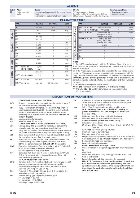
Label Alarm<br />
E1 Probe 1(control)<br />
faulty<br />
Controller - rE1 label<br />
Display - dIS label<br />
HC1<br />
Cause<br />
• measuring of values outside the nominal reading<br />
range<br />
• control probe faulty/shorted/open probe<br />
PAR. RANGE DEFAULT M.U.<br />
SP1 LS1...HS1 0.0 °C/°F<br />
H/C H/C* Flag<br />
dF1 0...30.0 1 °C/°F<br />
HS1 LS1...HdL * °C/°F<br />
LS1 LdL...HS1 * °C/°F<br />
dn1 0...250 1 sec<br />
do1<br />
0...250 0 min<br />
di1 0...250 0 min<br />
dE1 0...250 0 sec<br />
On1 0...250 0 min<br />
OF1 0...250 1 min<br />
LOC n/y n flag<br />
PA1 0...250<br />
0 num<br />
ndt <strong>IC</strong> <strong>912</strong> V-I n/y/int<br />
n num<br />
<strong>IC</strong> <strong>912</strong> <strong>Pt100</strong>-<strong>Tc</strong> n/y flag<br />
CA1<br />
-30.0...30.0 0.0 num<br />
dro** °C flag<br />
<strong>IC</strong> <strong>912</strong> <strong>Pt100</strong>-<strong>Tc</strong> °C/°F<br />
LdL*** <strong>IC</strong> <strong>912</strong> V-I -99.9...HdL 0*<br />
num<br />
HdL*** <strong>IC</strong> <strong>912</strong> V-I LdL...100 100/100.0/1000* num<br />
CONTROLLER (folder with “rE1” label)<br />
HC1 If set to H, the controller operates in heating mode. If set to C,<br />
the controller operates in cooling mode.<br />
dF1 Relay 1 intervention differential. The load will stop when Set<br />
point is reached (as indicated by the control probe) and will<br />
restart at a temperature equal to Set point plus (or minus<br />
depending on HC1) the value of the differential. See ON-OFF<br />
control diagram<br />
HS1 Maximum value for set point.<br />
LS1 Minimum value for set point.<br />
CONTROLLER <strong>PR</strong>OTECTIONS (folders with “rE1” label)<br />
dn1 Start-up delay. The specified time must elapse between the<br />
controller relay start-up request and actual start-up.<br />
do1 Delay after shut-down. The specified time must elapse between<br />
shut-down of the controller 1 relay and a subsequent start-up.<br />
di1 Delay between start-ups. Between two subsequent start-ups of<br />
the controller, the specified time must elapse.<br />
dE1 Shut-down delay. The specified time must elapse between the<br />
controller relay shut-down request and actual shut-down.<br />
NOTE: for parameters dn1, do1, di1, dE1 0= not active<br />
On1 Controller start-up time if probe is faulty. If set to “1” with Of1<br />
at “0” the controller is always on whereas if<br />
Of1>0 it operates in duty cycle mode.<br />
OF1 Controller shut-down time if probe is faulty. If set to “1” with<br />
On1 at “0” the controller is always off whereas if On1>0 it<br />
operates in duty cycle mode.<br />
DISPLAY (folder with “diS” label)<br />
LOC Keyboard locked (set point and buttons). However, you can still<br />
access the parameter programming menu and modify<br />
parameters including the status of this parameter to allow<br />
keyboard unlocking. y = yes; n = no.<br />
PA1 Password 1. When enabled (value is not 0) it represents the<br />
access key to level 1 parameters.<br />
ndt number display type.Display with decimal point.<br />
y = yes, range = -99...100<br />
n = no, range = -99,9...100.0<br />
int=integer, range = -990...1000<br />
ALARMS<br />
PARAMETER TABLE<br />
Effects<br />
“E1” label appears on display;<br />
Controller enabled as indicated by the On1 and<br />
OF1 parameters if programmed for the Duty Cycle<br />
Resolving problems<br />
• check the probe wiring<br />
• replace the probe<br />
<strong>IC</strong> <strong>912</strong> 2/4<br />
Configuration- CnF label<br />
Fpr<br />
PAR. RANGE DEFAULT M.U.<br />
H00 <strong>IC</strong> <strong>912</strong> V-I 420/020/010/05/01 *<br />
num<br />
(!)<br />
<strong>IC</strong> <strong>912</strong> <strong>Pt100</strong>-<strong>Tc</strong>(1) Pt1/JtC/HtC<br />
*<br />
num<br />
H03*** <strong>IC</strong> <strong>912</strong> V-I (ndt=n) -99...100<br />
(ndt=y) -99.0...100.0<br />
(ndt=int) -990...1000<br />
* num<br />
H04*** <strong>IC</strong> <strong>912</strong> V-I (ndt=n) -99...100<br />
(ndt=y) -99.0...100.0<br />
(ndt=int) -990...1000<br />
* num<br />
H10 0...250 0 min<br />
rEL / / /<br />
tAb / / /<br />
UL / / /<br />
dL / / /<br />
Fr (2) / / /<br />
NOTE:<br />
(1) The <strong>Pt100</strong> model only works with the <strong>Pt100</strong> input (3 wires) whereas<br />
<strong>Tc</strong>j/<strong>Tc</strong>K models, on the basis of this parameter, can work with the <strong>Tc</strong> input<br />
and the <strong>Pt100</strong> input.<br />
(2) If the Fr command is used, the data entered in the card will be permanently<br />
lost. This operation cannot be undone. After the operation with the<br />
Copy Card, the controller must be switched off and then switched back on<br />
WARNING(!) If one or more parameters marked with (!) are modified, the<br />
controller must be switched off after the modification and then switched<br />
back on<br />
* The default value depends on the model<br />
** The dro parameter is not present in <strong>IC</strong> <strong>912</strong> <strong>Pt100</strong>-<strong>Tc</strong> models<br />
*** The LdL, HdL, H03 and H04 parameters are only present in the<br />
<strong>IC</strong> <strong>912</strong> V-I models<br />
DESCRIPTION OF PARAMETERS<br />
CA1 Calibration 1. Positive or negative temperature value that is<br />
added to the value read by control probe (probe 1) before<br />
being displayed or used for control.<br />
dro Select °C or °F to display temperature read by probe.<br />
N. B.: switching from °C to °F DOES NOT modify set<br />
points, differentials, etc. (for example set point=10°C<br />
becomes 10°F).<br />
LdL Minimum value the instrument is able to display.<br />
HdL Maximum value the instrument is able to display.<br />
CONFIGURATION (folder with “CnF” label)<br />
H00 Selection of probe type.:<br />
<strong>IC</strong> <strong>912</strong> V-I: 420=1...20mA, 020=0...20mA, 010=0...10V, 05=0...5V,<br />
01=0...1V<br />
<strong>IC</strong> <strong>912</strong> <strong>Tc</strong>J: Pt1=<strong>Pt100</strong>, JtC=<strong>Tc</strong>j, HtC=<strong>Tc</strong>k<br />
H03 Minimum value of current input<br />
H04 Maximum value of current input<br />
H10 Output delay from power-on Attention! If = 0 is not active; if ≠<br />
0 the output will not be activated before this time has expired<br />
rEL Device version. Read only parameter.<br />
tAb Reserved. Read only parameter.<br />
COPY CARD (folder with “Fpr” label)<br />
UL UpLoad: transfer of programming parameters from instrument<br />
to<br />
Copy Card.<br />
dL downLoad: transfer of programming parameters from Copy<br />
Card to instrument.<br />
Fr Format. Cancelling all data entered in the copy card.<br />
N.B.: If “Fr” parameter (copy card formatting) is used, the<br />
data entered in the card will be permanently lost. This<br />
operation cannot be undone. After the operation with the<br />
Copy Card, the controller must be switched off and then<br />
switched back on