IC 912 Pt100 Tc / PR VI IV
IC 912 Pt100 Tc / PR VI IV
IC 912 Pt100 Tc / PR VI IV

Create successful ePaper yourself
Turn your PDF publications into a flip-book with our unique Google optimized e-Paper software.
cod. 9IS44018<br />
rel. 10/05 -GB-<br />
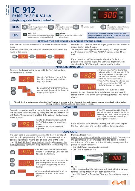
<strong>IC</strong> <strong>912</strong><br />
<strong>Pt100</strong> <strong>Tc</strong> / P R V-I I-V<br />
single stage electronic controller<br />
KEYS<br />
LEDs<br />
UP<br />
Scrolls through the menu items<br />
Increases the values<br />
Relay OUT<br />
ON for relay on (energized);blinking for<br />
delay, protection or enabling blocked.<br />
DOWN<br />
Scrolls through the menu items<br />
Decreases the values<br />
Allarme<br />
ON for active alarm; blinking for<br />
silenced alarm<br />
fnc<br />
ESC function (quit)<br />
SETTING THE SET POINT - MACHINE STATUS MENU<br />
Press the 'set' button and release it to access the machine status<br />
menu.<br />
In normal conditions, the labels for the two Set point values are<br />
found in the menu.<br />
set set<br />
To access the Programming menu, hold the “set” button down<br />
for more than 5 seconds.<br />
set<br />
Access to parameter handling can be limited by using a password.<br />
The password can be enabled by setting the PA1 parameter in the<br />
‘diS’ folder. The password is enabled if the value of the PA1 parameter<br />
is not 0.<br />
• To enter the Programming menu hold<br />
the “set” button down for more than 5<br />
set<br />
seconds.<br />
If specified, the PASSWORD will be<br />
requested<br />
set<br />
• When the ‘set’ button is pressed, the<br />
first folder in the menu is displayed.<br />
(e.g.: “rE1” folder)<br />
• By using the ‘UP’ and ‘DOWN’ buttons,<br />
you can scroll through all the folders in<br />
the programming menu<br />
The Copy Card is an accessory connected to the TTL serial port<br />
used for quick programming of the unit parameters (upload and<br />
download parameter map to one or more units of the same<br />
type). Upload (UL label), download (dL label) and copy card formatting<br />
(Fr label) operations are performed in the following way:<br />
set<br />
set<br />
set<br />
set<br />
• The ‘FPr’ folder contains the command<br />
needed to use the Copy Card. Press ‘set’<br />
to access the functions.<br />
• Use the ‘UP’ and ‘DOWN’ buttons to display<br />
the required function. Press the<br />
‘set’ to perform uploading (or downloading).<br />
• If the operation is successful 'y' will be<br />
displayed, if it is not, ‘n’ will be displayed.<br />
<strong>PR</strong>OGRAMMING MENU<br />
PASSWORD<br />
COPY CARD<br />
fnc set<br />
set<br />
Accesses the Set point and the Menus<br />
Confirms the commands<br />
Once the ‘SP1’ label has been displayed, press the “set” button to<br />
display the Set point 1 value.<br />
The Set point value appears on the display. To change the Set<br />
point value, use the “UP” and “DOWN” buttons within 15 seconds.<br />
If you press the “set” button again, when the fnc button is<br />
pressed or 15 seconds elapse, the last value displayed will be<br />
stored and the “SP1” label will reappear on the display.<br />
set<br />
set<br />
• By pressing the “set” button for the<br />
selected folder (in this example, ‘CnF’)<br />
the first parameter is displayed. Use<br />
the “UP” and “DOWN” buttons to<br />
select the required parameter.<br />
• Press “set” to display the selected parameter<br />
value and use the “UP” and<br />
“DOWN” buttons to change it.<br />
Once the “set” button has been<br />
pressed (or the 15 second time out elapses) the new value is<br />
stored and the label of the corresponding parameter will be displayed.<br />
set<br />
At start-up the instrument performs a Lamp Test for 5<br />
seconds. Afterwards, only for <strong>IC</strong> <strong>912</strong> <strong>Pt100</strong>, the label ‘Lod’<br />
(Loading) will appear for 10 seconds.<br />
At each level in both menus, when the “fnc” button is pressed or the 15 second time out elapses, you are taken back to the higher<br />
display level and the last value on the display is stored.<br />
• If the PA1 password is enabled (not 0)<br />
you will be asked to enter it. Do this by<br />
selecting the correct value using the UP<br />
and DOWN buttons and confirm by<br />
pressing the ‘set’ button.<br />
If the password is not entered correctly, the device will display<br />
the ‘PA1’ label again and the step will have to be repeated.<br />
Download from reset<br />
Connect the copy card when the instrument is OFF. The programming<br />
parameters are downloaded when the device is switched<br />
on. At the end of the lamp test, the following messages are displayed<br />
for about 5 seconds:<br />
• dLY label if copy operation is successful<br />
• DLn label if operation fails<br />
DOWNLOAD<br />
UPLOAD<br />
NOTE:<br />
• After downloading, the instrument will work with the parameter<br />
map settings that have just been downloaded.<br />
• see “FPr folder” in Parameter Table and Description of parameters
Label Alarm<br />
E1 Probe 1(control)<br />
faulty<br />
Controller - rE1 label<br />
Display - dIS label<br />
HC1<br />
Cause<br />
• measuring of values outside the nominal reading<br />
range<br />
• control probe faulty/shorted/open probe<br />
PAR. RANGE DEFAULT M.U.<br />
SP1 LS1...HS1 0.0 °C/°F<br />
H/C H/C* Flag<br />
dF1 0...30.0 1 °C/°F<br />
HS1 LS1...HdL * °C/°F<br />
LS1 LdL...HS1 * °C/°F<br />
dn1 0...250 1 sec<br />
do1<br />
0...250 0 min<br />
di1 0...250 0 min<br />
dE1 0...250 0 sec<br />
On1 0...250 0 min<br />
OF1 0...250 1 min<br />
LOC n/y n flag<br />
PA1 0...250<br />
0 num<br />
ndt <strong>IC</strong> <strong>912</strong> V-I n/y/int<br />
n num<br />
<strong>IC</strong> <strong>912</strong> <strong>Pt100</strong>-<strong>Tc</strong> n/y flag<br />
CA1<br />
-30.0...30.0 0.0 num<br />
dro** °C flag<br />
<strong>IC</strong> <strong>912</strong> <strong>Pt100</strong>-<strong>Tc</strong> °C/°F<br />
LdL*** <strong>IC</strong> <strong>912</strong> V-I -99.9...HdL 0*<br />
num<br />
HdL*** <strong>IC</strong> <strong>912</strong> V-I LdL...100 100/100.0/1000* num<br />
CONTROLLER (folder with “rE1” label)<br />
HC1 If set to H, the controller operates in heating mode. If set to C,<br />
the controller operates in cooling mode.<br />
dF1 Relay 1 intervention differential. The load will stop when Set<br />
point is reached (as indicated by the control probe) and will<br />
restart at a temperature equal to Set point plus (or minus<br />
depending on HC1) the value of the differential. See ON-OFF<br />
control diagram<br />
HS1 Maximum value for set point.<br />
LS1 Minimum value for set point.<br />
CONTROLLER <strong>PR</strong>OTECTIONS (folders with “rE1” label)<br />
dn1 Start-up delay. The specified time must elapse between the<br />
controller relay start-up request and actual start-up.<br />
do1 Delay after shut-down. The specified time must elapse between<br />
shut-down of the controller 1 relay and a subsequent start-up.<br />
di1 Delay between start-ups. Between two subsequent start-ups of<br />
the controller, the specified time must elapse.<br />
dE1 Shut-down delay. The specified time must elapse between the<br />
controller relay shut-down request and actual shut-down.<br />
NOTE: for parameters dn1, do1, di1, dE1 0= not active<br />
On1 Controller start-up time if probe is faulty. If set to “1” with Of1<br />
at “0” the controller is always on whereas if<br />
Of1>0 it operates in duty cycle mode.<br />
OF1 Controller shut-down time if probe is faulty. If set to “1” with<br />
On1 at “0” the controller is always off whereas if On1>0 it<br />
operates in duty cycle mode.<br />
DISPLAY (folder with “diS” label)<br />
LOC Keyboard locked (set point and buttons). However, you can still<br />
access the parameter programming menu and modify<br />
parameters including the status of this parameter to allow<br />
keyboard unlocking. y = yes; n = no.<br />
PA1 Password 1. When enabled (value is not 0) it represents the<br />
access key to level 1 parameters.<br />
ndt number display type.Display with decimal point.<br />
y = yes, range = -99...100<br />
n = no, range = -99,9...100.0<br />
int=integer, range = -990...1000<br />
ALARMS<br />
PARAMETER TABLE<br />
Effects<br />
“E1” label appears on display;<br />
Controller enabled as indicated by the On1 and<br />
OF1 parameters if programmed for the Duty Cycle<br />
Resolving problems<br />
• check the probe wiring<br />
• replace the probe<br />
<strong>IC</strong> <strong>912</strong> 2/4<br />
Configuration- CnF label<br />
Fpr<br />
PAR. RANGE DEFAULT M.U.<br />
H00 <strong>IC</strong> <strong>912</strong> V-I 420/020/010/05/01 *<br />
num<br />
(!)<br />
<strong>IC</strong> <strong>912</strong> <strong>Pt100</strong>-<strong>Tc</strong>(1) Pt1/JtC/HtC<br />
*<br />
num<br />
H03*** <strong>IC</strong> <strong>912</strong> V-I (ndt=n) -99...100<br />
(ndt=y) -99.0...100.0<br />
(ndt=int) -990...1000<br />
* num<br />
H04*** <strong>IC</strong> <strong>912</strong> V-I (ndt=n) -99...100<br />
(ndt=y) -99.0...100.0<br />
(ndt=int) -990...1000<br />
* num<br />
H10 0...250 0 min<br />
rEL / / /<br />
tAb / / /<br />
UL / / /<br />
dL / / /<br />
Fr (2) / / /<br />
NOTE:<br />
(1) The <strong>Pt100</strong> model only works with the <strong>Pt100</strong> input (3 wires) whereas<br />
<strong>Tc</strong>j/<strong>Tc</strong>K models, on the basis of this parameter, can work with the <strong>Tc</strong> input<br />
and the <strong>Pt100</strong> input.<br />
(2) If the Fr command is used, the data entered in the card will be permanently<br />
lost. This operation cannot be undone. After the operation with the<br />
Copy Card, the controller must be switched off and then switched back on<br />
WARNING(!) If one or more parameters marked with (!) are modified, the<br />
controller must be switched off after the modification and then switched<br />
back on<br />
* The default value depends on the model<br />
** The dro parameter is not present in <strong>IC</strong> <strong>912</strong> <strong>Pt100</strong>-<strong>Tc</strong> models<br />
*** The LdL, HdL, H03 and H04 parameters are only present in the<br />
<strong>IC</strong> <strong>912</strong> V-I models<br />
DESCRIPTION OF PARAMETERS<br />
CA1 Calibration 1. Positive or negative temperature value that is<br />
added to the value read by control probe (probe 1) before<br />
being displayed or used for control.<br />
dro Select °C or °F to display temperature read by probe.<br />
N. B.: switching from °C to °F DOES NOT modify set<br />
points, differentials, etc. (for example set point=10°C<br />
becomes 10°F).<br />
LdL Minimum value the instrument is able to display.<br />
HdL Maximum value the instrument is able to display.<br />
CONFIGURATION (folder with “CnF” label)<br />
H00 Selection of probe type.:<br />
<strong>IC</strong> <strong>912</strong> V-I: 420=1...20mA, 020=0...20mA, 010=0...10V, 05=0...5V,<br />
01=0...1V<br />
<strong>IC</strong> <strong>912</strong> <strong>Tc</strong>J: Pt1=<strong>Pt100</strong>, JtC=<strong>Tc</strong>j, HtC=<strong>Tc</strong>k<br />
H03 Minimum value of current input<br />
H04 Maximum value of current input<br />
H10 Output delay from power-on Attention! If = 0 is not active; if ≠<br />
0 the output will not be activated before this time has expired<br />
rEL Device version. Read only parameter.<br />
tAb Reserved. Read only parameter.<br />
COPY CARD (folder with “Fpr” label)<br />
UL UpLoad: transfer of programming parameters from instrument<br />
to<br />
Copy Card.<br />
dL downLoad: transfer of programming parameters from Copy<br />
Card to instrument.<br />
Fr Format. Cancelling all data entered in the copy card.<br />
N.B.: If “Fr” parameter (copy card formatting) is used, the<br />
data entered in the card will be permanently lost. This<br />
operation cannot be undone. After the operation with the<br />
Copy Card, the controller must be switched off and then<br />
switched back on
TECHN<strong>IC</strong>AL DATA <strong>IC</strong> <strong>912</strong> P/R/V-I/I-V <strong>IC</strong> <strong>912</strong> <strong>Pt100</strong>/TC<br />
Front protection<br />
Casing<br />
Dimensions<br />
Mounting<br />
Operating temperature<br />
Storage temperature<br />
Usage and storage<br />
ambient humidity<br />
Display range<br />
Analogue input<br />
Serial<br />
Digital ouputs<br />
Buzzer output<br />
Measurement range<br />
Accuracy<br />
Resolution<br />
Consumption<br />
Power supply<br />
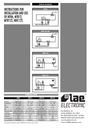
WIRING DIAGRAMS<br />
On<br />
IP65<br />
resin plastic casing PC+ABS UL94 V-0, polycarbonate<br />
front polycarbonate front, thermoplastic resin buttons<br />
front panel 74x32 mm, depth 59mm (terminals excluded)<br />
panel-mounted with drilling template 71x29mm (+0.2/-0.1 mm)<br />
-5°C...55°C<br />
-30°C...85°C<br />
10...90% RH (non-condensing)<br />
-99...100 (ndt=n), -99,9...100,0 (ndt=y), -999...1000 (ndt=int)<br />
on display 3 1/2 digits plus sign<br />
1 V-I (0-1V, 0-5V, 0-10V, 0-20...mA, 4...20mA par.H00)<br />
TTL for Copy Card connection<br />
1 SPST relay 8(3)A 1/2 hp 250 Va<br />
only in some models<br />
from -999 to 1000<br />
better than 0.5% of full scale + 1 digit.<br />
1 or 0.1 digits depending on parameter settings<br />
1,5 W max(mod. 12V) / 3 VA max (mod. 230V)<br />
12Va/c, 12/24 Va/c, 24Va/c 10%,<br />
110/115Va, 220/230 Va 10% 50/60 Hz<br />
<strong>IC</strong> <strong>912</strong> P/R/<strong>VI</strong> - 12 V<br />
1 2 3<br />
<strong>IC</strong> <strong>912</strong> P/R/<strong>VI</strong> - 230 V<br />
1 2 3 6 7<br />
Supply<br />
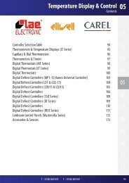
ON-OFF CONTROL DIAGRAM<br />
HC1 Heat/Cool Mode<br />
SP1 Setpoint 1<br />
dF1 Relay 1 tripping differential.<br />
HC1=H<br />
dF1<br />
SP1-dF1<br />
SP1<br />
Off<br />
6 7 8 9 10 11<br />
Supply<br />
8 9 10 11<br />
1-2 N.A. controller relay OUT<br />
1-3 N.C. controller relay OUT<br />
6-7 Power supply<br />
8-9-11 Voltage input (8=ground; 9=signal; =12V)<br />
8-10-11 Voltage input (8=ground; 9=signal; =12V)<br />
A TTL input for Copy Card<br />
MECHAN<strong>IC</strong>AL ASSEMBLY<br />
The unit has been designed for panel-mounting: Drill a 29x71 mm hole, insert a tool and<br />
fix it in place with the brackets provided. Do not assemble the instrument in excessively<br />
humid or dirty locations since it is designed to be used in locations with normal levels of<br />
pollution.<br />
Always make sure that the area next to the cooling openings of the tool is adequately<br />
ventilated.<br />
Off<br />
SP1<br />
dF1<br />
HC1=C<br />
SP1+dF1<br />
•<br />
•<br />
V<br />
I<br />
On<br />
V<br />
I<br />
•<br />
•<br />
•<br />
•<br />
+12V<br />
+12V<br />
A<br />
A<br />
IP65<br />
resin plastic casing PC+ABS UL94 V-0, polycarbonate<br />
front polycarbonate front, thermoplastic resin buttons<br />
front panel 74x32 mm, depth 59mm (terminals excluded)a<br />
panel-mounted with drilling template 71x29mm (+0.2/-0.1 mm)<br />
-5°C...55°C<br />
-30°C...85°C<br />
10...90% RH (non-condensing)<br />
<strong>Pt100</strong>: -150...650°C / <strong>Tc</strong>J: -40...750°C / <strong>Tc</strong>K: -40...1350°C*<br />
on display 3 1/2 digits plus sign<br />
1 <strong>Pt100</strong> or 1 <strong>Tc</strong>J or <strong>Tc</strong>K (depending on model)<br />
TTL for Copy Card connection<br />
1 SPST relay 8(3)A 1/2 hp 250 Va<br />
only in some models<br />
from -150 to 1350<br />
see “<strong>Pt100</strong>/<strong>Tc</strong>J/<strong>Tc</strong>K models” table<br />
see “<strong>Pt100</strong>/<strong>Tc</strong>J/<strong>Tc</strong>K models” table<br />
1,5 W max(mod. 12V) / 3 VA max (mod. 230V)<br />
12Va/c, 12/24 Va/c, 24Va/c 10%,<br />
110/115Va, 220/230 Va 10% 50/60 Hz<br />
<strong>IC</strong> <strong>912</strong> <strong>Pt100</strong>/TC - 12 V<br />
1 2 3<br />
<strong>IC</strong> <strong>912</strong> <strong>Pt100</strong>/TC - 230 V<br />
1 2 3 6 7<br />
6 7 10 11 12<br />
Supply<br />
+ -<br />
10 11 12<br />
1-2<br />
Supply<br />
N.A. controller relay OUT<br />
+ -<br />
1-3 N.C. controller relay OUT<br />
6-7 Power supply<br />
10-11-12 Probe input <strong>Pt100</strong> 3 wires Pb1<br />
11-12 <strong>Tc</strong>J/<strong>Tc</strong>K input (11= + ; 12= - )<br />
A TTL input for Copy Card<br />
<strong>Pt100</strong>/ <strong>Tc</strong>J/ <strong>Tc</strong>K MODELS<br />
<strong>Pt100</strong>:<br />
Accuracy:<br />
0,5% for full scale value + 1 digit;<br />
0.2% from -150 to 300°C<br />
Resolution:<br />
0.1°C (0.1°F) up to 199.9°C; 1°F over<br />
<strong>Tc</strong>J:<br />
Accuracy:<br />
0.4% for full scale value + 1 digit;<br />
Resolution:<br />
0.1°C (0.1°F) up to 199.9°C; 1°F over<br />
<strong>Tc</strong>K:<br />
Accuracy:<br />
0,5% for full scale value + 1 digit;<br />
0.3% from -40 to 800°C<br />
Resolution:<br />
1°C (1°F)<br />
The technical characteristics in this document concerning<br />
measurements (range, accuracy, resolution, etc.) refer to<br />
the instrument in the strictest sense and not to any accessories<br />
provided such as probes, for example. This means, for<br />
example, that an error introduced by the probe is added to<br />
any error that is typical of the instrument.<br />
<strong>IC</strong> <strong>912</strong> 3/4<br />
A<br />
A
ELECTR<strong>IC</strong>AL CONNECTIONS<br />
Caution! Always switch off machine before working on electrical connections. The instrument has screw terminals for connecting electrical cables<br />
with a maximum diameter of 2.5 mm 2 (only one conductor per terminal for power connections): for terminal capacity, see instrument label.The relay<br />
contacts are voltage-free. Do not exceed the maximum current allowed. For higher loads, use a suitable contactor. Make sure that the power voltage<br />
complies with the device voltage. The sensor has no connection polarity and can be extended using an ordinary bipolar cable (note that extending the<br />
probe may affect the electromagnetic compatibility (EMC) of the instrument: special care must be used when wiring). Probe cables, power supply<br />
cables and the TTL serial cable should be kept separate from power cables.<br />
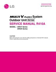
EWHS 280 2 wires<br />
8 9 10 11<br />
EWPA 007/030 2 wires / Transducer<br />
8 9 10 11<br />
white<br />
EWHS 300/310 3 wires<br />
8 9 10 11<br />
Eliwell & Controlli s.r.l.<br />
Via dell'Industria, 15 Zona Industriale Paludi<br />
32010 Pieve d'Alpago (BL) ITALY<br />
Telephone +39 0437 986111<br />
Facsimile +39 0437 989066<br />
Internet http://www.eliwell.it<br />
Technical Customer Support:<br />
Telephone +39 0437 986300<br />
Email: techsuppeliwell@invensys.com<br />
Invensys Controls Europe<br />
An Invensys Company<br />
blue<br />
V+<br />
RH/T<br />
GND (only EWHS310)<br />
brown<br />
CONDITIONS OF USE<br />
brown<br />
CONFIGURATION OF EWPA-EWHS <strong>PR</strong>OBES<br />
Transducer<br />
Probe<br />
Probe<br />
EWHS 310 4 wires<br />
cod.9IS44018<br />
10-05 GB<br />
<strong>IC</strong> <strong>912</strong> 4/4<br />
<strong>IC</strong> 915 V-I<br />
GND<br />
RH<br />
V+<br />
GND<br />
<strong>IC</strong> 915 V-I<br />
8 9 10 11 8 9 10 11<br />
PERMITTED USE<br />
For safety reasons the instrument must be installed and used in accordance with the instructions supplied. Users must not be able to access parts with dangerous voltage levels<br />
under normal operating conditions.<br />
The device must be suitably protected from water and dust according to the specific application and only be accessible using special tools (except for the front keypad).<br />
The device can be fitted to equipment for household use and/or similar use in the refrigeration sector and has been tested with regard to safety in accordance with the<br />
European harmonized reference standards: It is classified as follows:<br />
• as an automatic electronic control device to be integrated as regards its construction;<br />
• as a 1 B type operated control device as regards its automatic operating features;<br />
• as a Class A device in relation to the category and structure of the software.<br />
UNPERMITTED USE<br />
The use of the unit for applications other than those described above is forbidden.<br />
It should be noted that the relay contacts supplied with the device are functional and therefore exposed to potential faults. Any protection devices required to comply with<br />
product requirements or dictated by common sense due to obvious safety reasons should be installed externally.<br />
DISCLAIMER<br />
This document is exclusive property of Eliwell and cannot be reproduced<br />
and circulated unless expressly authorized by Eliwell. Although Eliwell<br />
has taken all possible measures to guarantee the accuracy of this document,<br />
it declines any responsibility for any damage arising out of its use.<br />
The same applies to any person or company involved in preparing and<br />
writing this document. Eliwell reserves the right to make any changes or<br />
improvements without prior notice and at any time.<br />
T<br />
RESPONSIBILITY AND RESIDUAL RISKS<br />
Eliwell shall not be liable for any damages deriving from:<br />
- installation/use other than that prescribed and, in particular, which does<br />
not comply with the safety standards specified in the regulations and/or<br />
those given herein;<br />
- use on boards which do not guarantee proper protection against electric<br />
shock, water or dust when assembled;<br />
- use on boards which allow dangerous parts to be accessed without the use<br />
of tools;<br />
- tampering with and/or alteration of the product;<br />
- installation/use on boards that do not comply with the standards and regulations<br />
in force.<br />
Probe