Best Practices Trackside Tower and Antenna Installation - Railroad ...
Best Practices Trackside Tower and Antenna Installation - Railroad ...
Best Practices Trackside Tower and Antenna Installation - Railroad ...

You also want an ePaper? Increase the reach of your titles
YUMPU automatically turns print PDFs into web optimized ePapers that Google loves.
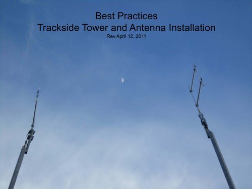
<strong>Best</strong> <strong>Practices</strong><br />
<strong>Trackside</strong> <strong>Tower</strong> <strong>and</strong> <strong>Antenna</strong> <strong>Installation</strong><br />
Rev April 12, 2011
PTC <strong>and</strong> ARES <strong>Antenna</strong><br />
<strong>Tower</strong>s<br />
•Maximum distance from building<br />
is 25 feet<br />
Separation between<br />
<strong>Antenna</strong>s<br />
•Prefer 25 feet<br />
•Minimum 10 feet, if less than<br />
10ft a160/200 MHZ filter is<br />
required<br />
Turn base so when tower is<br />
tipped down antenna will be<br />
in a flat spot.
Make sure you know<br />
the conversion from<br />
PSI to Foot Pounds for<br />
the machine you are<br />
operating.<br />
The drilled pier foundation is designed to minimize soil disturbance <strong>and</strong> time involved for installation compared to<br />
other types of foundations. The minimum requirements for properly installed helical pier are 1) to achieve<br />
penetration so the pier’s top base plate is 8” or less above grade <strong>and</strong> 2) achieve a minimum torque value of 3,000<br />
foot-pounds. A maximum torque value of 15,000 foot-pounds should be used. In the event the helical pier<br />
foundations cannot be installed per the st<strong>and</strong>ard procedure above, one of the following Alternative Procedures<br />
should be used. (See EMI Helical Pier <strong>Installation</strong> <strong>and</strong> Maintenance Instructions)
Backfill the helical pier<br />
then cap with premix<br />
concrete.
Grind area for cadweld<br />
<strong>Tower</strong> Base Grounding
Attach mold to tower using<br />
clamp. This mold is designed to<br />
do the cadweld while the tower<br />
base is st<strong>and</strong>ing.<br />
ERICO Cadweld Parts<br />
Mold & H<strong>and</strong>le<br />
L160 H<strong>and</strong>le Clamp<br />
VBC-1G mold used to attach #6<br />
solid copper to base of tower<br />
B134 Vertical Surface Mold<br />
Support C-clamp<br />
#65 shot comes in boxes of 20<br />
Mold & slag cleaning<br />
T394 Mold cleaning brush<br />
B-136-A Slag removal spade<br />
Mold Sealer<br />
T403 Mold sealer when mold<br />
starts to wear
Spray cadweld <strong>and</strong> tower with<br />
cold galvanize covering area<br />
where the galvanize was<br />
removed.<br />
DO NOT USE SIGNAL GRAY<br />
SPRAY PAINT!!!
Ground Rods<br />
Ground rods at tower should be a minimum of 24”<br />
below top of soil. If frost line is deeper than 24” prefer<br />
you to go deeper. Ground wire <strong>and</strong> conduit can be ran<br />
in same trench.<br />
Conduit (liquid tight) should be the same depth.
Halo around helical pier <strong>and</strong> ground wire running to building<br />
halo
While backfilling compact soil using<br />
tamper.<br />
http://www.astm.org/SEARCH/sites<br />
earch.html?query=soil+compact
12”<br />
Completed Helical Pier <strong>and</strong> <strong>Tower</strong> Base Install
Operational Procedure<br />
Acceptance Criteria<br />
(OPAC)<br />
Resistance to ground at<br />
tower ring 5 Ohms (less than)<br />
Current flow to ground at<br />
tower ring (Amps) .2 amps<br />
(less than)<br />
Resistance to ground at<br />
building ring (Ohms) 5 ohms<br />
all legs (less than)<br />
Current flow to ground at<br />
building ring (Amps) all legs<br />
.2 amps (less than)
Mid span tool for removing sheathing from LMR600 coax for the ground connection<br />
Part # GST-600A
Ground Clamp<br />
• Strip sheathing off LMR600 coax<br />
• Attach ground kit with pigtail to<br />
right side of coax<br />
• Apply mastic by wrapping from<br />
bottom of ground clamp to top<br />
• Wrap with vinyl tape; start wrap<br />
at bottom of clamp, wrap to top<br />
then down, then last wrap should<br />
be bottom to top to create<br />
shingle effect. Same procedure<br />
for the top of the tower.
Dual Mechanical<br />
Ground Tab<br />
• Grind galvanize off tab for<br />
ground connection<br />
• Measure ground wire; gradual<br />
curve to tab.<br />
• Slide heat shrink on wire, crimp<br />
on ground lug. Heat the heat<br />
shrink after you crimp on the lug<br />
or after lug is attached to the<br />
ground tab.<br />
• Put oxidation grease on ground<br />
tab then attach lug to tab.<br />
• Spray cold galvanize on lug <strong>and</strong><br />
tab<br />
• DO NOT USE SIGNAL GRAY<br />
SPRAY PAINT!!!
Coax Ground at Base of <strong>Tower</strong>: Both are acceptable curves for the ground wire going to the ground tab on the<br />
tower.<br />
Right picture is missing the cold galvanize spray.
Installer put the oxidation grease on<br />
the dual mechanical tab <strong>and</strong> is<br />
measuring the ground<br />
wire length.
PTC Latest Mods for Top of <strong>Tower</strong><br />
� 6 inch pigtail coming from PTC antenna<br />
� 5/8 coax 12” to 18” maintenance loop<br />
� Green Identification tape on PTC antenna
Tape bottom of hoisting grip
Ground lug will be at this angle.<br />
You can use either hole on tab.<br />
Break the first hole off lug, you<br />
can see the indention where break<br />
will occur<br />
Don’t forget the heat shrink
Grind galvanize off ground tab. Grind<br />
only the hole you will be using.<br />
Apply oxidation grease<br />
Connect lug<br />
Spray cold galvanize on lug <strong>and</strong> ground<br />
tab.<br />
Ground wire should be<br />
shortest distance from ground<br />
clamp to tower ground tab.<br />
Wire should be straight or<br />
slight curve.
Example of a completed ground connection at the top of the tower
Ground will be attached at these points<br />
Single loop:<br />
LMR600 comes out of<br />
tower <strong>and</strong> is coiled going<br />
clockwise.<br />
6ft pigtail on the antenna<br />
goes counter clockwise<br />
<strong>and</strong> connectors meet in<br />
the middle next to the<br />
mounting pipe.
<strong>Antenna</strong> will point towards track when tower is raised.<br />
Mount bracket clamp at<br />
least 2” below top of pipe
If no hook is provided, attach the grip to the bottom U-bolt of the antenna mast.
New Building for Control Point<br />
Cut wood out next to rack so you can drill<br />
holes through the floor for the liquid tight<br />
entering the building<br />
See signal engineering drawing for location.<br />
See next slide
Wood removed, holes drilled, liquid<br />
tight connected to the floor <strong>and</strong> coax<br />
ran into building.<br />
Buildings will start coming with holes<br />
drilled <strong>and</strong> a bracket mounted for<br />
polyphasers.
Completed install With:<br />
Weather Caps<br />
8” st<strong>and</strong>offs<br />
Polyphasers<br />
The floor is the ground plane so<br />
ground wire is not needed.<br />
PTC coax is ran closest to<br />
board.<br />
PTC<br />
ARES or ATCS
New Building for<br />
an Intermediate
Use self tapping screws to<br />
fasten plate to floor
Operational Procedure<br />
Acceptance Criteria<br />
(OPAC)
VIC 100 GPS <strong>Antenna</strong> <strong>and</strong> Bracket
Ground wire is not needed when<br />
bracket is attached to a metal building.<br />
The building provides the ground<br />
plane.
Mark IV GPS <strong>Antenna</strong> <strong>and</strong> Bracket