PTM-A PTM-A FLOOR MOUNTING SINGLE SPRING ... - TOZEN
PTM-A PTM-A FLOOR MOUNTING SINGLE SPRING ... - TOZEN
PTM-A PTM-A FLOOR MOUNTING SINGLE SPRING ... - TOZEN

Create successful ePaper yourself
Turn your PDF publications into a flip-book with our unique Google optimized e-Paper software.
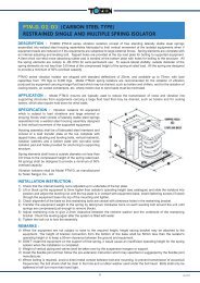
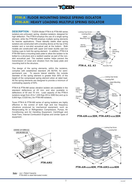
<strong>PTM</strong>-A <strong>FLOOR</strong> <strong>MOUNTING</strong> <strong>SINGLE</strong> <strong>SPRING</strong> ISOLATOR<br />
<strong>PTM</strong>-AM HEAVY LOADING MULTIPLE <strong>SPRING</strong> ISOLATOR<br />
DESCRIPTION : <strong>TOZEN</strong> Model <strong>PTM</strong>-A & <strong>PTM</strong>-AM series<br />
isolators are unhoused, spring, vibration isolators, designed for<br />
high deflection. The <strong>PTM</strong>-A employs the use of a single spring<br />
element, while the <strong>PTM</strong>-AM employs multiple spring elements<br />
for heavier applications. These laterally stable steel spring<br />
isolators are constructed with a leveling device at the top of the<br />
isolator and a non-skid acoustical pad at the bottom. Both<br />
models are constructed with upper and lower ductile cast iron<br />
holding cups to hold the spring element. In addition, <strong>PTM</strong>-A &<br />
<strong>PTM</strong>-AM have a mounting base plate to allow the isolator to be<br />
bolted to a structure and a resilient washer as part of the nonskid<br />
acoustical pad. The resilient washer helps prevent the<br />
transmission of noise and vibration from the base plate and<br />
mounting bolt to the structure.<br />
The design of the spring elements, within the isolators,<br />
complies with established standard JIS B2704, for semipermanent<br />
use. To assure lateral stability, the outside<br />
diameter of the spring element is greater than 80% of the<br />
height of the compressed spring element when at rated load.<br />
All the spring elements are designed to provide a minimum of<br />
overloading capacity of 50%.<br />
<strong>PTM</strong>-A & <strong>PTM</strong>-AM series vibration isolator are available in the<br />
standard deflections at 25 mm, and also available in<br />
deflections of 50 and 75 mm. Load capacity of the <strong>PTM</strong>-A<br />
isolators range from 25 to 1,400 Kgs (55 to 3080 lbs) and up to<br />
5,600 Kgs (12320 lbs.) for <strong>PTM</strong>-AM isolators.<br />
Tozen <strong>PTM</strong>-A & <strong>PTM</strong>-AM series of spring isolators are highly<br />
effective in the control of both high and low frequency<br />
vibrations produced by mechanical equipment, such as<br />
Reciprocating Air or Refrigeration Compressors, Pumps, Air<br />
Conditioning and Air Handling Equipment, Centrifugal and<br />
Axial Fans, Internal Combustion Engines and similar types of<br />
equipment.<br />
<strong>PTM</strong>-AM3<br />
Note : xxx = Rated Capacity<br />
<strong>PTM</strong>-AM3 is steel fabricated model.<br />
3<br />
<strong>PTM</strong>-A, A2, A3<br />
<strong>PTM</strong>-AM-xxx2EM, <strong>PTM</strong>-AM2-xxx2EM<br />
<strong>PTM</strong>-AM-xxx4EM, <strong>PTM</strong>-AM2-xxx4EM<br />
VI-0107
APPLICATION : <strong>PTM</strong>-A & <strong>PTM</strong>-AM series spring isolators are recommended for use in isolating floor mounted sources<br />
of noise and vibration located near critical quiet areas.<br />
<strong>PTM</strong>-A series spring isolators are typically used to reduce the transmission of noise and vibration from low speed<br />
mechanical equipment into a building structure.<br />
<strong>PTM</strong>-A & AM series spring isolators can be used in a wide range of applications involving the isolation of mechanical<br />
equipment, such as Reciprocating Air or Refrigeration Compressors, Close Coupled and Base Mounted Pumps, Package Air<br />
Handling and Refrigeration Equipment, Centrifugal Fans, Internal Combustion Engines and similar equipment.<br />
SPECIFICATION :<br />
The vibration isolators shall be free standing, with laterally stable steel spring elements, without housings, snubbers or<br />
guides. The isolators shall be constructed with the ductile cast iron upper mounting cup and the ductile cast iron lower<br />
mounting cup to hold the spring element, and a non-skid acoustical pad is attached under the lower cup. The isolators shall<br />
be provided with an adjusting bolt, cap screw and washer in top of the isolator for leveling and attachment to the equipment.<br />
The spring elements of the isolator shall have an outside diameter greater than 80% of the height of the compressed spring<br />
element at rated load. All spring elements shall be designed to provide a minimum overloading capacity of 50%.<br />
The isolators shall be selected to provide operating static deflection shown on the Vibration Isolation Schedule or as<br />
indicated by the project specifications. Isolators shall be color coded or otherwise identified to indicate load capacity.<br />
<strong>PTM</strong>-A, AM<br />
TYPE 25 mm. DEFLECTION <strong>SINGLE</strong> & MULTIPLE <strong>SPRING</strong> VIBRATION ISOLATOR<br />
MODEL<br />
RATED<br />
CAPACITY<br />
<strong>SPRING</strong><br />
CONSTANT<br />
(kgs) (Lbs) (kg/mm)<br />
<strong>SPRING</strong> ELEMENT<br />
<strong>SPRING</strong><br />
COLOR<br />
<strong>PTM</strong>-A-25S 25 55 1.0 WHITE<br />
<strong>PTM</strong>-A-35S 35 77 1.4 YELLOW<br />
<strong>PTM</strong>-A-50S 50 110 2.0 ORANGE<br />
<strong>PTM</strong>-A-80S 80 176 3.2 VIOLET<br />
<strong>PTM</strong>-A-120S 120 264 4.8 RED<br />
<strong>PTM</strong>-A-175ES 175 385 7.0 SILVER<br />
<strong>PTM</strong>-A-225ES 225 495 9.0 BROWN<br />
<strong>PTM</strong>-A-200M 200 440 8.0 VIOLET<br />
<strong>PTM</strong>-A-300M 300 660 12.0 RED<br />
<strong>PTM</strong>-A-450M 450 990 18.0 GREEN<br />
<strong>PTM</strong>-A-600EM 600 1320 24.0 SILVER<br />
<strong>PTM</strong>-A-825EM 825 1815 33.0 BROWN<br />
<strong>PTM</strong>-A-1100EM 1100 2420 44.0 BLUE<br />
<strong>PTM</strong>-A-1400EM 1400 3080 56.0 BLUE+BROWN<br />
<strong>PTM</strong>-AM-1652EM 1650 3630 66.0 BROWN<br />
<strong>PTM</strong>-AM-2202EM 2200 4840 88.0 BLUE<br />
<strong>PTM</strong>-AM-2802EM 2800 6160 112.0 BLUE+BROWN<br />
<strong>PTM</strong>-AM-3304EM 3300 7260 132.0 BROWN<br />
<strong>PTM</strong>-AM-4404EM 4400 9680 176.0 BLUE<br />
<strong>PTM</strong>-AM-5604EM 5600 12320 224.0 BLUE+BROWN<br />
OD<br />
(mm)<br />
FREE<br />
HEIGHT<br />
(mm)<br />
OPERATING<br />
HEIGHT<br />
(H)<br />
DIMENSION (mm) LOCKING<br />
CAP<br />
A B C D<br />
SCREW<br />
(LS)<br />
LEVELING<br />
BOLT<br />
(LB)<br />
50 80 120 61 107 89 10 M10x32 M16x70<br />
75 100 150 88 136 117 13 M12x43<br />
M22x80<br />
75 100 144 112 198 75 14x18 M12x43 M22x80<br />
75 100 152 197 197 161 14x18 M16x45 M30x90<br />
NOTE-1: All springs are laterally stable and suitable for free standing application. (Outside diameter > 80% of defection height)<br />
NOTE-2: All springs are designed with additional travel to solid at least 50% of rated load.<br />
NOTE-3: Please refer to relevant brochure or our technical division for greater deflection and loading.<br />
4<br />
VI-0107
<strong>PTM</strong>-A2, AM2<br />
TYPE 50 mm. DEFLECTION <strong>SINGLE</strong> & MULTIPLE <strong>SPRING</strong> VIBRATION ISOLATOR<br />
MODEL<br />
RATED<br />
CAPACITY <strong>SPRING</strong><br />
CONSTANT<br />
(kgs) (Lbs) (kg/mm)<br />
<strong>SPRING</strong> ELEMENT OPERAT-<br />
<strong>SPRING</strong><br />
COLOR<br />
<strong>PTM</strong>-A2-25S 25 55 0.5 WHITE<br />
<strong>PTM</strong>-A2-35S 35 77 0.7 YELLOW<br />
<strong>PTM</strong>-A2-50S 50 110 1.0 ORANGE<br />
<strong>PTM</strong>-A2-80ES 80 176 1.6 VIOLET<br />
<strong>PTM</strong>-A2-125ES 125 275 2.5 RED<br />
<strong>PTM</strong>-A2-175ES 175 385 3.5 SILVER<br />
<strong>PTM</strong>-A2-250ES 250 550 5.0 BROWN<br />
<strong>PTM</strong>-A2-175EM 175 385 3.5 ORANGE<br />
<strong>PTM</strong>-A2-245EM 245 539 4.9 VIOLET<br />
<strong>PTM</strong>-A2-350EM 350 770 7.0 RED<br />
<strong>PTM</strong>-A2-525EM 525 1155 10.5 GREEN<br />
<strong>PTM</strong>-A2-750EM 750 1650 15.0 SILVER<br />
<strong>PTM</strong>-A2-1050EM 1050 2310 21.0 SILVER+BROWN<br />
<strong>PTM</strong>-AM2-1502EM 1500 3300 30.0 SILVER<br />
<strong>PTM</strong>-AM2-2102EM 2100 4620 42.0 SILVER+BROWN<br />
<strong>PTM</strong>-AM2-3004EM 3000 6600 60.0 SILVER<br />
<strong>PTM</strong>-AM2-4204EM 4200 9240 84.0 SILVER+BROWN<br />
MODEL<br />
RATED<br />
CAPACITY <strong>SPRING</strong><br />
CONSTANT<br />
(kgs) (Lbs) (kg/mm)<br />
OD<br />
(mm)<br />
5<br />
FREE<br />
HEIGHT<br />
(mm)<br />
ING<br />
HEIGHT<br />
(H)<br />
DIMENSION (mm) LOCKING<br />
CAP<br />
A B C D<br />
SCREW<br />
(LS)<br />
LEVELING<br />
BOLT<br />
(LB)<br />
75 120 170 88 136 117 13 M12x43 M22x80<br />
90 145 195 101 155 130 13 M12x43 M22x115<br />
90 145<br />
<strong>SPRING</strong> ELEMENT OPERAT-<br />
189 130 230 92 14x18 M12x43 M22x80<br />
196 244 244 203 14x18 M16x45<br />
NOTE-1: All springs are laterally stable and suitable for free standing application. (Outside diameter > 80% of defection height)<br />
NOTE-2: All springs are designed with additional travel to solid at least 50% of rated load.<br />
NOTE-3: Please refer to relevant brochure or our technical division for greater deflection and loading.<br />
<strong>PTM</strong>-A3, AM3<br />
TYPE 75 mm. DEFLECTION <strong>SINGLE</strong> & MULTIPLE <strong>SPRING</strong> VIBRATION ISOLATOR<br />
<strong>SPRING</strong><br />
COLOR<br />
<strong>PTM</strong>-A3-180ES 180 396 2.4 ORANGE<br />
<strong>PTM</strong>-A3-255ES 255 561 3.4 VIOLET<br />
<strong>PTM</strong>-A3-375ES 375 825 5.0 RED<br />
<strong>PTM</strong>-A3-555EL 555 1221 7.4 SILVER<br />
<strong>PTM</strong>-A3-810EL 810 1782 10.8 YELLOW<br />
<strong>PTM</strong>-A3-1065EL 1065 2343 14.2 YELLOW+BROWN<br />
<strong>PTM</strong>-AM3-1112EL 1110 2442 14.8 SILVER<br />
<strong>PTM</strong>-AM3-1622EL 1620 3564 21.6 YELLOW<br />
<strong>PTM</strong>-AM3-2132EL 2130 4686 28.4 YELLOW+BROWN<br />
OD<br />
(mm)<br />
FREE<br />
HEIGHT<br />
(mm)<br />
ING<br />
HEIGHT<br />
(H)<br />
DIMENSION (mm) LOCKING<br />
CAP<br />
SCREW<br />
A B C D<br />
(LS)<br />
M30x90<br />
LEVELING<br />
BOLT<br />
(LB)<br />
90 170 220 101 155 130 13 M12x43 M22x115<br />
110 190 242 121 181 149 13 M12x43 M22x115<br />
110 190 255 125 360 40 16 M12x43 M22x115<br />
NOTE-1: All springs are laterally stable and suitable for free standing application. (Outside diameter > 80% of defection height)<br />
NOTE-2: All springs are designed with additional travel to solid at least 50% of rated load.<br />
NOTE-3: Please refer to relevant brochure or our technical division for greater deflection and loading.<br />
VI-0107
INSTALLATION INSTRUCTION :<br />
1) Block or lift up the equipment to a level so that the equipment’s leg or base is 5 mm higher than isolator’s operating<br />
height (see catalogue). If common base & height saving isolator bracket is used, keep 50-mm clearance between the<br />
base and floor. Maintain this height until piping installation is completed.<br />
2) Locate the spring isolator under the hole in equipment’s leg or isolator’s bracket. Connect locking cap screw and washer,<br />
but do not tighten.<br />
3) Transfer the equipment weight to the spring by taking two counter-clockwise turns on each leveling bolt around the unit<br />
until springs are compressed just enough to remove the blocks.<br />
4) Tighten the locking cap screw to lock the assembly.<br />
REMARKS :<br />
a)<br />
b)<br />
c)<br />
d)<br />
DO NOT install the equipment on the support of a free spring. This will cause an insufficient operating height for the<br />
spring isolator when the installation is completed.<br />
Weight of vertical piping and valves must to supported by the suspension hangers or supports.<br />
Install the flexible joint at the end of the installation, following the pre-extension instruction which may specified or<br />
suggested by the flexible joint manufacturer.<br />
Bolting down the isolator to the floor, in most cases, is not necessary as the non-slip rubber pad or mounting cup will<br />
prevent movement. Where bolting is required, avoid a direct metal contact between bolt and mounting, to prevent<br />
transmission of noise; the bolt shank shall be clear in the hole and a rubber washer used under the bolt head. Bolts shall<br />
only be tightened a half turn more than hand tight.<br />
6<br />
VI-0107