PTM-D, D2, D3 PTM-D, D2, D3 (CARBON STEEL TYPE ...
PTM-D, D2, D3 PTM-D, D2, D3 (CARBON STEEL TYPE ...
PTM-D, D2, D3 PTM-D, D2, D3 (CARBON STEEL TYPE ...

You also want an ePaper? Increase the reach of your titles
YUMPU automatically turns print PDFs into web optimized ePapers that Google loves.
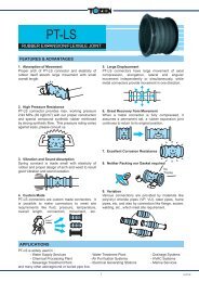
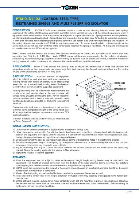
<strong>PTM</strong>-D, <strong>D2</strong>, <strong>D3</strong> (<strong>CARBON</strong> <strong>STEEL</strong> <strong>TYPE</strong>)<br />
RESTRAINED SINGLE AND MULTIPLE SPRING ISOLATOR<br />
DESCRIPTION : TOZEN <strong>PTM</strong>-D series vibration isolators consist of free standing laterally stable steel springs<br />
assembled into welded steel housing assemblies fabricated to limit vertical movement of the isolated equipments when if<br />
equipment loads are reduced or if the equipments are subjected to large external forces. Spring elements are complete with<br />
an internal adjusting and leveling bolt. Tapped holes are provided at the top load plate for bolting to supported equipment.<br />
A 8mm thick non-skid noise absorbing rubber pad is bonded at the bottom plate with holes for bolting to the structure. All<br />
the spring elements are comply to JIS 2704 for semi-permanent use. To assure lateral stability, outside diameter of the<br />
spring elements do not less than 0.8 times of the compressed height of the spring at rated load. All the spring are designed<br />
to provide a minimum of 50% overload capacity.<br />
<strong>PTM</strong>-D series vibration isolator are shipped with standard deflections of 25mm, and available up to 75mm, with load<br />
capacities from 175 Kgs to 8,400 Kgs. Model <strong>PTM</strong>-D spring isolators are recommended for the isolation of vibration<br />
produced by equipment carrying a large fluid load which may be drained, such as boilers and chillers, and for the isolation of<br />
cooling towers, air cooled condensers, etc, where motion due to wind loads must be minimized.<br />
APPLICATION : Model <strong>PTM</strong>-D mounts are typically used to reduce the transmission of noise and vibration into<br />
supporting structures from equipments carrying a large fluid load that may be drained, such as boilers and for cooling<br />
towers, which also require hold down for wind loads.<br />
SPECIFICATION : Vibration isolators for equipment<br />
which is subject to load vibrations and large external or<br />
torquing forces shall consist of laterally stable steel springs<br />
assembled into a welded steel housing assembly designed<br />
to limit vertical movement of the supported equipment.<br />
Housing assembly shall be of fabricated steel members and<br />
consist of a load transfer plate at the top complete with<br />
tapped holes, adjusting and leveling bolts, vertical restraints,<br />
isolation washers and a bottom plate with non-skid noise<br />
isolation pad and holes provided for anchoring to supporting<br />
structure.<br />
Spring elements shall have a outside diameter not less than<br />
0.8 times to the compressed height of the spring rated load.<br />
All springs shall be designed to provide a minimum of 50%<br />
overload capacity.<br />
Vibration isolators shall be Model <strong>PTM</strong>-D, as manufactured<br />
by Tozen Sangyo Co., Ltd.<br />
INSTALLATION INSTRUCTION :<br />
1)<br />
2)<br />
3)<br />
4)<br />
5)<br />
6)<br />
Check that the internal leveling nut is adjusted up to underside of the top plate.<br />
Lift or block up the equipment to 5mm higher than isolator's operating height (see catalogue) and slide the isolators into<br />
position and adjust the leveling nut until the top plate is in contact with equipment base. Insert fastening screws (if used)<br />
through the equipment base into top of the mounting and tighten.<br />
Check alignment of the base so that restraining bolts are central with clearance holes in the restraining bracket.<br />
Transfer the equipment weight to the spring by taking two clockwise turns on each leveling bolt around the unit until<br />
springs are compressed just enough to remove blocks.<br />
Adjust restraining nuts to give 2-3mm clearance between the resilient washer and the underside of the restraining<br />
bracket. Check the leveling again after the system is filled with water.<br />
Tighten the lock nut to lock the assembly.<br />
REMARKS :<br />
a)<br />
b)<br />
c)<br />
d)<br />
e)<br />
When the equipment are not subject to raise to the required height, height saving bracket may be attached to the<br />
equipment. The height of bracket connection from the bottom of the base shall be 50mm less than the isolator's<br />
operating height or to keep a 50mm clearance between the ground and equipment.<br />
DON'T install the equipment on the support of free spring, it would cause an insufficient operating height for the spring<br />
isolator when the installation is completed.<br />
Weight of vertical piping and valves shall be taken over by the suspension hangers or support.<br />
Install the flexible joint at final, follow the pre-extension instruction which may specified or suggested by the flexible joint<br />
manufacturer.<br />
Where bolting is required, avoid a direct metal contact between bolt and mounting, to prevent transmission of acoustical<br />
frequencies; the bolt shank shall be clear in the hole and a rubber washer used under the bolt head. Bolts shall only be<br />
tightened a half turn more than hand tight.<br />
9<br />
VI-0107
<strong>PTM</strong>-D (<strong>CARBON</strong> <strong>STEEL</strong> <strong>TYPE</strong>) 25mm DEFLECTION RESTRAINED SPRING ISOLATOR<br />
MODEL<br />
RATED CAPACITY<br />
(Kgs) (Lbs)<br />
MOUNT<br />
CONSTANT<br />
(Kg/mm)<br />
SPRING<br />
COLOR<br />
OPERATING<br />
HEIGHT<br />
(H) A B<br />
DIMENSION (mm)<br />
C D E F G<br />
<strong>PTM</strong>-D-451M 450 990 18 GREEN<br />
<strong>PTM</strong>-D-601EM 600 1320 24 SILVER<br />
<strong>PTM</strong>-D-826EM 825 1815 33 BROWN<br />
<strong>PTM</strong>-D-1101EM 1100 2420 44 BLUE<br />
<strong>PTM</strong>-D-1401EM 1400 3080 56 BLUE+BROWN<br />
<strong>PTM</strong>-D-1652EM 1650 3630 66 BROWN<br />
<strong>PTM</strong>-D-2202EM 2200 4840 88 BLUE<br />
<strong>PTM</strong>-D-2802EM 2800 6160 112 BLUE+BROWN<br />
<strong>PTM</strong>-D-3304EM 3300 7260 132 BROWN<br />
<strong>PTM</strong>-D-4404EM 4400 9680 176 BLUE<br />
<strong>PTM</strong>-D-5604EM 5600 12320 224 BLUE+BROWN<br />
<strong>PTM</strong>-D-4956EM 4950 10890 198 BROWN<br />
<strong>PTM</strong>-D-6606EM 6600 14520 264 BLUE<br />
<strong>PTM</strong>-D-8406EM 8400 18480 336 BLUE+BROWN<br />
NOTE-1: All springs are free standing and laterally stable. (Outside diameter do not less 0.8 times of compressed height)<br />
NOTE-2: All springs are designed to provide additional travel to solid of at least 50% rated load.<br />
NOTE-3: Please refer to relevant brochure or factory for greater deflection and loading.<br />
10<br />
160 100 184 154 16 184 40 12<br />
180 200 195 155 18 195 40 16<br />
195 170 280 240 20 280 45 16<br />
205<br />
255 280 230 20 280 65 16<br />
<strong>PTM</strong>-<strong>D2</strong> (<strong>CARBON</strong> <strong>STEEL</strong> <strong>TYPE</strong>) 50mm DEFLECTION RESTRAINED SPRING ISOLATOR<br />
MODEL<br />
RATED CAPACITY<br />
(Kgs) (Lbs)<br />
MOUNT<br />
CONSTANT<br />
(Kg/mm)<br />
SPRING<br />
COLOR<br />
OPERATING<br />
HEIGHT<br />
(H) A B<br />
DIMENSION (mm)<br />
C D E F G<br />
<strong>PTM</strong>-<strong>D2</strong>-176 175 385 3.5 ORANGE<br />
<strong>PTM</strong>-<strong>D2</strong>-246 245 539 4.9 VIOLET<br />
<strong>PTM</strong>-<strong>D2</strong>-351 350 770 7 RED<br />
<strong>PTM</strong>-<strong>D2</strong>-526 525 1155 10.5 GREEN<br />
<strong>PTM</strong>-<strong>D2</strong>-751 750 1650 15 SILVER<br />
<strong>PTM</strong>-<strong>D2</strong>-1051 1050 2310 21 SILVER+BROWN<br />
<strong>PTM</strong>-<strong>D2</strong>-1502 1500 3300 30 SILVER<br />
<strong>PTM</strong>-<strong>D2</strong>-2102 2100 4620 42 SILVER+BROWN<br />
<strong>PTM</strong>-<strong>D2</strong>-3004 3000 6600 60 SILVER<br />
<strong>PTM</strong>-<strong>D2</strong>-4204 4200 9240 84 SILVER+BROWN<br />
<strong>PTM</strong>-<strong>D2</strong>-4506 4500 9900 90 SILVER<br />
<strong>PTM</strong>-<strong>D2</strong>-6306 6300 13860 126 SILVER+BROWN<br />
NOTE-1: All springs are free standing and laterally stable.<br />
NOTE-2: All springs are designed to provide additional travel to solid of at least 50% rated load.<br />
NOTE-3: Please consult the representatives for a complete vibration control design.<br />
205 100 200 170 16 200 40 12<br />
225 230 210 170 18 210 40 16<br />
240 200 310 270 20 310 50 16<br />
250 300 310 260 20 310 65<br />
<strong>PTM</strong>-<strong>D3</strong> (<strong>CARBON</strong> <strong>STEEL</strong> <strong>TYPE</strong>) 75mm DEFLECTION RESTRAINED SPRING ISOLATOR<br />
MODEL<br />
RATED CAPACITY<br />
(Kgs) (Lbs)<br />
MOUNT<br />
CONSTANT<br />
(Kg/mm)<br />
SPRING<br />
COLOR<br />
OPERATING<br />
HEIGHT<br />
(H) A B<br />
DIMENSION (mm)<br />
C D E F G<br />
<strong>PTM</strong>-<strong>D3</strong>-180ES 180 396 2.4 ORANGE<br />
<strong>PTM</strong>-<strong>D3</strong>-255ES 255 561 3.4 VIOLET<br />
240 100 220 180 18 220 50 M16<br />
<strong>PTM</strong>-<strong>D3</strong>-375ES 375 825 5 RED<br />
<strong>PTM</strong>-<strong>D3</strong>-555EL 555 1221 7.4 SILVER<br />
<strong>PTM</strong>-<strong>D3</strong>-810EL 810 1782 10.8 YELLOW 274 125 245 205 18 245 40 M16<br />
<strong>PTM</strong>-<strong>D3</strong>-1065EL 1065 2343 14.2 YELLOW+BROWN<br />
<strong>PTM</strong>-<strong>D3</strong>-1112EL 1110 2442 14.8 SILVER<br />
<strong>PTM</strong>-<strong>D3</strong>-1622EL 1620 3564 21.6 YELLOW 290 282 245 205 18 245 40 M16<br />
<strong>PTM</strong>-<strong>D3</strong>-2132EL 2130 4686 28.4 YELLOW+BROWN<br />
NOTE-1: All springs are free standing and laterally stable.<br />
NOTE-2: All springs are designed to provide additional travel to solid of at least 50% rated load.<br />
NOTE-3: Please consult the representatives for a complete vibration control design.<br />
16<br />
VI-0107
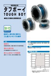
<strong>PTM</strong>-D (DUCTILE IRON <strong>TYPE</strong>)<br />
RESTRAINED SINGLE AND MULTIPLE SPRING ISOLATOR<br />
DESCRIPTION : TOZEN <strong>PTM</strong>-D series vibration<br />
isolators consist of free standing laterally stable steel<br />
springs assembled into ductile iron housing assemblies<br />
fabricated to limit vertical movement of the isolated<br />
equipments when if equipment loads are reduced or if the<br />
equipments are subjected to large external forces. Spring<br />
elements are complete with an internal adjusting and<br />
leveling bolt. Holes are provided at the upper plate for<br />
bolting to supported equipment. A 10mm thick non-skid<br />
noise absorbing rubber pad is bonded at the bottom plate<br />
with holes for bolting to the structure. All the spring<br />
elements are comply to JIS 2704 for semi-permanent use.<br />
To assure lateral stability, outside diameter of the spring<br />
elements do not less than 0.8 times of the compressed<br />
height of the spring at rated load. All the spring are<br />
designed to provide a minimum of 50% overload capacity.<br />
<strong>PTM</strong>-D series vibration isolator are shipped with standard<br />
deflections of 25 and 50 mm, and available up to 50mm,<br />
with load capacities from 450 Kgs to 5,600 Kgs. Model<br />
<strong>PTM</strong>-D spring isolators are recommended for the isolation<br />
of vibration produced by equipment carrying a large fluid<br />
load which may be drained, such as boilers and chillers,<br />
and for the isolation of cooling towers, air cooled<br />
condensers, etc, where motion due to wind loads must be<br />
minimized.<br />
APPLICATION : Model <strong>PTM</strong>-D mounts are typically<br />
used to reduce the transmission of noise and vibration into<br />
supporting structures from equipments carrying a large<br />
fluid load that may be drained, such as boilers and for<br />
cooling towers, which also require hold down for wind<br />
loads.<br />
<strong>PTM</strong>-D-3304EM, 4404EM, 5604EM<br />
<strong>PTM</strong>-<strong>D2</strong>-3004, 4204<br />
* These images are sectioned for better appearance.<br />
SPECIFICATION : Vibration isolators for equipment<br />
which is subject to load vibrations and large external or<br />
torquing forces shall consist of laterally stable steel springs<br />
assembled into a ductile iron housing assembly designed to<br />
limit vertical movement of the supported equipment.<br />
Housing assembly shall be of ductile iron members and<br />
consist of a load transfer plate at the top complete with holes,<br />
adjusting and leveling bolts, vertical restraints, isolation<br />
washers and a bottom plate with non-skid noise isolation pad<br />
and holes provided for anchoring to supporting structure.<br />
Spring elements shall have a outside diameter not less than<br />
0.8 times to the compressed height of the spring rated load. All<br />
springs shall be designed to provide a minimum of 50%<br />
overload capacity.<br />
Vibration isolators shall be Model <strong>PTM</strong>-D, as manufactured by<br />
Tozen Sangyo Co., Ltd.<br />
11<br />
<strong>PTM</strong>-D-451M, 601EM, 826EM, 1101EM, 1401EM<br />
<strong>PTM</strong>-<strong>D2</strong>-176, 246, 351, 526, 751, 1051<br />
<strong>PTM</strong>-D-1652EM, 2202EM, 2802EM<br />
<strong>PTM</strong>-<strong>D2</strong>-1502, 2102<br />
VI-0107
<strong>PTM</strong>-D (DUCTILE IRON <strong>TYPE</strong>) 25mm DEFLECTION RESTRAINED SPRING ISOLATOR<br />
MODEL<br />
RATED CAPACITY<br />
(Kgs) (Lbs)<br />
MOUNT<br />
CONSTANT<br />
(Kg/mm)<br />
SPRING<br />
COLOR<br />
OPERATING<br />
HEIGHT<br />
(H) A B<br />
DIMENSION (mm)<br />
C D E F G I<br />
<strong>PTM</strong>-D-451M 450 990 18 GREEN<br />
<strong>PTM</strong>-D-601EM 600 1320 24 SILVER<br />
<strong>PTM</strong>-D-826EM 825 1815 33 BROWN<br />
<strong>PTM</strong>-D-1101EM 1100 2420 44 BLUE<br />
<strong>PTM</strong>-D-1401EM 1400 3080 56 BLUE+BROWN<br />
<strong>PTM</strong>-D-1652EM 1650 3630 66 BROWN<br />
<strong>PTM</strong>-D-2202EM 2200 4840 88 BLUE<br />
<strong>PTM</strong>-D-2802EM 2800 6160 112 BLUE+BROWN<br />
<strong>PTM</strong>-D-3304EM 3300 7260 132 BROWN<br />
<strong>PTM</strong>-D-4404EM 4400 9680 176 BLUE<br />
<strong>PTM</strong>-D-5604EM 5600 12320 224 BLUE+BROWN<br />
12<br />
170 172 121 137 86 16 30 88 14<br />
170 180 200 136 156 20 40 118 18<br />
185 255 167 211 123 20 48.5 135 18<br />
<strong>PTM</strong>-<strong>D2</strong> (DUCTILE IRON <strong>TYPE</strong>) 50mm DEFLECTION RESTRAINED SPRING ISOLATOR<br />
MODEL<br />
RATED CAPACITY<br />
(Kgs) (Lbs)<br />
MOUNT<br />
CONSTANT<br />
(Kg/mm)<br />
SPRING<br />
COLOR<br />
OPERATING<br />
HEIGHT<br />
(H) A B<br />
DIMENSION (mm)<br />
C D E F G I<br />
<strong>PTM</strong>-<strong>D2</strong>-176 175 385 3.5 ORANGE<br />
<strong>PTM</strong>-<strong>D2</strong>-246 245 539 4.9 VIOLET<br />
<strong>PTM</strong>-<strong>D2</strong>-351 350 770 7 RED<br />
<strong>PTM</strong>-<strong>D2</strong>-526 525 1155 10.5 GREEN<br />
<strong>PTM</strong>-<strong>D2</strong>-751 750 1650 15 SILVER<br />
<strong>PTM</strong>-<strong>D2</strong>-1051 1050 2310 21 SILVER+BROWN<br />
<strong>PTM</strong>-<strong>D2</strong>-1502 1500 3300 30 SILVER<br />
<strong>PTM</strong>-<strong>D2</strong>-2102 2100 4620 42 SILVER+BROWN<br />
<strong>PTM</strong>-<strong>D2</strong>-3004 3000 6600 60 SILVER<br />
<strong>PTM</strong>-<strong>D2</strong>-4204 4200 9240 84 SILVER+BROWN<br />
NOTE-1: All springs are free standing and laterally stable. (Outside diameter do not less 0.8 times of compressed height)<br />
NOTE-2: All springs are designed to provide additional travel to solid of at least 50% rated load.<br />
NOTE-3: Please refer to relevant brochure or factory for greater deflection and loading.<br />
INSTALLATION INSTRUCTION :<br />
1)<br />
2)<br />
3)<br />
4)<br />
5)<br />
6)<br />
210 190 130 152 95 16 38 106 16<br />
210 232 196 187 152 20 42 120 16<br />
220 300 200 260 162 20 66.5 170<br />
Check that the internal leveling nut is adjusted up to underside of the upper plate.<br />
Lift or block up the equipment to 5mm higher than isolator's operating height (see catalogue) and slide the isolators into<br />
position and adjust the leveling nut until the upper plate is in contact with equipment base. Insert fastening screws (if<br />
used) through the equipment base into top of the mounting and tighten.<br />
Check alignment of the base so that restraining bolts are central with clearance holes in the restraining bracket.<br />
Transfer the equipment weight to the spring by taking two counter-clockwise turns on each leveling bolt around the unit<br />
until springs are compressed just enough to remove blocks.<br />
Adjust restraining nuts to give 2-3mm clearance between the restrain washer and the underside of the restraining<br />
bracket. Check the leveling again after the system is filled with water.<br />
Tighten the lock nut to lock the assembly.<br />
REMARKS :<br />
a)<br />
b)<br />
c)<br />
d)<br />
e)<br />
When the equipment are not subject to raise to the required height, height saving bracket may be attached to the<br />
equipment. The height of bracket connection from the bottom of the base shall be 50mm less than the isolator's<br />
operating height or to keep a 50mm clearance between the ground and equipment.<br />
DON'T install the equipment on the support of free spring, it would cause an insufficient operating height for the spring<br />
isolator when the installation is completed.<br />
Weight of vertical piping and valves shall be taken over by the suspension hangers or support.<br />
Install the flexible joint at final, follow the pre-extension instruction which may specified or suggested by the flexible joint<br />
manufacturer.<br />
Where bolting is required, avoid a direct metal contact between bolt and mounting, to prevent transmission of acoustical<br />
frequencies; the bolt shank shall be clear in the hole and a rubber washer used under the bolt head. Bolts shall only be<br />
tightened a half turn more than hand tight.<br />
20<br />
VI-0107