12” x 37” Gap Bed Lathe - Harbor Freight Tools
12” x 37” Gap Bed Lathe - Harbor Freight Tools
12” x 37” Gap Bed Lathe - Harbor Freight Tools

You also want an ePaper? Increase the reach of your titles
YUMPU automatically turns print PDFs into web optimized ePapers that Google loves.
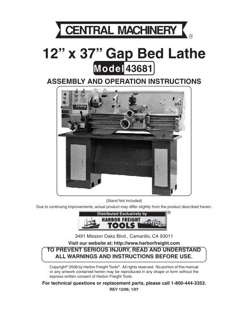
<strong>12”</strong> x <strong>37”</strong> <strong>Gap</strong> <strong>Bed</strong> <strong>Lathe</strong><br />
Model 43681<br />
AsseMBLy And OperAtiOn instructiOns<br />
(Stand Not Included)<br />
Due to continuing improvements, actual product may differ slightly from the product described herein.<br />
®<br />
3491 Mission Oaks Blvd., Camarillo, CA 93011<br />
Visit our website at: http://www.harborfreight.com<br />
tO preVent seriOus injury, reAd And understAnd<br />
ALL wArninGs And instructiOns BefOre use.<br />
Copyright © 2006 by <strong>Harbor</strong> <strong>Freight</strong> <strong>Tools</strong> ® . All rights reserved. No portion of this manual<br />
or any artwork contained herein may be reproduced in any shape or form without the<br />
express written consent of <strong>Harbor</strong> <strong>Freight</strong> <strong>Tools</strong>.<br />
for technical questions or replacement parts, please call 1-800-444-3353.<br />
reV 12/06; 1/07
Motor: 2HP, 1700 RPM, Reversible<br />
specificAtiOns<br />
Max. tool shank size: 3/4” x 3/4” <strong>Lathe</strong> Bit<br />
power required: 220 V / 60 Hz, 1-Phase tool post travel: Max. 3.5” , 0.001” per scale<br />
drive: Belt/Gear<br />
cross slide travel: 5.9”, 0.002” per scale<br />
swing Over <strong>Bed</strong>: <strong>12”</strong><br />
(Total Cut)<br />
swing Over <strong>Gap</strong>: 18.8”<br />
Longitudinal feed range: 0.005” - 0.0165” /R<br />
width of <strong>Gap</strong>: 7”<br />
(16 Steps)<br />
center to center: <strong>37”</strong><br />
cross feed range: 0.0014” - 0.0049 /R<br />
spindle Bore taper: MT5<br />
(16 Steps)<br />
spindle Bore: 1.5”<br />
tailstock travel: Max 3.6”<br />
three jaw chuck diameter: 6”<br />
tailstock spindle Bore taper: MT3<br />
spindle speed: 18 Speed<br />
thread indicator: Yes<br />
spindle speed range:<br />
thread feeding:<br />
72; 82; 147; 168; 240; 275; 325; 370; 415; 476; sAe: 4 - 112 TPI, Total 40 Setting<br />
660; 760; 850; 975; 1080; 1240; 1380; 1600 Metric: 0.25 - 7.5 mm, Total 19 Setting<br />
<strong>Bed</strong> way heat treatment: 46-52 HRC<br />
tool post type: 4-Position<br />
net weight: 838 lb.<br />
(1) Steady Rest<br />
(1) Follow Rest<br />
(2) Dead Center: #3<br />
(1) Center Sleeve: #5 / 3<br />
(1) Live Center: MT3<br />
(1) 6” 4-Jaw Chuck<br />
(1) Back Plate for 4-Jaw Chuck<br />
(1) Tool Post Wrench<br />
(1) Double End Wrenches 13-16<br />
AccessOries<br />
(5) Hex Wrenches (3, 4, 5, 6, 8 mm)<br />
(1) Screwdriver<br />
(1) Oil Gun<br />
(5) Changing Gears: T30, T32, T40 (2<br />
pcs), T127/120<br />
(1) Face Plate 9-3/4”<br />
(1) Splash Guard<br />
(1) Oil Tray<br />
sAVe this MAnuAL<br />
You will need the manual for the safety warnings and cautions, assembly instructions, operating<br />
procedures, maintenance procedures, trouble shooting, parts list, and diagram. Keep<br />
your invoice with this manual. Write the invoice number on the inside of the front cover.<br />
Keep both this manual and your invoice in a safe, dry place for future reference.<br />
reAd ALL instructiOns BefOre usinG this tOOL!<br />
nOtice<br />
the warnings, cautions, and instructions discussed in this instruction manual cannot cover all<br />
possible conditions and situations that may occur. it must be understood by the operator that<br />
common sense and caution are factors which cannot be built into this product, but must be supplied<br />
by the operator.<br />
SKU 43681 for technical questions, please call 1-800-444-3353.<br />
REV 02/07<br />
Page 2
1.<br />
2.<br />
3.<br />
4.<br />
5.<br />
6.<br />
7.<br />
8.<br />
9.<br />
10.<br />
11.<br />
12.<br />
sAfety wArninG & cAutiOns<br />
reAd ALL instructiOns BefOre usinG this tOOL!<br />
Keep wOrK AreA cLeAn. Cluttered areas invite injuries.<br />
OBserVe wOrK AreA cOnditiOns. Do not use tools in damp, wet, or poorly lit<br />
locations. Don’t expose to rain. Keep work area well lit. Do not use electrically powered<br />
equipment in the presence of flammable gases or liquids.<br />
Keep chiLdren AwAy. Children must never be allowed in the work area. Do not let<br />
them handle machines, tools, or equipment.<br />
stOre idLe eQuipMent. When not in use, tools must be locked up in a dry location<br />
to inhibit rust. Always lock up tools and keep out of reach of children.<br />
dO nOt fOrce the tOOL. It will do the job better and more safely at the rate for<br />
which it was intended. Do not use inappropriate attachments in an attempt to exceed<br />
the tool’s capacities.<br />
use the riGht tOOL fOr the jOB. Do not attempt to force a small tool or attachment<br />
to do the work of a larger industrial tool. There are certain applications for which<br />
this tool was designed. Do not modify this tool, and do not use this tool for a purpose<br />
for which it was not intended.<br />
dress prOperLy. Do not wear loose clothing or jewelry, as they can be caught in<br />
moving parts. Non-skid footwear is recommended. Wear restrictive hair covering to<br />
contain long hair. Always wear appropriate work clothing.<br />
use eye, eAr And BreAthinG prOtectiOn. Always wear ANSI approved impact<br />
safety goggles if you are producing metal filings or wood chips. Wear an ANSI<br />
approved dust mask or respirator when working around metal, wood, and chemical<br />
dusts and mists. Use ANSI approved ear protection when working in a loud or noisy<br />
environment.<br />
dO nOt ABuse the pOwer cOrd. Protect the power cord from damage, either<br />
from impacts, pulling or corrosive materials. Do not yank machine’s cord to disconnect<br />
it from the receptacle.<br />
dO nOt OVerreAch. Keep proper footing and balance at all times. Do not reach<br />
over or across running machines.<br />
MAintAin tOOLs with cAre. Keep tools sharp and clean for better and safer performance.<br />
Follow instructions for lubricating and changing accessories. Inspect power<br />
cord periodically and, if damaged, have it repaired by an authorized technician. Control<br />
handle and power switch must be kept clean, dry, and free from oil and grease at all<br />
times.<br />
reMOVe AdjustinG Keys And wrenches. Be sure that keys and adjusting<br />
wrenches are removed from the tool or machine work surface before operation.<br />
SKU 43681 for technical questions, please call 1-800-444-3353.<br />
Page 3
13.<br />
14.<br />
15.<br />
16.<br />
17.<br />
AVOid unintentiOnAL stArtinG. Be sure that you are prepared to begin work<br />
before turning the start switch on.<br />
stAy ALert. Watch what you are doing. Do not operate this machine when you are<br />
tired.<br />
dO nOt OperAte this MAchine whiLe under the infLuence Of ALcOhOL,<br />
druGs, Or prescriptiOn Medicines.<br />
checK fOr dAMAGed pArts. Before using any tool, any part that appears damaged<br />
should be carefully checked to determine that it will operate properly and perform its<br />
intended function. Check for alignment and binding of moving parts, any broken parts<br />
or mounting fixtures, and any other condition that may affect proper operation. Any part<br />
that is damaged should be properly repaired or replaced by a qualified technician. Do<br />
not use the tool if any switch does not turn on and off properly.<br />
repLAceMent pArts And AccessOries. When servicing, use only identical<br />
replacement parts intended for use with this tool. Replacement parts are available from<br />
<strong>Harbor</strong> <strong>Freight</strong> <strong>Tools</strong>. Use of any other parts will void the warranty.<br />
speciAL wArninGs when usinG this Bench LAthe<br />
Using this Bench <strong>Lathe</strong> may create special hazards.<br />
Take particular care to safeguard yourself and those around you.<br />
electrical safety. Never operate any tool if there is an electrical hazard. Never operate<br />
an electrical tool in wet conditions. Never operate a tool with an improper electrical cord<br />
or extension cord. Never operate an electrical tool unless you are plugged into a properly<br />
grounded outlet, which supplies 115 Volts at 60 Hz. We recommend you use a circuit<br />
which is protected by an appropriate circuit breaker.<br />
ejected Material. Use safe practices to avoid injury from ejected material. Because the<br />
lathe and the workpieces turn at high speed, there is a danger of being injured by materials<br />
that may be ejected. Always wear ANSI-certified eye protection. Never attempt to work<br />
on any item if it is not adequately held. Always stand to one side of the plane in which the<br />
materials are spinning, to avoid being hit if an item is ejected. Never allow bystanders to be<br />
in the proximity of the lathe while in operation.<br />
entanglement. Use extreme caution to prevent loose materials from being caught in<br />
the machine. Never operate this lathe with loose clothing, long hair, jewelry, or other items<br />
which may become caught in the tools or workpieces. In case of entanglement, press the<br />
OFF switch immediately.<br />
NOTICE: No list of warnings can be all inclusive. The operator must supply<br />
common sense, and operate this tool in a safe manner.<br />
SKU 43681 for technical questions, please call 1-800-444-3353.<br />
Page 4
BAsic cOMpOnents And feAtures Of yOur #43681 GAp <strong>Bed</strong> LAthe<br />
reference description<br />
A Press Switch<br />
C Emergency Stop Control<br />
D Indicator Light<br />
E Gear Box<br />
F Direction Control<br />
G Speed Control A<br />
H Speed Control B<br />
I Oil Gauge<br />
J Chuck<br />
K <strong>Bed</strong>way<br />
L Tool Holder<br />
M Tool Post Clamping Lever<br />
N Compound Slide<br />
O Steady Rest<br />
P Tailstock Quill<br />
Q Tailstock Clamping Lever<br />
R Tailstock<br />
S Tailstock Handwheel<br />
reference description<br />
T Tailstock Base<br />
U Lead Screw<br />
V Control Lever<br />
W Thread Dial<br />
X Half Nut Lever<br />
Y Cross/Longitudinal Feed Lever<br />
Z Cross Slide Handwheel<br />
AA Saddle Handwheel<br />
BB<br />
Feedrod & Leadscrew<br />
Exchange Lever<br />
CC Change Gear Control A<br />
EE Change Gear Control B<br />
FF Oil Tray<br />
GG Power Cord<br />
HH Leadscrew Chart<br />
KK Splash Guard<br />
MM Chuck Protection Cover<br />
parts references in this text:<br />
When parts are identified with letters, please refer to the diagram on this page.<br />
When parts are identified with numbers, refer to parts lists and diagrams starting on page 16.<br />
SKU 43681 for technical questions, please call 1-800-444-3353.<br />
Page 5
unpAcKinG, AsseMBLy, And set up.<br />
Basic assembly and adjustment of your new lathe was completed before being shipped.<br />
Final assembly and adjustments must be made before operating your new lathe.<br />
first find a suitable location for your lathe.<br />
1.<br />
2.<br />
3.<br />
4.<br />
The floor or work table which you place your<br />
lathe on must be level, solid, and resistant to<br />
vibration.<br />
Your lathe should be positioned in an area which<br />
is protected from the weather, especially water<br />
and moisture.<br />
You should provide good light to work in, and Fig.1 Mounting bolts in the headstock.<br />
adequate space to operate and maintain the<br />
machine, as well as to handle work materials which will be loaded in the machine.<br />
You will need an appropriate power supply to operate the machine, which requires 220<br />
V~, 60 Hz, single phase current, and must be protected by a suitable circuit breaker.<br />
wArninG: Consult a licensed electrician if you are not completely sure that your power<br />
supply is correct and safe.<br />
complete Assembly.<br />
You will have to assemble the lathe onto the oil tray<br />
(FF) and then onto a bench top (not included) or<br />
metal stand.<br />
please note: the bench top must be able to withstand<br />
the weight of the <strong>Lathe</strong> (838 lb.) as well as<br />
the weight of the workpiece. do not exceed the<br />
maximum weight capacity of 1320 lb.<br />
if you choose to use a metal stand with this<br />
<strong>Lathe</strong>, the only stand that will fit with this <strong>Lathe</strong><br />
is sKu 95647 (sold separately).<br />
1.<br />
2.<br />
3.<br />
4.<br />
Fig.2 Mounting bolts in the tailstock.<br />
Check to be sure that the bench is level and stable on the shop floor. If you need to repair<br />
the floor, do it now to be sure you have a solid, level surface to mount the machine.<br />
Once the work bench is positioned properly on a solid level floor, place the oil tray (FF)<br />
on the bench. Using the mounting holes on the oil tray (FF) as reference, drill matching<br />
1/2” holes into the wood bench. Always check to make sure no obstructions are in<br />
the drilling path.<br />
Place the angled iron levelers between the oil tray (FF) and the bench top. Check the<br />
level and position of the bench top again to be sure that when the <strong>Lathe</strong> is positioned<br />
on the bench and oil tray (FF) it will be level, solid and aligned with the mounting holes<br />
in the bench and tray.<br />
Using a drill and other hardware (not included) bolt the work bench to the floor before<br />
putting <strong>Lathe</strong> on the workbench to keep the bench and <strong>Lathe</strong> in place during use.<br />
SKU 43681 for technical questions, please call 1-800-444-3353.<br />
Page 6
hOistinG And LeVeLinG this MAchine<br />
wArninG: dO nOt AtteMpt tO Lift the LAthe By yOurseLf.<br />
this tool weighs over 800 lb., and cannot be lifted safely by one or several strong men.<br />
Be sure this lathe is balanced on the hoist or lift you will use to move it before moving.<br />
1.<br />
2.<br />
3.<br />
4.<br />
5.<br />
6.<br />
Before hoisting, lifting or moving this machine, move the tailstock and apron to the far<br />
right end of the bedway (away from the headstock) and lock them in place there. This<br />
will help to balance the overall mass of the machine near the center.<br />
Use pads (not included) to protect the lathe from damage by the equipment used to hoist it.<br />
Use a hydraulic lift, fork lift, or hoist to position the lathe onto the bench (or SKU 95647 Stand).<br />
When the lathe is positioned on the oil tray and bench, align the mounting holes and<br />
drop in the mounting bolts.<br />
Check the level of the machine. Using a spirit level, check to be sure that the bed of the<br />
lathe is level both horizontally and front to back. If there is any out of level, correct it now.<br />
Depending on your installation, use the angled iron levelers to adjust the machine into<br />
exact level front to back and side to side. Check both ends of the tool before being satisfied.<br />
Be sure the machine is level, positioned solidly, and is resistant to vibration.<br />
Fasten the lathe to the bench and oil tray (FF) by inserting a bolt through a lock washer<br />
from the inside of the bench and upward through the oil tray and lathe. Fasten with<br />
a washer and nut. Repeat this for each of the four mounting holes in the headstock,<br />
and both mounting holes in the tailstock. Tighten securely. Recheck and readjust level<br />
if required.<br />
note: Periodically recheck the level of the machine to ensure that it remains level while in use.<br />
630<br />
Figure 3. Overall dimensions of this machine,<br />
and oil tray dimensions. Dimensions<br />
are given in millimeters. Measure your own<br />
machine for any variations before using<br />
these dimensions.<br />
605<br />
1704<br />
SKU 43681 for technical questions, please call 1-800-444-3353.<br />
460<br />
Page 7
the heAdstOcK<br />
The headstock includes a Gear box (E) which contains<br />
gears and a belt drive. The gears are controlled<br />
by controls (F), (G), and (H). The belt drive<br />
transmits the motor power to the drive system of the<br />
machine.<br />
1.<br />
2.<br />
3.<br />
4.<br />
The motor and drive belt are installed and adjusted<br />
when delivered. However, you should<br />
check the adjustment of the drive belt before<br />
using this lathe.<br />
Check the belt tension by pressing in the middle<br />
with your finger. You should be able to depress<br />
it approximately 1/2 inch. If the belt is too tight,<br />
it will wear the bearings, and if too loose, it will<br />
slip on the pulleys and wear out prematurely.<br />
If it is necessary to adjust the belt tension, do so<br />
by adjusting the bolt and locknut assembly on<br />
the underside of the motor. The motor mounted<br />
on the back of the headstock.<br />
Four additional change gears are included for<br />
use in cutting metric and SAE threads. Refer<br />
to the lead screw chart on the headstock for<br />
the gears required for the thread pitches you<br />
want.<br />
Please refer to the section on threading for<br />
more information.<br />
Fig.4 Inside the Gear Box.<br />
Fig.5 Motor mount and adjustment.<br />
Fig.6 Headstock Controls.<br />
SKU 43681 for technical questions, please call 1-800-444-3353.<br />
Page 8
SPEED AND POWER CONTROLS<br />
rn your lathe on and off, and control its speed and direction from the main control panel.<br />
Switch<br />
speed And pOwer cOntrOLs<br />
he power switch You can to turn<br />
SPEED lathe the on machine and AND off POWER and ON. control Push<br />
CONTROLS<br />
speed the switch and direction again to from turn the main control panel.<br />
turn your lathe on and off, and control its speed and direction from the main control panel.<br />
e OFF.<br />
the power switch<br />
dicator Light (D) will be on when the machine is running.<br />
er Switch<br />
1. Turn the Emergency Stop Switch (C) clockwise; the Indicator<br />
h mergency, the power you switch can<br />
Light<br />
to stop turn the<br />
(D) will<br />
the machine<br />
light<br />
machine by<br />
up. The<br />
ON. pressing<br />
Spindle<br />
Push<br />
will<br />
the the<br />
not<br />
switch Emergency<br />
turn without<br />
again Stop<br />
operating<br />
to turn<br />
). ine OFF. the Control Lever (V).<br />
Indicator Light (D) will be on ��<br />
when the machine is running.<br />
n emergency, 2. you The can Press stop the Switch machine (A) is used by pressing to run the the spindle Emergency temporarily Stop to<br />
(C).<br />
allow the gears to engage when changing speed gears. When<br />
you release the switch, the spindle will stop.<br />
��<br />
Fig.7 Power Switch.<br />
Direction Controls 3. In an emergency, you can stop the machine by pressing the<br />
Emergency Stop Control (C).<br />
ot change the settings of these controls if the motor is running.<br />
Fig.7 Power Switch.<br />
Fig.7 Power Switch.<br />
the speed and direction controls<br />
nd Direction power before Controls changing these settings.<br />
Note: Do not change the settings of these controls if the motor is running.<br />
o Spindle not change Speed<br />
Shut the can<br />
OFF settings be controlled<br />
the power of these before controls by setting<br />
changing if the the<br />
these motor Speed<br />
settings. is Control running. knobs (G) and (H). Refer<br />
t F on the the power Headstock before to changing the right these of the settings. knobs to determine the proper setting for the desired<br />
The Spindle Speed can be controlled by setting the Speed Control knobs (G) and (H).<br />
ation he Spindle speed. Speed Nine Refer can speeds to be the controlled are chart possible on the by Headstock setting from the 64 to Speed the to right 1500 Control of rpm. the knobs knobs The to direction (G) determine and (H). the may proper Refer be<br />
using art on Direction the Headstock Control setting to for the (F). the right desired of the spindle knobs rotation to determine speed. Eighteen the proper speeds setting are possible for the from desired 72 to<br />
rotation speed. Nine 1600 RPM. speeds The are direction possible may be from controlled 64 to using 1500 Direction rpm. The Control direction (F). may be<br />
d using Direction<br />
Quick change<br />
Control<br />
Gearbox<br />
(F).<br />
nge Gearbox<br />
The headstock is equipped with a quick change gearbox to control the rate of the spindle to<br />
ock<br />
hange<br />
is equipped<br />
Gearbox<br />
with a quick change gearbox to control the rate of the spindle to the<br />
the lead screw and feed rod, when it is used to cut threads, or for turning or facing.<br />
dstock and feed is equipped rod, when with it is a used quick to change cut threads, gearbox or to for control turning the or rate facing. of the spindle to the<br />
1. Controls (CC) and (EE) may be used<br />
ew ls (CC) and feed and rod, (EE) when may<br />
in combination<br />
it be is used used in<br />
to<br />
to combination<br />
control<br />
cut threads,<br />
the feed<br />
or to<br />
rate.<br />
for turning or facing.<br />
l trols the feed (CC) rate. and Please (EE) Please may refer refer be to to used the the lead in lead combination screw screw chart chart (HH) to<br />
trol or the the desired feed rate. setting. Please for the desired refer to setting. the lead screw chart<br />
ange ) for the gears desired may need setting. to be replaced in order to<br />
change gears<br />
2.<br />
may<br />
The<br />
need<br />
change<br />
to be<br />
gears<br />
replaced<br />
may need<br />
in order<br />
to be<br />
to<br />
re-<br />
e the correct setting. placed Be to sure achieve the machine the correct is turned setting.<br />
eve is unplugged the correct from setting. Be sure the machine is turned<br />
Be sure its power the machine supply is turned before off and is<br />
and is unplugged from unplugged its power from its supply power before<br />
ting to replace the gears. Select the gears supply required before<br />
mpting to replace replacing the gears. the Select gears. the Select gears the required gears<br />
he the lead lead screw screw chart. chart. required from the lead screw chart.<br />
Exchange change Lever Lever (BB) (BB) is is used used to to activate activate and and control control<br />
3. When the Exchange Lever (BB) is in the<br />
direction ection of of rotation. rotation. When When the the lever lever is is in in the the middle<br />
middle<br />
middle position, the Lead Screw (118)<br />
n, tion, the the lead lead screw screw is is parked. parked. When When the the lever lever is is to to<br />
and Feeding Rod (107) are locked. When<br />
right, ht, the the lead lead screw screw Exchange is is running, running, Lever and and (BB) the the is machine to machine the right, can can the<br />
d sed to to turn turn threads. threads. Lead When When Screw the the lever (118) lever is is is to running to the the left, left, and the the<br />
rew screw is reversed, is reversed, and machine and the the machine can machine be used may to may turn be be the used used threads. for. for.<br />
rnal or external machining When Exchange or face Lever cutting. (BB) is to the<br />
Fig.8<br />
Fig.8<br />
Lead<br />
Lead<br />
Screw<br />
Screw<br />
Chart.<br />
Chart.<br />
l or external machining or face cutting.<br />
Fig.8 Lead Screw Chart.<br />
l or external machining or face cutting.<br />
Fig.8 Lead Screw Chart.<br />
half nut is engaged left, or the disengaged Feeding Rod using is running the Half and the Nut Lever<br />
lf<br />
Note<br />
nut<br />
that<br />
is engaged<br />
the half machine or<br />
nut<br />
disengaged<br />
must can be be engaged used using set the<br />
for Half automatic the lead<br />
Nut feeding. screw<br />
Lever<br />
to function properly.<br />
ote that the half nut must be engaged for the lead screw to function properly.<br />
4.<br />
The half nut is engaged or disengaged using the Half Nut Lever (X). Note that the half<br />
nut must be engaged for the lead screw to function properly.<br />
SKU 43681 for technical questions, please call 1-800-444-3353.<br />
KU # 43681<br />
U # 43681<br />
Page 9
AprOn<br />
the function of the Apron is to support the toolpost, and to be carried along the<br />
workpiece by the lead screw.<br />
1.<br />
2.<br />
3.<br />
4.<br />
5.<br />
6.<br />
7.<br />
8.<br />
Use the Control Lever (V) to start the motion<br />
of the Spindle, and to rotate it forward<br />
or reverse.<br />
To operate the lever, push it toward the<br />
headstock, then move it up or down. Moving<br />
the lever down will cause the spindle<br />
to rotate forward, moving it up will cause<br />
the spindle to rotate in reverse. Placing the<br />
lever in the middle will cause the spindle<br />
not to rotate.<br />
The Half Nut Lever (X) for engaging the<br />
lead screw is mounted on the right side<br />
of the apron.<br />
The Half Nut Lever (X) is used to engage<br />
or remove the half nut from the lead screw.<br />
This lever is mounted on the front of the<br />
apron. Engage the half nut only when moving<br />
the apron in a longitudinal direction<br />
along the workpiece.<br />
Fig.9 The Apron.<br />
The Cross/Longitudinal Feed Lever (Y) is used to determine the direction of travel of<br />
the tool on the workpiece. With the lever up, and the gear engaged, the apron will travel<br />
in a longitudinal direction along the workpiece; for example when threading. With the<br />
lever down, and the half nut disengaged, the tool post will travel horizontally across the<br />
workpiece; for example when face cutting.<br />
Note: The interlock will prevent the half nut from being engaged when the Feed Lever<br />
(Y) is down in the cross feed position.<br />
For threading, put the Feed rod & Leadscrew Exchange Lever (BB) to the right to start<br />
the lead screw, then move the Cross/Longitudinal Feed Lever (Y) to the center, and<br />
engage the half nut, using the Half Nut Lever (X). This will cause the lead screw to<br />
rotate, and the apron to move to the right.<br />
You can also control the direction of travel of the apron using the Direction Control (F).<br />
Rotating this control to the right will cause the carriage to move to the right. Rotating<br />
this control to the left will cause the apron to move to the left.<br />
SKU 43681 for technical questions, please call 1-800-444-3353.<br />
Page 10
the threAdinG diAL<br />
when the threads on the lead screw and on the workpiece<br />
are not in an integer ratio, it is necessary to use the threading<br />
dial to control successive cuts. Determine this ratio by<br />
dividing the desired TPI of the workpiece (for example 24 TPI)<br />
by the thread pitch of the lead screw (8 TPI). This example<br />
results in an integer ratio of 3:1. A desired thread pitch of 26<br />
TPI (for example) on the workpiece would require use of the<br />
threading dial.<br />
1. When the threads on the workpiece are not in an integer<br />
proportion to the threads on the lead screw, it is<br />
necessary to operate the half nut intermittently. This is<br />
controlled by using the threading dial.<br />
2. The Threading Dial (W) is located on the right side of<br />
the apron.<br />
3. The dial is marked with four numbered lines, 1, 2, 3,<br />
and 4. Between each numbered line is an unnumbered<br />
line. On the dial there is also a fixed reference line.<br />
4. When the threading dial is engaged with the lead screw,<br />
the dial will rotate.<br />
5. There is an instruction plate attached to the threading<br />
dial explaining the use of the dial, depending on the Fig.10 Threading Dial.<br />
specific thread you are cutting.<br />
6. For thread cutting, engage the half nut at the appropriate numbers shown on the threading<br />
dial. 1-4 means the half nut can be engaged at any of the numbered lines 1, 2, 3,<br />
or 4. For successive cuts, only numbered lines must be used. 1-3 / 2-4 on the scale<br />
means that the half nut can only be engaged on 1 and 3 or 2 and 4 for successive cuts.<br />
For example, if you engage the half nut on “1” on the first cut, you can only engage it on<br />
“1” or “3” on following cuts. If you engage it on “2” on the first cut, you can only engage<br />
it on “2” and “4” on successive cuts.<br />
7. 1-8 means the half nut cannot be engaged on any lines, numbered or unnumbered.<br />
8. If the half-nut is engaged throughout the initial cut, there is no need to use the threading<br />
dial. Simply disengage the half nut, back the tool to the starting point, reengage<br />
the half nut and start over.<br />
fOur-pOsitiOn tOOL rest<br />
the four position tool rest can be used to hold up to<br />
four tools. it is controlled by the three handwheels on<br />
the Apron, the saddle handwheel (AA), the cross slide<br />
handwheel (Z) and the compound slide handwheel<br />
(n).<br />
1.<br />
2.<br />
3.<br />
<strong>Tools</strong> are held in place on each side of the tool holder<br />
by two or three of the bolts on that side. <strong>Tools</strong> must fit<br />
into the tool groove.<br />
When installing tools, check to see that the cutting Fig.11 Tool Post.<br />
edge is properly aligned with the rotating direction of the workpiece.<br />
The tool post can be rotated by loosening the Tool Post Clamping Lever (M), rotating<br />
the tool post, and retightening the lever.<br />
SKU 43681 for technical questions, please call 1-800-444-3353.<br />
Page 11
cOMpOund sLide<br />
the tool is moved along the workpiece by the motion of the apron and its components.<br />
the apron may be power-driven by the lead screw, or may be moved by hand<br />
using the handwheels.<br />
1.<br />
2.<br />
3.<br />
4.<br />
5.<br />
The Saddle Handwheel (AA) may be used to move<br />
the apron with its attached tool post and tools along<br />
the rotating axis of the workpiece. This is used to<br />
make longitudinal cuts.<br />
The Cross Slide Handwheel (Z) is used to move<br />
the tool post horizontally across the axis of the<br />
workpiece. This motion is used to make face cuts<br />
at a 90 degree angle to the longitudinal axis of the<br />
workpiece.<br />
Cuts made at any angle other than 90 degrees to<br />
the axis are accomplished by using the Compound<br />
Slide Handwheel (N).<br />
To use the compound slide, loosen the bolt holding it in place on the cross-slide, rotate<br />
it into the desired position, then retighten the bolt.<br />
The cutting tool can be moved into the workpiece by operating the handwheel.<br />
chucK And fAcepLAte<br />
this lathe may be operated using either<br />
chuck or faceplate to hold the workpiece.<br />
1.<br />
2.<br />
3.<br />
4.<br />
Chucks and faceplates are mounted on the<br />
arbor shaft using a threaded connection.<br />
Open the gear box, and using a suitable<br />
wrench, hold back the arbor shaft to prevent<br />
it from turning. Grip the chuck or faceplate,<br />
and rotate it in a counter-clockwise direction<br />
to unthread it from the arbor shaft.<br />
When re-installing a chuck or faceplate, be<br />
sure to put light grease on the threaded end<br />
of the arbor shaft to ease installation and<br />
removal of the chuck or faceplate.<br />
You are provided with both three and four<br />
jaw chucks. Each may be used to hold<br />
workpieces by clamping from the outside,<br />
Fig.12 Compound Slide.<br />
Fig.13 Chuck.<br />
or by expanding on the inside of tubes and hollow pieces. To tighten the jaws, rotate<br />
any of the internal hex head bolts in the side of the chuck with an appropriate size hex<br />
wrench. Chucks are self centering, and will align concentric workpieces with the axis<br />
of rotation of the arbor shaft.<br />
Faceplates are used typically to hold larger or non-round pieces. Work pieces may be<br />
attached to the faceplate by a variety of methods including clamps, bolts and screws.<br />
It is critical that the centerpoint of the workpiece be exactly aligned with the center of<br />
rotation of the arbor shaft for accurate turning.<br />
SKU 43681 for technical questions, please call 1-800-444-3353.<br />
Page 12
tAiLstOcK<br />
the tailstock slides along the bed way freely, and may be used to secure the free end<br />
of a rotating workpiece.<br />
1. The tailstock is clamped to the bedway using<br />
the Tailstock Clamping Lever (Q).<br />
2. The Quill (P) can be rotated inward and outward,<br />
using the Tailstock Handwheel (S). The Quill can<br />
be locked in place using the Quill Lock Lever.<br />
3. The quill is shipped with a “dead end” which may<br />
be inserted into the quill. “Dead end” means<br />
that the end remains stationary, and allows the<br />
workpiece to rotate upon it. To reduce friction,<br />
it is a good idea to apply a little grease to the<br />
contact between the workpiece and the dead<br />
Fig.14 Tailstock.<br />
end. Check this lubrication from time to time.<br />
“Live ends” are available to fit this machine and may be<br />
purchased separately. Live ends incorporate a bearing<br />
to reduce friction between the workpiece and the quill.<br />
4. Before using your lathe, it is important to check the<br />
alignment of the tailstock with the arbor spindle. Do<br />
this by placing a precisely machined rod in the chuck,<br />
and checking its alignment with the center of the quill.<br />
Accurate measurements may be made by mounting<br />
a dial indicator to the bedway, and making measurements<br />
on the rod near the headstock, and near the<br />
tailstock. These measurements must be exactly alike<br />
for the tailstock to be properly aligned.<br />
Fig.15 Follow Rest.<br />
5. Adjustments may be made by loosening the tailstock<br />
lock lever, then adjusting the position of the tailstock with the alignment screw (512).<br />
Retighten the lock lever, and recheck the alignment before proceeding.<br />
fOLLOw rest And steAdy rest<br />
These are useful supports for your workpiece, which help<br />
you improve machining accuracy.<br />
1. The Follow Rest is attached to the Apron, and follows<br />
the movement of the apron as the workpiece is<br />
machined.<br />
2. The Steady Rest is attached to the bedway, and remains<br />
in place as the workpiece turns within it.<br />
3. Install these rests as needed to support the workpiece.<br />
4. Adjust the brass holders within the rests to lightly ride<br />
upon the workpieces. It is advisable to apply a little<br />
grease to the points of the brass holders to reduce<br />
friction between them and the workpiece.<br />
5. The rests should be cleaned and stored in a dry clean<br />
place when not in use.<br />
SKU 43681 for technical questions, please call 1-800-444-3353.<br />
Fig.16 Steady Rest.<br />
Page 13
headstock Lubrication.<br />
1.<br />
2.<br />
3.<br />
LuBricAtiOn<br />
The headstock gears should be lubricated with No. 70 (HL-70) Gear Compound. Check<br />
them periodically, and apply lubrication whenever they appear dry. Do not apply excessive<br />
grease, since you do not want to get grease on the drive belt.<br />
The oil in the headstock should be changed regularly. When the machine is new,<br />
change the oil after the first 15 days of use. Change it again after the next 45 days of<br />
use. Thereafter, change the oil after each 6 months. To change the oil, open the drain<br />
plug on the underside of the headstock. After draining, replace the drain plug and refill<br />
with clean lubricating oil until the oil level is at the red line on the oil gauge. Use standard<br />
30 weight motor oil. Dispose of waste oil properly, and in accordance with local<br />
regulations.<br />
If during operation the oil level is below the red line, stop machining and add oil until<br />
the level is at the red line.<br />
Overall Lubrication.<br />
Lubricate the parts indicated in this diagram periodically with light grease. Check before<br />
each use to ensure that the machine is properly lubricated.<br />
Fig. 17 Lubrication Chart.<br />
Lubricate the indicated areas<br />
with a light grease regularly.<br />
SKU 43681 for technical questions, please call 1-800-444-3353.<br />
Page 14
MAintenAnce<br />
wArninG: for your own safety, turn the switch Off and remove plug from electrical<br />
outlet before performing any maintenance work on the lathe.<br />
1.<br />
2.<br />
3.<br />
Frequently blow out any dust accumulation inside the motor.<br />
A coat of automotive wax to the bed will help keep the surfaces clean, and allow the<br />
tool rest and tailstock to move freely.<br />
If the power cord is damaged, worn, or cut in any way have it replaced by a qualified<br />
electrician right away.<br />
trOuBLeshOOtinG<br />
trouble probable cause remedy<br />
Motor will not run Defective ON/OFF switch or<br />
damaged power cord.<br />
Replace defective parts.<br />
Burned out motor Have a qualified technician replace<br />
the motor.<br />
<strong>Lathe</strong> slows down while<br />
turning.<br />
V-belt loose. Adjust tension.<br />
Tailstock rocks back<br />
and forth excessively.<br />
Adjusting screw is too loose. Adjust screw.<br />
Burning at tailstock end. Live center binding or dead<br />
center not lubricated.<br />
Check bearing on live center.<br />
Add lubrication if using dead<br />
center.<br />
pLeAse reAd the fOLLOwinG cArefuLLy<br />
THE MANUFACTURER AND/OR DISTRIBUTOR HAS PROVIDED THE PARTS DIAGRAM IN THIS<br />
MANUAL AS A REFERENCE TOOL ONLY: NETHER THE MANUFACTURER NOR DISTRIBUTOR<br />
MAKES ANY REPRESENTATION OR WARRANTY OF ANY KIND TO THE BUYER THAT HE OR SHE<br />
IS QUALIFIED TO MAKE ANY REPAIRS TO THE PRODUCT OR THAT HE OR SHE IS QUALIFIED TO<br />
REPLACE ANY PARTS OF THE PRODUCT: IN FACT THE MANUFACTURER A ND/OR DISTRIBUTOR<br />
EXPRESSLY STATES THAT ALL REPAIRS AND PARTS REPLACEMENTS SHOULD BE UNDERTAKEN<br />
BY CERTIFIED AND LICENSED TECHNICIANS AND NOT BY THE BUYER. THE BUYER ASSUMES<br />
ALL RISK AND LIABILITY ARISING OUT OF HIS OR HER REPAIRS TO THE ORIGINAL PRODUCT OR<br />
REPLACEMENT PARTS THERETO, OR ARISING OUT OF HIS OR HER INSTALLATION OF REPLACE-<br />
MENT PARTS THERETO.<br />
SKU 43681 for technical questions, please call 1-800-444-3353.<br />
Page 15
nOte: some parts are listed and shown for illustration purposes only<br />
and are not available individually as replacement parts.<br />
SKU 43681 for technical questions, please call 1-800-444-3353.<br />
Page 16
SKU 43681 for technical questions, please call 1-800-444-3353.<br />
Page 17
SKU 43681 for technical questions, please call 1-800-444-3353.<br />
Page 18
SKU 43681 for technical questions, please call 1-800-444-3353.<br />
Page 19
nOte: some parts are listed and shown for illustration purposes only<br />
and are not available individually as replacement parts.<br />
SKU 43681 for technical questions, please call 1-800-444-3353.<br />
Page 20
SKU 43681 for technical questions, please call 1-800-444-3353.<br />
Page 21
SKU 43681 for technical questions, please call 1-800-444-3353.<br />
Page 22
SKU 43681 for technical questions, please call 1-800-444-3353.<br />
Page 23
SKU 43681 for technical questions, please call 1-800-444-3353.<br />
Page 24
SKU 43681 for technical questions, please call 1-800-444-3353.<br />
Page 25
SKU 43681 for technical questions, please call 1-800-444-3353.<br />
Page 26
SKU 43681 for technical questions, please call 1-800-444-3353.<br />
Page 27
SKU 43681 for technical questions, please call 1-800-444-3353.<br />
Page 28
SKU 43681 for technical questions, please call 1-800-444-3353.<br />
Page 29
SKU 43681 for technical questions, please call 1-800-444-3353.<br />
Page 30
SKU 43681 for technical questions, please call 1-800-444-3353.<br />
Page 31
SKU 43681 for technical questions, please call 1-800-444-3353.<br />
Page 32
SKU 43681 for technical questions, please call 1-800-444-3353.<br />
Page 33
SKU 43681 for technical questions, please call 1-800-444-3353.<br />
Page 34
SKU 43681 for technical questions, please call 1-800-444-3353.<br />
Page 35
SKU 43681 for technical questions, please call 1-800-444-3353.<br />
Page 36
SKU 43681 for technical questions, please call 1-800-444-3353.<br />
Page 37
SKU 43681 for technical questions, please call 1-800-444-3353.<br />
Page 38
SKU 43681 for technical questions, please call 1-800-444-3353.<br />
Page 39
SKU 43681 for technical questions, please call 1-800-444-3353.<br />
Page 40
wArrAnty infOrMAtiOn<br />
Limited 90 day/1 year warranty<br />
<strong>Harbor</strong> <strong>Freight</strong> <strong>Tools</strong> Co. makes every effort to assure that its products meet high quality and durability standards,<br />
and warrants to the original purchaser for a period of ninety days from date of purchase that the motor/engine, the<br />
belts (if so equipped), and the blades (if so equipped) are free of defects in materials and workmanship. <strong>Harbor</strong><br />
<strong>Freight</strong> <strong>Tools</strong> also warrants to the original purchaser, for a period of one year from date of purchase, that all other<br />
parts and components of the product are free from defects in materials and workmanship. This warranty does not<br />
apply to damage due directly or indirectly to misuse, abuse, negligence or accidents; repairs or alterations outside<br />
our facilities; or to lack of maintenance. We shall in no event be liable for death, injuries to persons or property, or<br />
for incidental, contingent, special or consequential damages arising from the use of our product. Some states do<br />
not allow the exclusion or limitation of incidental or consequential damages, so the above limitation of exclusion<br />
may not apply to you. THiS WarranTy iS expreSSly in lieu oF all oTHer WarranTieS, expreSS<br />
or implied, inCluding THe WarranTieS oF merCHanTabiliTy and FiTneSS.<br />
To take advantage of this warranty, the product or part must be returned to us with transportation charges prepaid.<br />
proof of purchase date and an explanation of the complaint must accompany the merchandise. if our inspection<br />
verifies the defect, we will either repair or replace the product at our election or we may elect to refund the purchase<br />
price if we cannot readily and quickly provide you with a replacement. We will return repaired products at our<br />
expense, but if we determine there is no defect, or that the defect resulted from causes not within the scope of<br />
our warranty, then you must bear the cost of returning the product.<br />
This warranty gives you specific legal rights and you may also have other rights which vary from state to state.<br />
3491 Mission Oaks Blvd. • PO Box 6009 • Camarillo, CA 93011 • (800) 444-3353<br />
SKU 43681 for technical questions, please call 1-800-444-3353.<br />
Page 41