Lake Shore Cryotronics probe stations catalogue

You also want an ePaper? Increase the reach of your titles
YUMPU automatically turns print PDFs into web optimized ePapers that Google loves.
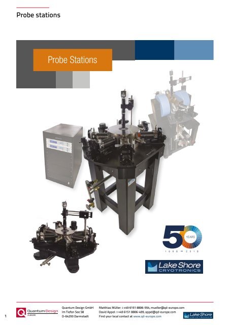
Probe <strong>stations</strong><br />
Probe Stations<br />
YEARS<br />
1 9 6 8 2 0 1 8<br />
1<br />
Quantum Design GmbH<br />
Im Tiefen See 58<br />
D-64293 Darmstadt<br />
Matthias Müller: +49 6151 8806-554, mueller@qd-europe.com<br />
David Appel: +49 6151 8806-499, appel@qd-europe.com<br />
Find your local contact at www.qd-europe.com
Probe <strong>stations</strong><br />
Probe <strong>stations</strong><br />
Supporting advanced research since 1968,<br />
<strong>Lake</strong> <strong>Shore</strong> (www.lakeshore.com) is a leading<br />
innovator in measurement and control solutions<br />
for materials characterization under extreme<br />
temperature and magnetic field conditions.<br />
High-performance product solutions from<br />
<strong>Lake</strong> <strong>Shore</strong> include cryogenic temperature<br />
sensors and instrumentation, magnetic test<br />
and measurement systems, <strong>probe</strong> <strong>stations</strong>, and<br />
precision materials characterizations systems that<br />
explore the electronic and magnetic properties<br />
of next-generation materials. <strong>Lake</strong> <strong>Shore</strong><br />
serves an international base of customers at<br />
leading university, government, aerospace, and<br />
commercial research institutions and is supported<br />
by a global network of sales and service facilities.<br />
Contents<br />
Family overview .................................................................4–5<br />
Applications overview ..........................................................6<br />
Research examples ...............................................................7<br />
Hall system integration .......................................................8<br />
THz on-wafer probing ..........................................................2<br />
Unique configurations .........................................................9<br />
Variable temperature solutions ......................10–11<br />
Accurate sample temperature is key .............12–13<br />
Systems overview ............................................................... 14<br />
Features by model.............................................................. 14<br />
Initial cost/cryogen cost comparison .................. 15<br />
Probing configurations ..........................................16–21<br />
Sample holders...........................................................22–23<br />
Vision system ...............................................................24–25<br />
Installed options ................................................................... 26<br />
Field installable options .......................................27–29<br />
TTPX ....................................................................................30–31<br />
CPX ......................................................................................32–33<br />
CPX-VF ..............................................................................34–35<br />
EMPX-H2 .........................................................................36–37<br />
FWPX ..................................................................................38–39<br />
CRX-6.5K ........................................................................40–41<br />
CRX-4K .............................................................................42–43<br />
CRX-VF ..............................................................................44–45<br />
CRX-EM-HF ...................................................................46–47<br />
Ordering information ..............................................48–49<br />
Equipment compatibility ......................................50–51<br />
How to configure a <strong>probe</strong> station ........................... 52<br />
<strong>Lake</strong> <strong>Shore</strong>’s cryogenic <strong>probe</strong> <strong>stations</strong> provide precisely controlled<br />
environments for non-destructive measurement of the electrical<br />
properties of materials and early-stage electronic devices.<br />
Probe <strong>stations</strong> enable physical scientists and researchers to conduct<br />
fundamental science through convenient, repeatable measurements<br />
producing consistent results. Probe <strong>stations</strong> are versatile and flexible<br />
research platforms that can be used in dedicated applications or as<br />
multi-use community research assets.<br />
Typical applications include sampling I-V and C-V curves over a wide<br />
range of temperatures, measuring microwave and electro-optical<br />
responses, characterizing magneto-transport properties in variable<br />
magnetic fields, Hall effect measurements to understand carrier<br />
mobility, and a variety of other material studies.<br />
p. 3<br />
<strong>Lake</strong> <strong>Shore</strong> <strong>Cryotronics</strong>, Inc. | t. 614.891.2243 | f. 614.818.1600 | info@lakeshore.com | www.lakeshore.com<br />
p. 2<br />
<strong>Lake</strong> <strong>Shore</strong> <strong>Cryotronics</strong>, Inc. | t. 614.891.2243 | f. 614.818.1600 | info@lakeshore.com | www.lakeshore.com<br />
Quantum Design GmbH Matthias Müller: +49 6151 8806-554, mueller@qd-europe.com<br />
Im Tiefen See 58<br />
David Appel: +49 6151 8806-499, appel@qd-europe.com<br />
2 D-64293 Darmstadt Find your local contact at www.qd-europe.com<br />
3<br />
Quantum Design GmbH<br />
Im Tiefen See 58<br />
D-64293 Darmstadt<br />
Matthias Müller: +49 6151 8806-554, mueller@qd-europe.com<br />
David Appel: +49 6151 8806-499, appel@qd-europe.com<br />
Find your local contact at www.qd-europe.com
Probe <strong>stations</strong><br />
Probe <strong>stations</strong><br />
Cryogenic Probe Stations<br />
Cryogen-Free Probe Stations<br />
Available with<br />
integrated Hall<br />
measurement<br />
Selection, precision, versatility<br />
<strong>Lake</strong> <strong>Shore</strong>’s family of precision<br />
cryogenic <strong>probe</strong> <strong>stations</strong> offers<br />
numerous environmental and<br />
probing choices to meet the<br />
diverse application needs of<br />
researchers. From general purpose<br />
units to specialized platforms, each<br />
<strong>probe</strong> station is carefully designed<br />
to ensure stable operation and<br />
dependable measurements from<br />
cryogenic temperatures all the way<br />
through the operating range.<br />
Cryogen-free platforms offer<br />
customers the convenience of<br />
push-button operation, while liquid<br />
cryogen-based <strong>stations</strong> provide<br />
a lower initial cost for those who<br />
are comfortable working with<br />
traditional liquid cryogens. Magnetequipped<br />
models enable the study<br />
of material responses in fields up<br />
to as high as ±2.5 T. Applicationspecific<br />
configurations including<br />
high vacuum, load-lock, high<br />
temperature, and larger sample<br />
sizes are offered on certain models.<br />
All <strong>Lake</strong> <strong>Shore</strong> <strong>probe</strong> <strong>stations</strong><br />
include unique thermal design<br />
features to ensure the highest<br />
possible confidence when<br />
recording sample temperatures.<br />
High-precision micro-manipulated<br />
<strong>probe</strong> stages and a variety of<br />
<strong>probe</strong> tip options ensure accurate<br />
tip placement across a wide<br />
range of sample types. And, with<br />
our patented ZN50R-CVT <strong>probe</strong>,<br />
stable tip position is assured,<br />
making convenient unattended<br />
measurements possible over<br />
continuously variable temperatures.<br />
Need automated or largerwafer<br />
probing?<br />
Contact <strong>Lake</strong> <strong>Shore</strong> sales. We<br />
can recommend a <strong>probe</strong> station<br />
that supports full-wafer probing<br />
and features automated stages<br />
for replicating measurements<br />
across many wafer devices.<br />
p. 4<br />
<strong>Lake</strong> <strong>Shore</strong> <strong>Cryotronics</strong>, Inc. | t. 614.891.2243 | f. 614.818.1600 | info@lakeshore.com | www.lakeshore.com<br />
p. 5<br />
<strong>Lake</strong> <strong>Shore</strong> <strong>Cryotronics</strong>, Inc. | t. 614.891.2243 | f. 614.818.1600 | info@lakeshore.com | www.lakeshore.com<br />
Quantum Design GmbH Matthias Müller: +49 6151 8806-554, mueller@qd-europe.com<br />
Im Tiefen See 58<br />
David Appel: +49 6151 8806-499, appel@qd-europe.com<br />
4 D-64293 Darmstadt Find your local contact at www.qd-europe.com<br />
5<br />
Quantum Design GmbH<br />
Im Tiefen See 58<br />
D-64293 Darmstadt<br />
Matthias Müller: +49 6151 8806-554, mueller@qd-europe.com<br />
David Appel: +49 6151 8806-499, appel@qd-europe.com<br />
Find your local contact at www.qd-europe.com
Probe <strong>stations</strong><br />
Probe <strong>stations</strong><br />
Applications overview<br />
<strong>Lake</strong> <strong>Shore</strong> <strong>probe</strong> <strong>stations</strong> are well suited for a broad range of material characterization and measurement applications.<br />
The table below lists several of these applications and indicates where each <strong>probe</strong> station is a good fit (orange) or has<br />
been specifically designed for this purpose (star).<br />
I-V<br />
C-V<br />
Cryogenic <strong>probe</strong> <strong>stations</strong><br />
Cryogen-free <strong>probe</strong> <strong>stations</strong><br />
TTPX CPX CPX-VF EMPX-H2 FWPX CRX-6.5K CRX-4K CRX-VF CRX-EM-HF<br />
Microwave <br />
Electro-optical <br />
Magneto-transport (MT) <br />
Vector dependent MT <br />
Hall effect measurement<br />
** ** ** ** **<br />
Organics <br />
Controlled sample transport <br />
Large wafer*<br />
<br />
Research examples<br />
Superconducting RF MEMS filter design<br />
A novel superconducting RF MEMS switch<br />
is implemented in a capacitor bank to realize<br />
different capacitance values. The capacitor bank<br />
is monolithically integrated to a shunt bandstop<br />
resonator. Figure 1 shows the circuit model of<br />
the tunable resonator. The resonator consists of<br />
a lumped element spiral inductor in series with<br />
a switched capacitor bank. Figure 2 illustrates a<br />
picture of the monolithically integrated bandstop<br />
resonator with the capacitor bank. The dimension<br />
of the device is 2.7 mm × 1.3 mm, which is<br />
extremely miniaturized for a high quality factor<br />
tunable resonator. The tunable resonator is<br />
measured in the <strong>Lake</strong> <strong>Shore</strong> cryogenic <strong>probe</strong><br />
station using two ground-signal-ground (GSG)<br />
<strong>probe</strong>s. Figure 3 shows the measured results of<br />
the three states of the tunable resonator at 4 K.<br />
The resonance frequency is initially at 1.107 GHz<br />
when all the switches are off (state I); then shifts<br />
to 1.057 GHz and 1.025 GHz when the first and<br />
the second switches are on, respectively.<br />
Raafat R. Mansour, Ph.D, Professor<br />
Electrical and Computer Engineering Department<br />
University of Waterloo<br />
Figure 2<br />
Figure 1<br />
Figure 3<br />
= Recommended for = Is capable of<br />
* For probing wafers larger than 102 mm or 152 mm, contact <strong>Lake</strong> <strong>Shore</strong><br />
** Limited Hall effect measurements possible with 0.2 T ring magnet installed<br />
Applications<br />
Nanoelectronics<br />
Magnetism & spintronics<br />
Organic & molecular electronics<br />
Semiconductors<br />
Optoelectronics<br />
Microwave electronics<br />
Quantum devices<br />
Superconductors<br />
MEMS/NEMS<br />
Low noise RF<br />
Ferrolectrics<br />
Thin films<br />
IR detectors<br />
DLTS/DLOS to measure defects in semiconductor devices<br />
Deep level transient spectroscopy (DLTS) is a powerful<br />
technique to measure defects in semiconductors and<br />
interfaces in a variety of devices. For wide bandgap-based<br />
devices, deep level optical spectroscopy (DLOS) enables<br />
probing deeper than the thermal limit of ~1 eV and probing<br />
of traps in the minority carrier half of the bandgap. These<br />
techniques are traditionally performed on Schottky or<br />
p-n junctions, but can also be applied to metal-insulatorsemiconductor<br />
capacitors (MISCaps) to accurately quantify<br />
interface state densities throughout the interface bandgap.<br />
Figure 1 shows a typical structure for measuring interface<br />
states and Fig. 2 shows the results of the thermal and<br />
optical DLTS/DLOS scans of the sample in Fig. 1. The<br />
interface states are shown directly correlate with frequency<br />
dispersion and can cause a number of performance related<br />
issues (leakage pathways, transient threshold voltage shifts,<br />
noise, etc.) in typical devices.<br />
The <strong>Lake</strong> <strong>Shore</strong> cryogenic stages allow scanning the<br />
temperature over a wide range, ideal for DLTS, and provides<br />
easy optical access to shine monochromatic light on the<br />
samples for DLOS. Customized for our application, the<br />
<strong>probe</strong>s allow scanning hundreds of degrees Kelvin without<br />
contacts slipping and without destroying delicate contacts<br />
(something not possible in many cryogenic stages).<br />
Aaron Arehart, Ph.D, Professor<br />
Electrical and Computer Engineering Department<br />
The Ohio State University<br />
Figure 1: Metal-insulator-semiconductor<br />
structure for analyzing interface state<br />
densities at the insulator-semiconductor<br />
interface, specifically the atomic layer<br />
deposition (ALD)-grown Al 2 O 3 /n-type<br />
NH 3 -MBE-grown GaN interface is<br />
quantified using deep level transient and<br />
optical spectroscopies (DLTS/DLOS).<br />
Figure 2: Interface state<br />
density (D it ) at the ALD Al 2 O 3 /<br />
GaN interface in Figure 1 is<br />
shown using thermally-based<br />
DLTS for states within 0.8 eV<br />
of the GaN conduction band<br />
and optically stimulated<br />
emission-based DLOS using a<br />
xenon (Xe) lamp for mid-gap<br />
to GaN valence band.<br />
p. 6<br />
<strong>Lake</strong> <strong>Shore</strong> <strong>Cryotronics</strong>, Inc. | t. 614.891.2243 | f. 614.818.1600 | info@lakeshore.com | www.lakeshore.com<br />
p. 7<br />
<strong>Lake</strong> <strong>Shore</strong> <strong>Cryotronics</strong>, Inc. | t. 614.891.2243 | f. 614.818.1600 | info@lakeshore.com | www.lakeshore.com<br />
Quantum Design GmbH Matthias Müller: +49 6151 8806-554, mueller@qd-europe.com<br />
Im Tiefen See 58<br />
David Appel: +49 6151 8806-499, appel@qd-europe.com<br />
6 D-64293 Darmstadt Find your local contact at www.qd-europe.com<br />
7<br />
Quantum Design GmbH<br />
Im Tiefen See 58<br />
D-64293 Darmstadt<br />
Matthias Müller: +49 6151 8806-554, mueller@qd-europe.com<br />
David Appel: +49 6151 8806-499, appel@qd-europe.com<br />
Find your local contact at www.qd-europe.com
Probe <strong>stations</strong><br />
Probe <strong>stations</strong><br />
Order a CRX-VF station with an integrated Hall measurement system<br />
Typical Hall contacts<br />
eliminated by CRX-VF<br />
For non-destructive Hall measurement of wafer-scale materials in a<br />
tightly controlled probing environment<br />
The <strong>Lake</strong> <strong>Shore</strong> PS-HM-8425 package enables you to add all<br />
of the DC Hall measurement capabilities of our 8400 Series<br />
Hall system to your CRX-VF <strong>probe</strong> station.<br />
The package includes all the instrumentation and data<br />
acquisition/analysis software for performing Hall voltage,<br />
Hall coefficient, Hall mobility, resistance, I-V curve, and<br />
other measurements. Use the system to identify carriers of<br />
materials by their excitation energies and gain an understanding of dominating<br />
mechanisms, whether for Hall bar geometries or for performing gated Hall bar<br />
measurements.<br />
The system is ideal for measuring multilayer Hall structures as part of device<br />
development as well as probing minute Hall structures that are prone to<br />
contamination, reactive to air, or might require initial warming to drive out<br />
moisture. And because <strong>probe</strong>s are used for Hall measurements, there is no need<br />
to attach wires to the sample (as required in a conventional Hall measurement<br />
system). Also, you can <strong>probe</strong> full or partial wafers up to 51 mm (2 in) in diameter,<br />
eliminating the need to dice fabricated wafers.<br />
For more information, see page 44.<br />
To see more specifications and other details, go to www.lakeshore.com.<br />
NEW M81-SSM Source Measure System<br />
The MeasureReady M81-SSM (Synchronous Source and<br />
Measure) system provides a confident and straightforward<br />
approach for advanced measurement applications. The M81<br />
is designed to eliminate the complexity of multiple functionspecific<br />
instrumentation setups, combining the convenience of<br />
DC and AC sourcing with DC and AC measurement, including a<br />
lock-in’s sensitivity and measurement performance.<br />
This extremely low-noise simultaneous source and measure<br />
system ensures inherently synchronized measurements from<br />
1 to 3 source channels and from 1 to 3 measure channels per<br />
half-rack instrument — while also being highly adaptable for a<br />
range of material and device research applications.<br />
Learn more at www.lakeshore.com/m81<br />
CRX-VF with Hall<br />
measurement package<br />
Direct and derived Direct measurements<br />
and derived measurements<br />
as a function of as field a function and temperature of field and temperature<br />
Hall voltage Hall voltage<br />
I-V curve measurements I-V curve measurements<br />
Resistance Resistance<br />
Magnetoresistance Magnetoresistance<br />
Magnetotransport Magnetotransport<br />
Hall coefficient Hall coefficient<br />
Hall mobility Hall mobility<br />
Anomalous Hall Anomalous effect (AHE) Hall effect (AHE)<br />
Carrier type/concentration/density<br />
Carrier type/concentration/density<br />
Van der Pauw Van and der Hall Pauw bar structures and Hall bar structures<br />
An innovative instrument<br />
architecture optimized to<br />
provide synchronous DC, AC,<br />
and mixed DC+AC source<br />
and measure to 100 kHz for<br />
low‐level measurements<br />
Unique real-time sampling architecture<br />
for synchronous sourcing and measuring<br />
Ideal for scientific-grade low-level<br />
measurement applications<br />
The absolute precision of DC plus the<br />
detection sensitivity performance of AC<br />
instrumentation<br />
Remote-mountable modules are<br />
interchangeable between instruments<br />
Unique configurations possible<br />
Thanks to Elliot Scientific in the U.K., for calling this to our<br />
attention: an interesting <strong>Lake</strong> <strong>Shore</strong> CRX <strong>probe</strong> station<br />
configuration, one that has a spectrophotometer integrated<br />
into its design. This customized <strong>probe</strong> station, installed<br />
at the University of Southampton’s Centre for Photonic<br />
Metamaterials, features an integrated CRAIC Technologies<br />
InGaAs Spectrophotometer and Zeiss microscope. In this<br />
setup, researchers are able to observe optical properties of<br />
nanostructured materials at cryogenic temperatures. Elliot<br />
Scientific, who is quite knowledgeable of both <strong>Lake</strong> <strong>Shore</strong><br />
and CRAIC products, was able to offset mount a Zeiss<br />
microscope carrying the spectrophotometer onto the <strong>probe</strong><br />
station. A dished lid was added to allow the station’s use<br />
with the spectrophotometer, and the microscope uses a<br />
custom-manufactured rig to provide smooth movement in<br />
three axes above the sample chamber. The <strong>probe</strong> station<br />
offers conventional top-side illumination down the axis of the<br />
microscope, but for this setup, the station was also adapted<br />
to provide sample illumination from the side, with the light<br />
then directed upward using a 45° mirror under the sample<br />
holder to provide illumination to the back of the sample.<br />
For more information about what <strong>Lake</strong> <strong>Shore</strong> and our<br />
international representatives can do to help you outfit a<br />
<strong>probe</strong> station for a specialized application, please contact us<br />
at sales@lakeshore.com.<br />
<strong>Lake</strong> <strong>Shore</strong> <strong>probe</strong> <strong>stations</strong> can be adapted in other ways,<br />
too. Custom configurations have been provided for:<br />
• A CRX-EM-HF built to allow for the mounting of a<br />
pivoting and articulating microscope-based system<br />
analyzer head at the top for the visualization and<br />
analysis of micro structures; this design necessitated<br />
the use of a dished lid and custom radiation shield<br />
assembly to reduce Z-axis travel.<br />
• A CRX-VF <strong>probe</strong> station adapted to allow for the<br />
connection of a load-lock arm to a deposition<br />
system, a design that allows the user to<br />
mechanically move a sample from the deposition<br />
system to the station and back without breaking<br />
vacuum.<br />
• A CPX <strong>probe</strong> station with a modified load lock<br />
sample transfer chamber that enables university<br />
researchers to easily move sensitive wafer samples<br />
from an inert gas glovebox via the sample-transfer<br />
“suitcase” to the station’s chamber without exposing<br />
them to the air. See page 26 for the suitcase<br />
option.<br />
p. 8<br />
<strong>Lake</strong> <strong>Shore</strong> <strong>Cryotronics</strong>, Inc. | t. 614.891.2243 | f. 614.818.1600 | info@lakeshore.com | www.lakeshore.com<br />
p. 9<br />
<strong>Lake</strong> <strong>Shore</strong> <strong>Cryotronics</strong>, Inc. | t. 614.891.2243 | f. 614.818.1600 | info@lakeshore.com | www.lakeshore.com<br />
Quantum Design GmbH Matthias Müller: +49 6151 8806-554, mueller@qd-europe.com<br />
Im Tiefen See 58<br />
David Appel: +49 6151 8806-499, appel@qd-europe.com<br />
8 D-64293 Darmstadt Find your local contact at www.qd-europe.com<br />
9<br />
Quantum Design GmbH<br />
Im Tiefen See 58<br />
D-64293 Darmstadt<br />
Matthias Müller: +49 6151 8806-554, mueller@qd-europe.com<br />
David Appel: +49 6151 8806-499, appel@qd-europe.com<br />
Find your local contact at www.qd-europe.com
Probe <strong>stations</strong><br />
Probe <strong>stations</strong><br />
Software solutions for variable temperature measurements<br />
Using a Keysight B1500A semiconductor device parameter analyzer to automate measurements<br />
Keysight B1500A<br />
With the B1500A analyzer connected to a <strong>Lake</strong> <strong>Shore</strong> cryogenic<br />
<strong>probe</strong> station, you can efficiently <strong>probe</strong> early-stage devices and<br />
materials, then you can initiate the software to run a diverse set of<br />
parameter measurements over a range of temperatures while you<br />
attend to other matters. EasyExpert takes care of the measurements<br />
and coordinates seamlessly with the Model 336 to precisely record<br />
and control sample temperatures throughout the run.<br />
Convenient operation, reliable measurements, more productivity.<br />
Take control of your research with this integrated solution<br />
from Keysight and <strong>Lake</strong> <strong>Shore</strong>.<br />
Reliable measurements in less time. It’s what every material researcher<br />
strives for. Now precise characterization of early-stage materials and devices<br />
over wide temperature ranges is made even more convenient—thanks to a<br />
collaboration between Keysight Technologies and <strong>Lake</strong> <strong>Shore</strong> <strong>Cryotronics</strong><br />
that links our respective products.<br />
An interface to <strong>Lake</strong> <strong>Shore</strong> <strong>probe</strong> <strong>stations</strong>’ cryogenic temperature controller<br />
(Model 336) enables researchers using Keysight’s powerful B1500A<br />
semiconductor device parameter analyzer and its EasyExpert software to<br />
programmatically manage<br />
temperature settings<br />
while making automated<br />
measurements.<br />
Using a Radiant system to rapidly characterize ferroelectric devices<br />
Ferroelectric materials are used in a wide variety of applications, including<br />
sensors, ferroelectric memory (FeRAM), MEMs devices, actuators, and<br />
photovoltaics. Rapid assessment of ferroelectric device characteristics is<br />
critical to improving ferroelectric materials processing as well as developing<br />
accurate ferroelectric device models. The combination of Radiant ferroelectric<br />
test solutions and <strong>Lake</strong> <strong>Shore</strong> <strong>probe</strong> <strong>stations</strong> offers researchers a flexible<br />
platform to efficiently characterize multiple devices in a cryogenic probing<br />
environment. The addition of cryogenic temperature characterization can<br />
open new frontiers to understanding dielectric<br />
properties, switching mechanisms, and fatigue in<br />
ferroelectric materials.<br />
Measurements include:<br />
• Hysteresis vs. temperature<br />
• Leakage vs. temperature<br />
• Hysteresis speed vs. temperature<br />
• Remanent hysteresis vs. temperature<br />
• PUND remanent polarization vs.<br />
temperature<br />
• PUND frequency response vs. temperature<br />
• Breakdown voltage vs. temperature<br />
• I-V vs. temperature<br />
• C-V vs. temperature<br />
• Fatigue vs. temperature<br />
• Retention vs. temperature<br />
• Imprint vs. temperature<br />
Probing environment<br />
<strong>Lake</strong> <strong>Shore</strong> cryogenic <strong>probe</strong> <strong>stations</strong> are versatile and flexible research<br />
platforms which provide precisely controlled environments for nondestructive<br />
measurement of the electrical properties of materials and<br />
electronic devices. When combined with <strong>Lake</strong> <strong>Shore</strong>’s patented continuously<br />
variable temperature (CVT) <strong>probe</strong>s, true unattended wafer probing of a device<br />
across a range of temperatures is achieved. The CVT <strong>probe</strong> design absorbs<br />
<strong>probe</strong> arm movement caused by thermal expansion and contraction, resulting<br />
in a stable <strong>probe</strong> tip landing position throughout variable temperature cycling.<br />
Remanent hysteresis vs. temperature—40,000 µm 2 20/80<br />
PZT measured in a <strong>Lake</strong> <strong>Shore</strong> CRX-4K <strong>probe</strong> station<br />
Using a Keithley 4200-SCS parameter analyzer to automate measurements<br />
Many <strong>Lake</strong> <strong>Shore</strong> customers use stand-alone instrumentation and automation software<br />
to control <strong>probe</strong> station measurements. But we’re also seeing others using the integrated<br />
programming interface of Keithley’s 4200-SCS Parameter Analyzer system to automate<br />
the running of variable temperature measurements in a <strong>Lake</strong> <strong>Shore</strong> <strong>probe</strong> station with our<br />
patented ZN50R-CVT <strong>probe</strong>s.<br />
This can be quite a time-saver, especially when measuring I-V curves or sheet resistance<br />
at various temperatures. Instead of having to set the sample stage temperature, wait<br />
for the sample temperature to stabilize, and perform one or more device measurements<br />
before moving on to the next temperature, you can program the system to step through<br />
temperature settings and run a number of measurements over a range of temperatures<br />
without repeated user intervention.<br />
This programmatic capability is integrated into<br />
the 4200-SCS system because Keithley’s latest<br />
firmware release includes a driver for the <strong>Lake</strong><br />
<strong>Shore</strong> Model 336, the instrument that controls<br />
the <strong>probe</strong> station sample stage temperature. It<br />
can be particularly helpful, for example, when<br />
characterizing transistor devices at various<br />
temperatures.<br />
1. 336 initialization<br />
2. Sets temperature<br />
and reads stage<br />
temperature until it<br />
reaches setpoint<br />
3. Performs device<br />
measurement<br />
Keithley 4200-SCS<br />
Easy interface<br />
<strong>Lake</strong> <strong>Shore</strong> <strong>probe</strong> <strong>stations</strong> easily interface with Radiant Technologies, Inc.<br />
Ferroelectric/Multiferroic Test Systems to provide fast and accurate testing of<br />
ferroelectric and piezoelectric materials as a function of temperature.<br />
Easy programming<br />
Radiant’s data acquisition program executes automated tests of single<br />
samples over a wide temperature range, making long duration testing<br />
effortless.<br />
Combined with a <strong>Lake</strong> <strong>Shore</strong> <strong>probe</strong> station and Model 336 controller,<br />
temperature setpoints can be pre-programmed. The software can be<br />
configured for different measurements and generate multiple plots at the<br />
touch of a button. These plots (in a single pass on a single sample) include<br />
but are not limited to:<br />
• Measure and plot hysteresis<br />
• Remanent polarization<br />
• Leakage<br />
• Small signal capacitance<br />
• Thermally engineer ferroelectric components<br />
• Set variable temperature measurements<br />
• Measure phase boundaries<br />
• Measure coercive voltage changes<br />
• Measure switching speeds<br />
• Measure device leakage<br />
Vision data acquisition software enables plotting of<br />
multiple temperature measurements as well as custom<br />
programming to create your own test profile<br />
USB<br />
Computer<br />
Radiant Precision Ferroelectric Tester<br />
DRIVE (BNC)<br />
<strong>Lake</strong> <strong>Shore</strong> Model 336 Controller<br />
<strong>Lake</strong> <strong>Shore</strong> Probe Station<br />
DRIVE<br />
Capacitor device<br />
Isolated sample<br />
holder<br />
Sample stage<br />
RETURN (BNC)<br />
RETURN<br />
Ground plane<br />
GPIB<br />
Contact us so we can configure the right <strong>probe</strong> station and precision<br />
test platform for your application—supplied jointly with Radiant.<br />
<strong>Lake</strong> <strong>Shore</strong> cryogenic chamber and Radiant’s test system<br />
easily interface. Vision software controls the <strong>Lake</strong> <strong>Shore</strong><br />
unit via the <strong>Lake</strong> <strong>Shore</strong> Model 336 temperature controller.<br />
p. 10<br />
<strong>Lake</strong> <strong>Shore</strong> <strong>Cryotronics</strong>, Inc. | t. 614.891.2243 | f. 614.818.1600 | info@lakeshore.com | www.lakeshore.com<br />
p. 11<br />
<strong>Lake</strong> <strong>Shore</strong> <strong>Cryotronics</strong>, Inc. | t. 614.891.2243 | f. 614.818.1600 | info@lakeshore.com | www.lakeshore.com<br />
Quantum Design GmbH Matthias Müller: +49 6151 8806-554, mueller@qd-europe.com<br />
Im Tiefen See 58<br />
David Appel: +49 6151 8806-499, appel@qd-europe.com<br />
10 D-64293 Darmstadt Find your local contact at www.qd-europe.com<br />
11<br />
Quantum Design GmbH<br />
Im Tiefen See 58<br />
D-64293 Darmstadt<br />
Matthias Müller: +49 6151 8806-554, mueller@qd-europe.com<br />
David Appel: +49 6151 8806-499, appel@qd-europe.com<br />
Find your local contact at www.qd-europe.com
Probe <strong>stations</strong><br />
Probe <strong>stations</strong><br />
The accuracy of your sample temperature is key<br />
Cryogenic measurements of devices in conventional cryostats typically require time-consuming and destructive wiring of an onwafer<br />
device. That isn’t the case with cryogenic <strong>probe</strong> <strong>stations</strong>. These platforms enable visualization and electrical interrogation<br />
of multiple wafer-level devices using positionable <strong>probe</strong>s, accelerating characterization efforts. The tradeoff for optical access<br />
to and flexible probing of the device under test lies in the heat loads from thermal radiation and <strong>probe</strong> arm heat conduction via<br />
the <strong>probe</strong> arms. Because of these loads, as well as the thermal resistance between the device and sample stage, the actual<br />
temperature of the device can deviate from the sample stage sensor — leading to inaccurate measurements.<br />
To minimize this effect, the <strong>probe</strong> station should have radiation shields to reduce the thermal radiation on the sample and the<br />
<strong>probe</strong>s should be thermally anchored at or near the sample stage (see the next page for how our <strong>stations</strong> are designed this way).<br />
Below, we examine the role of <strong>probe</strong> arm thermal anchoring in relationship to device temperature, specifically when attempting<br />
to quickly evaluate superconducting circuits, a common application for cryogenic measurements of electronic devices.<br />
Determining conductive heat transfer in a <strong>probe</strong> station using Cernox ® and niobium wire reference measurements<br />
How our <strong>stations</strong> keep heat from reaching the sample<br />
<strong>Lake</strong> <strong>Shore</strong>’s <strong>probe</strong> <strong>stations</strong> take thermal management to the next level, providing a<br />
measurement platform you can really trust.<br />
Thermal <strong>probe</strong> anchoring <strong>Lake</strong> <strong>Shore</strong> <strong>probe</strong> <strong>stations</strong> include special thermal anchoring<br />
to throttle unwanted heat sources. In <strong>probe</strong> <strong>stations</strong> without comprehensive thermal<br />
anchoring, the device under test may be much warmer than the sample stage itself<br />
(and of unknown temperature). Reporting device temperatures based only on a<br />
sample stage sensor where heat loads are not controlled can lead to erroneous<br />
results. Precise device characterization requires a good understanding of the<br />
device’s actual temperature. To avoid injecting unwanted heat into the sample device<br />
via the <strong>probe</strong> arms, the arms and <strong>probe</strong>s must be thermally anchored.<br />
Temperature sensors <strong>Lake</strong> <strong>Shore</strong> <strong>probe</strong>s are cooled to the sample stage temperature<br />
to minimize heat load to the device under test. <strong>Lake</strong> <strong>Shore</strong> sensors on the sample<br />
stage, <strong>probe</strong> arm, and radiation shield provide an accurate thermal profile of the test<br />
environment.<br />
Arm<br />
base<br />
Probe arm<br />
thermal anchor<br />
to radiation<br />
shield stage<br />
Probe thermal<br />
anchor to<br />
sample stage<br />
Probe arm<br />
Temperature sensor<br />
Probe<br />
Sample stage<br />
Radiation shield stage<br />
Vacuum chamber base<br />
The thermal anchors in <strong>Lake</strong> <strong>Shore</strong> <strong>probe</strong> <strong>stations</strong><br />
(shown above in the TTPX) increase sample<br />
temperature accuracy<br />
Four point probing of a Cernox reference device<br />
using a CRX-4K <strong>probe</strong> station<br />
Experimental setup<br />
To investigate the role<br />
of <strong>probe</strong> arm thermal<br />
anchoring on the<br />
device temperature in a<br />
cryogenic measurement,<br />
a <strong>Lake</strong> <strong>Shore</strong> CRX-4K<br />
<strong>probe</strong> station with a fixed<br />
1 W sample stage cooling<br />
capacity was chosen<br />
as the test platform. For<br />
simulating a device under<br />
test, a calibrated Cernox ®<br />
sensor was soldered onto<br />
a sapphire substrate, with<br />
its underside coated with a thin layer of Apiezon ® N grease and clamped to<br />
a 32 mm (1.25 in) grounded sample holder. Tungsten tips (25 µm diameter)<br />
on four <strong>probe</strong> arms were landed on the contact pads of the sensor, and<br />
the device temperature was obtained with our Model 336 temperature<br />
controller using a four-point probing measurement of sensor resistance.<br />
Additional temperature sensors within each of the four arms and one bolted<br />
to the underside of the sample stage were used to monitor arm and stage<br />
temperatures.<br />
Results<br />
Table 1 summarizes the device, stage, and arm temperatures for three<br />
common <strong>probe</strong> arm thermal anchoring configurations. In the recommended<br />
configuration, the arm is anchored to the radiation shield and the <strong>probe</strong> is<br />
anchored to the sample stage (as shown in the diagram on the next page).<br />
The second configuration relies solely on thermally anchoring both the arm<br />
and the <strong>probe</strong>s to the shield, and the final configuration consists of four<br />
unanchored arms and the shielding removed.<br />
Table 1—Configuration dependent device temperature<br />
Probing configuration<br />
Sample stage<br />
temp (K)<br />
Mean arm<br />
temp (K)<br />
Device temp<br />
(K)<br />
Arms anchored to radiation shield, 4.87 9.21 7.57<br />
<strong>probe</strong>s to sample stage<br />
Arms anchored to radiation shield 3.80 34.94 12.13<br />
Arms not anchored, no radiation shield 6.46 271.7 41.16<br />
In the first configuration, the thermal load on the station’s cooling stage<br />
is increased by anchoring the <strong>probe</strong>s to the sample stage, resulting in a<br />
higher sample stage temperature than in the second configuration with the<br />
<strong>probe</strong>s anchored to the radiation shield. However, the lower sample stage<br />
temperature does not translate into a lower device temperature as the extra<br />
conductive heat load from the <strong>probe</strong>s is not compensated by the additional<br />
cooling through the device substrate. Despite the relatively small impact on<br />
stage temperature by removing the radiation shield and <strong>probe</strong>/<strong>probe</strong> arm<br />
thermal anchors, the third configuration causes a substantial increase in heat<br />
load to the device, driving up the device temperature by more than 30 K.<br />
Discussion<br />
Using well-anchored <strong>probe</strong>s and <strong>probe</strong> arms, we demonstrate the ability<br />
to rapidly evaluate superconducting circuits. For this measurement, a small<br />
wire was cut from a 99.8% pure niobium foil (Alfa-Aesar ® ) and affixed to<br />
a sapphire plate with a thin layer of cyanoacrylate adhesive. The wire was<br />
then thinned to increase the contrast in resistance between normal and<br />
superconducting states; the thinned niobium wire has a 272 mΩ resistance<br />
at room temperature. The sapphire substrate was mounted in an identical<br />
fashion to the Cernox reference chip, then cooled to cryogenic temperatures<br />
in the station. After landing four <strong>probe</strong>s directly on the niobium wire, the wire<br />
resistance was monitored as a function of stage temperature with our Model<br />
370 AC resistance bridge equipped with a 3708 pre-amplifier. At each stage<br />
temperature setpoint, the system was allowed to stabilize for 5 min prior to<br />
acquiring a device resistance.<br />
Superconducting transition in a <strong>probe</strong>d<br />
niobium wire<br />
Conclusion<br />
The figure at left shows the<br />
wire resistance as a function<br />
of stage temperature,<br />
indicating a sharp decrease<br />
in the wire resistance at stage<br />
temperatures below 8.90 K,<br />
which we attribute to the onset<br />
of superconductivity in the<br />
<strong>probe</strong>d wire. Below 8.75 K, the<br />
wire resistance drops below the<br />
measurement accuracy of the<br />
experimental setup (
Probe <strong>stations</strong><br />
Probe <strong>stations</strong><br />
Systems overview<br />
<strong>Lake</strong> <strong>Shore</strong>’s family of cryogenic <strong>probe</strong> <strong>stations</strong> includes entry-level models and advanced feature models. Choose<br />
from conventional liquid cryogen cooling models (shown in blue) or convenient cryogen-free cooling (shown in orange).<br />
Equivalent models in cryogenic and cryogen-free configurations are joined by a dotted line.<br />
EMPX-H2<br />
CRX-EM-HF<br />
Cryogen or cryogen free: which one is right for you?<br />
For users seeking alternatives to traditional (‘wet’) cryogenic <strong>probe</strong> <strong>stations</strong>, <strong>Lake</strong> <strong>Shore</strong> offers ‘dry’ platforms: closedcycle<br />
refrigeration (CCR) based <strong>stations</strong> that provide efficient temperature operation and control while eliminating the<br />
operating expense of liquid cryogens. If you are concerned about price volatility in the liquid helium (LHe) supply market,<br />
a CCR-based station may be right for you.<br />
Initial cost / operating cost comparison<br />
Liquid cryogen-cooled models offer a lower initial platform cost. Operating costs are largely dependent upon LHe costs,<br />
which vary by region and often by season.<br />
Specialization<br />
TTPX<br />
CPX<br />
CRX-6.5K<br />
CPX-VF<br />
CRX-4K<br />
FWPX<br />
CRX-VF<br />
= Horizontal field<br />
= Vertical field<br />
Cryogen-free models offer the convenience of closed cycle refrigeration, eliminating ongoing cost of liquid cryogens.<br />
They can often pay for themselves in under three years, depending on prevailing LHe costs.<br />
TTPX<br />
CRX-6.5K<br />
CPX<br />
CRX-4K<br />
CPX-VF<br />
Initital system cost<br />
Operation cost for 3 years with LHe at $10/L<br />
Operation cost for 3 years with LHe at $20/L<br />
Operation cost for 3 years with LHe at $40/L<br />
Probe station features by model<br />
Cryogenfree<br />
Magnetic<br />
field<br />
Pneumatic<br />
vibration<br />
isolation<br />
Stand<br />
Cost<br />
<strong>Lake</strong> <strong>Shore</strong>’s <strong>probe</strong> station family features many configuration options to cover the requirements of a broad range of<br />
applications. Use the table below to identify any specific features needed and the <strong>probe</strong> station models that best meet<br />
these needs. The icons below are depicted for reference in the specification pages for each model, starting on page 30.<br />
Configurations — must be ordered with the station Options —<br />
may be added in the field<br />
12:1<br />
microscope<br />
High<br />
vacuum Load-lock†<br />
Very low<br />
temperature<br />
operation<br />
Backside<br />
optical<br />
access<br />
360°<br />
sample<br />
stage<br />
rotation<br />
±5°<br />
sample<br />
stage<br />
rotation<br />
High<br />
temperature<br />
operation<br />
Low<br />
temperature<br />
operation<br />
TTPX* to 675 K to 3.2 K<br />
CPX included to 1.6 K • to 1.9 K<br />
±2.5 T<br />
CPX-VF<br />
included • to 1.9 K<br />
vertical<br />
±0.6 T<br />
EMPX-H2<br />
included to 3.2 K<br />
horizontal<br />
FWPX included included • to 3.5 K<br />
CRX-6.5K • included to 675 K<br />
CRX-4K • included to 675 K<br />
CRX-VF<br />
CRX-EM-HF<br />
free VLT<br />
± 5°<br />
±2.5 T<br />
•<br />
vertical<br />
±0.6 T<br />
•<br />
horizontal<br />
included <br />
included <br />
• = feature inherent to system = feature available blank cell = feature not available<br />
*The TTPX is available in a fully specified, preconfigured tabletop model with four-arm triaxial configuration (PS-100). For details, see page 31.<br />
†<br />
As a field-installable option to the load-lock, a suitcase for controlled sample transport is also available; see page 26.<br />
HT<br />
LT<br />
Add at any<br />
time<br />
Ring<br />
magnet<br />
sample<br />
holder kit<br />
Up to<br />
~0.19 T<br />
Up to<br />
~0.19 T<br />
Up to<br />
~0.19 T<br />
Up to<br />
~0.19 T<br />
CRX-VF<br />
EMPX-H2<br />
CRX-EM-HF<br />
FWPX<br />
Total cost<br />
$100,000 $200,000 $300,000 $400,000<br />
Assuming 2 cooldowns per week at a measurement length of 8 hours for 50 weeks out of the year in a typically-configured 4-arm <strong>probe</strong> station<br />
Cryogen-free conversion path also available<br />
If you already own a <strong>Lake</strong> <strong>Shore</strong> liquid-cooled cryogenic<br />
<strong>probe</strong> station, we offer a convenient path to convert to<br />
dry operation. By doing so, you can preserve your original<br />
investment while eliminating the need to purchase additional<br />
LHe in the future.<br />
Our CCR upgrade allows you to easily upgrade from a<br />
cryogenic <strong>probe</strong> station to a cryogen-free <strong>probe</strong> station.<br />
The program includes an on-site exchange of the base<br />
flow <strong>probe</strong> station for a brand-new base CCR station.<br />
The upgraded station will use the original vision system,<br />
instrumentation, and probing options (such as <strong>probe</strong>s,<br />
cables, and sample holders) as the original <strong>probe</strong> station.<br />
Upgrade path for <strong>Lake</strong> <strong>Shore</strong> <strong>probe</strong> <strong>stations</strong>:<br />
Existing <strong>probe</strong> station<br />
TTPX<br />
CPX<br />
CPX-VF<br />
EMPX(-H2)<br />
with CCR upgrade, becomes<br />
CRX-6.5K<br />
CRX-4K<br />
CRX-VF<br />
CRX-EM-HF<br />
p. 14<br />
<strong>Lake</strong> <strong>Shore</strong> <strong>Cryotronics</strong>, Inc. | t. 614.891.2243 | f. 614.818.1600 | info@lakeshore.com | www.lakeshore.com<br />
p. 15<br />
<strong>Lake</strong> <strong>Shore</strong> <strong>Cryotronics</strong>, Inc. | t. 614.891.2243 | f. 614.818.1600 | info@lakeshore.com | www.lakeshore.com<br />
Quantum Design GmbH Matthias Müller: +49 6151 8806-554, mueller@qd-europe.com<br />
Im Tiefen See 58<br />
David Appel: +49 6151 8806-499, appel@qd-europe.com<br />
14 D-64293 Darmstadt Find your local contact at www.qd-europe.com<br />
15<br />
Quantum Design GmbH<br />
Im Tiefen See 58<br />
D-64293 Darmstadt<br />
Matthias Müller: +49 6151 8806-554, mueller@qd-europe.com<br />
David Appel: +49 6151 8806-499, appel@qd-europe.com<br />
Find your local contact at www.qd-europe.com
Probe <strong>stations</strong><br />
Probe <strong>stations</strong><br />
Probing configurations<br />
Flexible, expandable probing<br />
This comprehensive line of standard micro-manipulated <strong>probe</strong> arms and<br />
accessories to meet a variety of scientific needs. Specific needs of DC,<br />
RF, microwave, and optical probing can be accommodated.<br />
• All <strong>probe</strong>s capable of operation over the full sample stage temperature,<br />
vacuum and magnetic field range of each <strong>probe</strong> station model<br />
• For magnetic field <strong>probe</strong> <strong>stations</strong>, configurations will be non-magnetic<br />
• One sensor is installed wired to a 6-pin feedthrough in arm location #1<br />
standard for all <strong>probe</strong> station models. Optional sensors can be ordered<br />
(PA-SEN) with the purchase of additional <strong>probe</strong> arms (PS-PAB-XX).<br />
Probing configurations and their uses<br />
General purpose DC<br />
High impedance DC<br />
Small signal/low noise DC measurements<br />
High impedance/low current leakage measurements<br />
The ZN50 <strong>probe</strong> base incorporates a pair of copper<br />
braids that anchor to the sample stage to dynamically<br />
cool/heat the <strong>probe</strong> to the sample temperature<br />
Probing configuration specifications<br />
Operation frequency<br />
Electrical<br />
isolation*<br />
Capacitance Impedance S11/S22**<br />
(reflection)<br />
S12/S21**<br />
(transmission)<br />
General purpose DC DC to 50 MHz >100 MΩ 100 GΩ*** 10 MΩ not specified 50 Ω
Probe <strong>stations</strong><br />
Probe <strong>stations</strong><br />
ZN50R-CVT DC/RF flexible <strong>probe</strong>s<br />
Developed in collaboration with TOYO Corporation of<br />
Japan, the patented <strong>Lake</strong> <strong>Shore</strong> Model ZN50R-CVT<br />
automatically compensates for <strong>probe</strong> arm temperature<br />
expansion of thermally anchored <strong>probe</strong>s, significantly<br />
improving measurement reliability and enabling<br />
measurement automation over wide temperature ranges.<br />
Probe model Tip material Tip radius (µm)<br />
ZN50R-CVT-10-W<br />
10<br />
Tungsten<br />
ZN50R-CVT-25-W 25<br />
Gold-coated<br />
ZN50R-CVT-25-W-AU<br />
25<br />
tungsten*<br />
ZN50R-CVT-25-BECU BeCu 25<br />
Adjusting for <strong>probe</strong> travel while making measurements easier<br />
With <strong>probe</strong> arms thermally anchored to the sample stage, a standard <strong>probe</strong> tip may move as much as<br />
400 µm as the sample stage warms from 4.2 K to room temperature. This prevents you from making<br />
automated variable temperature measurements, as <strong>probe</strong>s have to be lifted and re-landed for any<br />
significant temperature transition.<br />
Stable tip position The patented <strong>Lake</strong> <strong>Shore</strong> CVT (continuously variable temperature) <strong>probe</strong> design absorbs<br />
<strong>probe</strong> arm movement caused by thermal expansion and contraction. The result is a stable <strong>probe</strong> tip<br />
landing position throughout variable temperature cycling.<br />
Continuous measurements CVT <strong>probe</strong>s allow you to perform continuous variable temperature measurements, which means<br />
faster and more automated experiments. You spend less time adjusting <strong>probe</strong> positions and more time conducting research.<br />
Retrofittable onto existing platforms, CVT <strong>probe</strong>s enhance the overall functionality of your <strong>Lake</strong> <strong>Shore</strong> <strong>probe</strong> station by making<br />
many of your measurements easier and more convenient to perform, as well as enabling new measurement applications.<br />
* Gold coated tungsten <strong>probe</strong>s are best for soft contact material<br />
such as gold, silver, and tin.<br />
Maximum frequency is 50 MHz with ZN50C-G or ZN50C-T cable.<br />
Maximum frequency is 1 GHz with HMWC-07-00K cable.<br />
The operational temperature range for keeping the ZN50R-<br />
CVT <strong>probe</strong> tip landed on a sample is defined as starting at<br />
the lowest desired temperature and warming the sample<br />
stage through the range. The starting temperature may be<br />
anywhere in the <strong>probe</strong> station’s overall sample stage operating<br />
limits. The ZN50R-CVT <strong>probe</strong>’s ability to keep the tip<br />
stable while landed on a sample is dependent on both the<br />
<strong>probe</strong> tip (material/radius) and on the <strong>probe</strong> station model.<br />
Composition of the landing pad is also critical to the <strong>probe</strong><br />
performance. Specifications are given for gold plated copper.<br />
Harder or softer pads may affect temperature range.<br />
Temperature range per <strong>probe</strong> station model<br />
CPX,<br />
CPX-VF,<br />
CRX-VF<br />
TTPX,<br />
EMPX-H2,<br />
FWPX,<br />
CRX-6.5K,<br />
CRX-4K,<br />
CRX-EM-HF<br />
ZN50R-CVT-10-W Δ200 K Δ100 K<br />
ZN50R-CVT-25-W Δ400 K Δ150 K<br />
ZN50R-CVT-25-W-AU Δ400 K Δ150 K<br />
ZN50R-CVT-25-BECU Δ200 K Δ100 K<br />
Integrated flexible member compensates for thermal expansion in the<br />
<strong>probe</strong> arm that occurs during normal operation when the sample stage<br />
temperature is changed<br />
Every <strong>Lake</strong> <strong>Shore</strong> <strong>probe</strong> station ships with a <strong>probe</strong><br />
starter kit that includes two ZN50R-CVT-25-W<br />
continuously variable tungsten tip <strong>probe</strong>s, two ZN50R-<br />
25-W tungsten tip <strong>probe</strong>s, and two ZN50R-25-BECU<br />
beryllium copper tip <strong>probe</strong>s.<br />
See a video on how to land a CVT<br />
<strong>probe</strong> at www.lakeshore.com/video<br />
Increased efficiency plus new measurement types<br />
Fast and convenient The ZN50R-CVT <strong>probe</strong>s allow you to take<br />
continuously variable temperature measurements without<br />
lifting and repositioning your <strong>probe</strong>s each time you make<br />
changes to sample stage temperature. Configure your<br />
measurement, program the sample stage temperature rate<br />
of change in your temperature controller, and go.<br />
Increase measurement functionality In addition to improved<br />
efficiency and faster results, measurement uncertainty is<br />
greatly reduced by eliminating the variability of repeated<br />
contact landings. Even experienced users with good<br />
technique cannot totally eliminate contact resistance<br />
variation on every <strong>probe</strong> landing. Measurements<br />
including Hall effect, gated Hall, I-V, AHE, MR, DLTS, C-V,<br />
photoluminescence, and Seebeck effect are much easier<br />
and more convenient to perform.<br />
Standard <strong>probe</strong> at 4 K<br />
contact pad<br />
Standard <strong>probe</strong> at<br />
room temperature<br />
CVT <strong>probe</strong> at 4 K<br />
contact pad<br />
CVT <strong>probe</strong> at<br />
room temperature<br />
Patented CVT tip measurement results<br />
The figure below demonstrates the real-world<br />
measurement performance of the ZN50R-CVT <strong>probe</strong>s. Hall<br />
mobility versus temperature was derived, comparing the<br />
ZN50R-CVT <strong>probe</strong>s to <strong>Lake</strong> <strong>Shore</strong> standard ZN50R <strong>probe</strong>s.<br />
Measurements were taken on a <strong>Lake</strong> <strong>Shore</strong> CPX-VF<br />
vertical field <strong>probe</strong> station. The ZN50R <strong>probe</strong>s were lifted<br />
during temperature changes and re-landed once the<br />
temperature settled, requiring fourteen different operator<br />
interventions. The ZN50R-CVT <strong>probe</strong>s were landed at<br />
20 K and left on the sample through the temperature range<br />
of 20 K to 300 K with no operator intervention. For both<br />
experiments, temperature was ramped in point-by-point<br />
mode: the setpoint was changed, temperature allowed to<br />
settle, and measurements were taken.<br />
contact pad<br />
contact pad<br />
<strong>probe</strong> movement exaggerated for emphasis<br />
With patented ZN50R-CVT <strong>probe</strong>s you don’t have to constantly lift and<br />
re-land during measurements<br />
In a comparison between standard ZN50R <strong>probe</strong>s and the CVT <strong>probe</strong>s,<br />
you can see that the standard <strong>probe</strong>s would need to be repositioned<br />
before the arms expand enough to move them off the landing position.<br />
The CVT <strong>probe</strong>s flex and maintain contact with the desired location.<br />
See a video on how to land a CVT <strong>probe</strong> at www.lakeshore.com/video<br />
p. 19<br />
<strong>Lake</strong> <strong>Shore</strong> <strong>Cryotronics</strong>, Inc. | t. 614.891.2243 | f. 614.818.1600 | info@lakeshore.com | www.lakeshore.com<br />
p. 18<br />
<strong>Lake</strong> <strong>Shore</strong> <strong>Cryotronics</strong>, Inc. | t. 614.891.2243 | f. 614.818.1600 | info@lakeshore.com | www.lakeshore.com<br />
Quantum Design GmbH Matthias Müller: +49 6151 8806-554, mueller@qd-europe.com<br />
Im Tiefen See 58<br />
David Appel: +49 6151 8806-499, appel@qd-europe.com<br />
18 D-64293 Darmstadt Find your local contact at www.qd-europe.com<br />
19<br />
Quantum Design GmbH<br />
Im Tiefen See 58<br />
D-64293 Darmstadt<br />
Matthias Müller: +49 6151 8806-554, mueller@qd-europe.com<br />
David Appel: +49 6151 8806-499, appel@qd-europe.com<br />
Find your local contact at www.qd-europe.com
Probe <strong>stations</strong><br />
Probe <strong>stations</strong><br />
Parametric <strong>probe</strong> kits<br />
Compatible with all <strong>stations</strong> except for the TTPX and CRX-6.5K when they have the high temperature option installed.<br />
Standard fiber optic <strong>probe</strong> configurations<br />
C-V measurement kit with parametric <strong>probe</strong>s<br />
What is included:<br />
• (4) ZN50R <strong>probe</strong>s with dual connectors and <strong>probe</strong> tips,<br />
which can be specified as 10 and 25 µm tungsten or<br />
5 µm gold-coated tungsten<br />
• (1) C-V cable<br />
• (2) Triaxial-BNC adapter<br />
Wafer-level capacitance-voltage (or C-V) measurements<br />
assess a range of key semiconductor parameters. The<br />
<strong>Lake</strong> <strong>Shore</strong> C-V measurement kit enables temperaturedependent,<br />
wafer-level C-V measurements using a variety<br />
of instrumentation including LCR meters and<br />
auto-balancing, bridge-type C-V meters.<br />
The C-V measurement kit includes special<br />
dual-connector <strong>probe</strong>s with specified tip<br />
configurations, cabling necessary to establish<br />
a shielded, two-terminal (S-2T) configuration,<br />
and a pair of triaxial to coaxial adapters.<br />
SMA<br />
connector<br />
The S-2T configuration ties together the<br />
shields of the two <strong>probe</strong>s near the device<br />
inside the <strong>probe</strong> station. This creates an<br />
ZN50 mount<br />
efficient current return path in the shield,<br />
minimizing errors associated with the cabling<br />
and increasing the overall accuracy of the capacitance<br />
measurement.<br />
The special dual-connector <strong>probe</strong>s for C-V measurements<br />
are drop-in replacements for standard <strong>Lake</strong> <strong>Shore</strong> ZN50R<br />
<strong>probe</strong>s. After mounting the <strong>probe</strong>, the standard signal<br />
cables are first connected to the SMA jack of both <strong>probe</strong>s<br />
then the shorting cable is connected to the SSMB jacks of<br />
the <strong>probe</strong>s. When installing the shorting cable, the <strong>probe</strong><br />
arm should be supported from below to avoid forcing the<br />
<strong>probe</strong> tip into the sample holder. To prevent <strong>probe</strong> damage<br />
when removing the shorting cable, a small flathead screw<br />
driver should be used to pry the shorting cable connectors<br />
from the <strong>probe</strong> jack.<br />
Quasi-Kelvin measurement kit with parametric <strong>probe</strong>s<br />
What is included:<br />
• (4) ZN50R <strong>probe</strong>s with dual connectors and <strong>probe</strong> tips,<br />
which can be specified as 10 and 25 µm tungsten or<br />
5 µm gold-coated tungsten<br />
• (2) Q-K cable<br />
• (2) FT-TRIAX<br />
Four-point measurements (Kelvin connection) are typically<br />
carried out in a cryogenic <strong>probe</strong> station by using four<br />
separate <strong>probe</strong> arms and <strong>probe</strong>s—with one pair of arms<br />
tied to a force circuit and the second pair to a sense<br />
circuit. With <strong>Lake</strong> <strong>Shore</strong>’s Quasi-Kelvin<br />
SSMB<br />
connector<br />
blade<br />
measurement kit, two connectors on each<br />
<strong>probe</strong> allow the force-sense connection<br />
to be configured using only two <strong>probe</strong><br />
arms (limited to non-temperature<br />
sensor arms). In this way, the cable<br />
resistance is removed and low resistance<br />
measurements can be carried out even<br />
on devices with pads that can only<br />
accommodate a single <strong>probe</strong>.<br />
tip<br />
This kit includes two sets of special dualconnector<br />
<strong>probe</strong>s, cabling, and vacuum<br />
feedthroughs to adapt a second <strong>probe</strong> connection through<br />
the side port on each of two standard <strong>probe</strong> arms. The<br />
special dual-connector <strong>probe</strong>s used in the Quasi-Kelvin kit<br />
are drop-in replacements for standard <strong>Lake</strong> <strong>Shore</strong> ZN50R<br />
<strong>probe</strong>s. After mounting the <strong>probe</strong> blade, the standard<br />
signal cables are first connected to the SMA jack of both<br />
<strong>probe</strong>s, then the second top-mounted cable is connected<br />
to the SSMB jacks of the <strong>probe</strong>s. When installing the SSMB<br />
cable, the <strong>probe</strong> arm should be supported from below<br />
to avoid forcing the <strong>probe</strong> tip into the sample holder. To<br />
prevent <strong>probe</strong> damage when removing the SSMB cable, a<br />
small flathead screwdriver should be used to pry the SSMB<br />
connectors from the <strong>probe</strong> jack.<br />
Designed for simultaneous illumination of or collection from an<br />
electrically-<strong>probe</strong>d wafer-level device, the fiber optic <strong>probe</strong> arm features<br />
a continuous, vacuum-sealed length of fiber from connector to <strong>probe</strong><br />
end for maximal optical throughput. Outside the vacuum chamber,<br />
there is 2.0 m of jacketed fiber terminated with either an SMA 905 or FC<br />
connector. Inside the <strong>probe</strong> station, a 0.4 m long coated fiber (with no<br />
jacket) terminates with a flat cleaved end. The cleaved end of the fiber is<br />
threaded into a fiber holder specially designed to reduce fiber breakage<br />
with inadvertent fiber/substrate touches. If the cleaved end is damaged or<br />
dirty, the fiber end can be stripped and re-cleaved.<br />
Single mode<br />
(SM)<br />
Step index<br />
multimode IRVIS<br />
Step index<br />
multimode<br />
UVVIS<br />
Wavelength<br />
(nm)<br />
Core/cladding<br />
diameter (µm)<br />
Connector type<br />
Connector<br />
polish<br />
Numerical<br />
aperture<br />
1290 to 1650 9/125 FC Flat 0.14<br />
400 to 2100 200/240 SMA Flat 0.22<br />
200 to 900 100/140 SMA Flat 0.22<br />
Single-mode—for illumination of a device from a coherent source such<br />
as a fiber-pigtailed laser diode. This fiber is typically customized for<br />
different wavelengths or with an APC connector polish (to match the<br />
source). Single-mode, polarization maintaining fibers are available for<br />
applications with a coherent, polarized source (a ferrule <strong>probe</strong> holder is<br />
used to adjust incident polarization).<br />
Multimode IRVIS—can be used with coherent and incoherent (such as<br />
an LED) sources for illumination of a device at visible and IR wavelengths<br />
as well as collection of light from a device. This fiber is commonly<br />
customized with smaller core sizes, a 0.37 numerical aperture, or with an<br />
FC connector. Mid-IR are available upon request.<br />
Multimode UVVIS—often used to collect light from wide-band gap<br />
devices or illuminating devices with a UV light source. This fiber can be<br />
customized with smaller core sizes, a 0.12 numerical aperture, or with an<br />
FC connector.<br />
Customizations<br />
• Fiber lengths<br />
• Lensed fibers for focusing<br />
• Ferruled fiber termination for 90°<br />
illumination<br />
• Fiber arrays<br />
Contact your <strong>Lake</strong> <strong>Shore</strong> representative<br />
for more details and to discuss your<br />
measurement needs.<br />
Accessories (coming soon)<br />
FC mating sleeve<br />
Fiber cleaving tool<br />
SMA mating sleeve<br />
p. 20<br />
<strong>Lake</strong> <strong>Shore</strong> <strong>Cryotronics</strong>, Inc. | t. 614.891.2243 | f. 614.818.1600 | info@lakeshore.com | www.lakeshore.com<br />
p. 21<br />
<strong>Lake</strong> <strong>Shore</strong> <strong>Cryotronics</strong>, Inc. | t. 614.891.2243 | f. 614.818.1600 | info@lakeshore.com | www.lakeshore.com<br />
Quantum Design GmbH Matthias Müller: +49 6151 8806-554, mueller@qd-europe.com<br />
Im Tiefen See 58<br />
David Appel: +49 6151 8806-499, appel@qd-europe.com<br />
20 D-64293 Darmstadt Find your local contact at www.qd-europe.com<br />
21<br />
Quantum Design GmbH<br />
Im Tiefen See 58<br />
D-64293 Darmstadt<br />
Matthias Müller: +49 6151 8806-554, mueller@qd-europe.com<br />
David Appel: +49 6151 8806-499, appel@qd-europe.com<br />
Find your local contact at www.qd-europe.com
Probe <strong>stations</strong><br />
Probe <strong>stations</strong><br />
GSG microwave <strong>probe</strong>s<br />
Coplanar waveguide <strong>probe</strong> with ground-signal-ground (GSG) contact<br />
geometry. User-specified pitch (spacing). Optimized low thermal conductivity<br />
coaxial leading to low thermal conductivity tips. The integrated <strong>probe</strong> and<br />
mount includes a pair of copper braids that anchor to the sample stage to<br />
cool the <strong>probe</strong>. Limited to 475 K. A separate theta planarization module with<br />
±5° rotation mechanism is provided.<br />
Probe model<br />
Connector type<br />
Maximum<br />
Pitch (µm)<br />
frequency (GHz)<br />
GSG-050-40A<br />
50<br />
GSG-100-40A 100<br />
GSG-150-40A K 40<br />
150<br />
GSG-200-40A 200<br />
GSG-250-40A 250<br />
GSG-050-67A<br />
50<br />
GSG-100-67A 100<br />
GSG-150-67A 1.85 mm 67<br />
150<br />
GSG-200-67A 200<br />
GSG-250-67A 250<br />
Sample holders<br />
Grounded sample holder<br />
Direct contact to the sample stage to<br />
minimize thermal gradient to sample;<br />
electrically grounded to station chassis<br />
Coaxial sample holder<br />
G S G<br />
Electrically isolated sample surface with<br />
external connection for backside bias<br />
of the sample in chamber base with<br />
BNC feedthrough<br />
See a video on how to land a GSG <strong>probe</strong> at<br />
www.lakeshore.com/video<br />
Triaxial sample holder<br />
Electrically isolated sample surface<br />
with electrically isolated guard layer<br />
between sample surface and ground;<br />
external connection for sample surface<br />
and guard in chamber base with triaxial<br />
feedthrough<br />
Ring magnet sample holder kit<br />
The ring magnet sample holder kit provides a convenient,<br />
low-cost way to perform device testing under limited<br />
magnetic field conditions in the PS-100, TTPX, CPX,<br />
CRX-4K, and CRX-6.5K <strong>probe</strong> <strong>stations</strong>. (It is not<br />
compatible with <strong>probe</strong> <strong>stations</strong> using a low temperature<br />
option.) The kit includes a set of 4 ring magnets, 3<br />
matched spacers, and a special, grounded sample<br />
holder to mount the magnets in one of four possible<br />
configurations.<br />
The magnets are positioned 1 mm above the top of the sample holder, creating nominal fields of 0.19 T, 0.177 T, 0.144 T, and<br />
0.085 T at the sample holder elevation. The actual magnetic field obtained will depend on the magnet temperature. Standard<br />
operating temperature ranges for the <strong>probe</strong> station apply.<br />
Sample holder configurations<br />
Included with station<br />
Optional<br />
-Optical (TTPX only)<br />
—require FT-OPTIC<br />
Sample<br />
holder type<br />
Grounded<br />
Grounded<br />
Coaxial<br />
Triaxial<br />
Ring magnet<br />
Grounded-O<br />
Coaxial-O<br />
Triaxial-O<br />
Sample holder specifications<br />
Feedthrough<br />
required<br />
None<br />
FT-BNC<br />
FT-TRIAX<br />
None<br />
FT-BNC<br />
FT-TRIAX<br />
TTPX, PS-100<br />
CPX, CRX-6.5K,<br />
CRX-4K<br />
CPX-VF, CRX-VF<br />
EMPX-H2,<br />
CRX-EM-HF<br />
FWPX<br />
Ø32 mm (1.25 in) Ø32 mm (1.25 in) Ø32 mm (1.25 in) Ø25 mm (1 in) Ø102 mm (4 in)<br />
Ø51 mm (2 in) Ø51 mm (2 in) Ø51 mm (2 in) Ø25 mm (1 in) Ø102 mm (4 in)<br />
Ø17 mm (0.68 in) Ø17 mm (0.68 in) NA NA NA<br />
Ø32 mm (1.25 in)<br />
or Ø51 mm (2 in)<br />
Optical access sample holder (-O , TTPX only)<br />
Any configuration sample holder with a<br />
5 mm hole in the center for direct line of<br />
sight to backside of sample<br />
Electrical<br />
isolation*<br />
Temperature<br />
difference**<br />
Maximum<br />
temperature<br />
Grounded NA 0.1 K to 0.2 K 475 K***<br />
Coaxial >100 MΩ ~1 K 400 K<br />
Triaxial >100 GΩ ~1 to 2 K 400 K<br />
* Isolation measured at 100 V potential between<br />
conductive surfaces<br />
** Temperature difference between the top of the sample<br />
holder and the sample stage temperature sensor.<br />
Additional temperature difference can be expected<br />
between the sample and sample holder, depending on<br />
mounting technique and experimental heat load.<br />
*** 500 K when used in the CRX-VF<br />
Feedthroughs<br />
FT-BNC<br />
FT-TRIAX<br />
Optical access kit<br />
FT-OPTIC<br />
2-lug BNC feedthrough installed and<br />
wired for coaxial sample holders<br />
3-lug triaxial feedthrough installed and<br />
wired for triaxial sample holders<br />
Optical access kit—includes window,<br />
window holder, tower, and related<br />
components<br />
p. 22<br />
<strong>Lake</strong> <strong>Shore</strong> <strong>Cryotronics</strong>, Inc. | t. 614.891.2243 | f. 614.818.1600 | info@lakeshore.com | www.lakeshore.com<br />
p. 23<br />
<strong>Lake</strong> <strong>Shore</strong> <strong>Cryotronics</strong>, Inc. | t. 614.891.2243 | f. 614.818.1600 | info@lakeshore.com | www.lakeshore.com<br />
Quantum Design GmbH Matthias Müller: +49 6151 8806-554, mueller@qd-europe.com<br />
Im Tiefen See 58<br />
David Appel: +49 6151 8806-499, appel@qd-europe.com<br />
22 D-64293 Darmstadt Find your local contact at www.qd-europe.com<br />
23<br />
Quantum Design GmbH<br />
Im Tiefen See 58<br />
D-64293 Darmstadt<br />
Matthias Müller: +49 6151 8806-554, mueller@qd-europe.com<br />
David Appel: +49 6151 8806-499, appel@qd-europe.com<br />
Find your local contact at www.qd-europe.com
Probe <strong>stations</strong><br />
Probe <strong>stations</strong><br />
Vision system<br />
Grayscale value<br />
Zoom 7:1<br />
Zoom 12:1<br />
Center to center distance:<br />
4.4 µm<br />
4.9 µm<br />
5.5 µm<br />
6.2 µm<br />
0 25 50 75 100 125 150<br />
Distance (µm)<br />
7.0 µm<br />
7.8 µm<br />
Zoom 7:1<br />
Zoom 12:1<br />
Probe station<br />
model<br />
Standard 7:1 smallest<br />
visualized feature<br />
Optional 12:1 smallest<br />
visualized feature<br />
TTPX 2.8 µm
Probe <strong>stations</strong><br />
Probe <strong>stations</strong><br />
Options for every application<br />
Field installable options<br />
These options can be ordered at any time and either configured with a <strong>probe</strong> station or installed in the field.<br />
Installed options<br />
Unless otherwise specified, these options must be configured at the time of <strong>probe</strong> station purchase.<br />
Temperature<br />
Vacuum<br />
Temperature<br />
VLT<br />
Very low temperature<br />
CPX<br />
Extends the minimum sample temperature of the CPX <strong>probe</strong><br />
station to 1.6 K base temperature by lowering the pressure<br />
inside the sample stage heat exchanger. Upgrades the<br />
existing silicon diode sample stage sensor to a Cernox ®<br />
sensor. Limits high end temperature of <strong>probe</strong> station to<br />
400 K. The PS-VLT-CPX includes a SH-1.00-G grounded<br />
sample holder, 4 K shield, rotary vane pump, manual valve<br />
control, and connection adapters. The modified sample<br />
stage is optimized for cooling 25 mm (1 in) samples.<br />
Additional sample holders for the VLT operation are sold<br />
separately. 3-phase 208 V 50/60 Hz operation. 50 Hz<br />
operation may increase base temperature.<br />
Vibration<br />
Pneumatic vibration isolation system<br />
CPX, CPX-VF, TTPX<br />
For vibration sensitive applications, the PS-PVIS (PS-TTVIS<br />
for the TTPX) configuration is recommended when probing<br />
extremely fine detail, when making measurements that are<br />
very sensitive to mechanical noise, or when there are likely<br />
to be outside vibration sources near the <strong>probe</strong> station. The<br />
option adds active pneumatic vibration isolation to the<br />
integrated stand and requires a regulated source of 40 psi<br />
compressed air or nitrogen.<br />
Function<br />
Heavy duty welded steel stand<br />
TTPX<br />
The PS-STAND-TTPX provides a stable platform for the<br />
TTPX.<br />
12:1 microscope upgrade<br />
TTPX, CPX, CPX-VF, CRX-4K, CRX-6.5K, CRX-VF, CRX-EM-HF<br />
Upgrades the <strong>probe</strong> station vision system to 12:1<br />
microscope for higher magnification. See the Vision System<br />
page for additional details.<br />
360° sample stage rotation<br />
EMPX-H2, CRX-EM-HF<br />
Provides 360° rotation of the sample stage.<br />
The PS-360-EMPX is recommended for<br />
measurements that require changing the<br />
sample alignment relative to the magnetic<br />
field. The rotation stage is also useful for aligning GSG<br />
<strong>probe</strong> tips for microwave measurements. Limits the overall<br />
temperature range to 8 K to 400 K. The thermal gradient<br />
between the top of the rotation stage and the sample stage<br />
temperature sensor is
Probe <strong>stations</strong><br />
Probe <strong>stations</strong><br />
Field installable options<br />
These options can be ordered at any time and either configured with a <strong>probe</strong> station or installed in the field.<br />
Vacuum, continued<br />
Pump line vibration isolators<br />
All <strong>probe</strong> <strong>stations</strong><br />
Minimize vibration from a pump to<br />
a <strong>probe</strong> station. The PS-PLVI-40 is<br />
used for turbo pumping <strong>stations</strong>, and<br />
includes NW 40 fittings, 1 m stainless<br />
steel bellows, clamps, and rings. The<br />
PS-PLVI-25 minimizes vibration from a rotary vane<br />
pump or a backing pump, and is recommended for<br />
use with the PS-LT low temperature options or with<br />
the PS-HV-CPX high vacuum option. It includes NW<br />
25 fittings, 1 m stainless steel bellows, clamps, and<br />
rings. Both options require one bag of cement.<br />
Probing<br />
Cernox ® reference substrate<br />
All <strong>probe</strong> <strong>stations</strong><br />
Simulates the thermal loading<br />
of a sample during probing.<br />
The PS-REF-CRX consists of<br />
a calibrated CX-1050-SD-HT-<br />
1.4M sensor chip mounted to<br />
a 10 mm × 10 mm × 0.45 mm<br />
thick sapphire substrate<br />
with landing pads. There<br />
are no leads to the sensor;<br />
temperature is read using four ZN50R <strong>probe</strong>s. Kit includes<br />
temperature cable and adapters to connect four BNC or<br />
triaxial configured <strong>probe</strong> arms to the temperature sensor<br />
input on the Model 336. Also includes sample clamps and<br />
additional <strong>probe</strong> arm shields to further minimize radiation on<br />
the sample. The temperature range is 2 K to 400 K.<br />
Microwave <strong>probe</strong> calibration substrates<br />
All <strong>probe</strong> <strong>stations</strong><br />
Calibrate GSG <strong>probe</strong>s with the CS-5<br />
and CS-15 substrates. Calibrations<br />
supported are SOLT (short-open-loadthrough),<br />
LRL (line-reflective-line), LRM<br />
(line-reflective-match). Pitch range for<br />
the CS-5 is 75 to 250 µm and for the<br />
CS-15 is 40 to 150 µm.<br />
Function<br />
Backside optical access<br />
TTPX<br />
Provides direct, line of sight, optical access to the back<br />
(bottom) side of the sample when used with an optical<br />
access sample holder (sold separately). The FT-OPTIC option<br />
is beneficial when measuring samples that are optically<br />
active on the side opposite the one being electrically<br />
<strong>probe</strong>d. The kit includes a 25 mm (1 in) quartz viewport and<br />
related components to mount on the bottom of the vacuum<br />
chamber. The opening in the sample stage and optical<br />
sample holders is 5.08 mm (0.2 in). The working distance<br />
between the viewport and sample is approximately 147 mm<br />
(5.79 in). The optical access is configured at <strong>Lake</strong> <strong>Shore</strong><br />
when ordered with the <strong>probe</strong> station, but it is easy to install<br />
in the field when ordered separately. <strong>Lake</strong> <strong>Shore</strong> offers the<br />
choice of several compatible optical access sample holders.<br />
Dewar<br />
TTPX, CPX, CPX-VF, FWPX, EMPX-H2<br />
The PS-LN2 nitrogen laboratory storage Dewar has 50 L<br />
liquid capacity and a 12.7 mm (0.5 in) top withdraw port<br />
that is compatible with the <strong>probe</strong> station transfer line.<br />
Constructed of durable stainless steel, the Dewar includes<br />
a pressure gauge, gas port, gas valve, and 68.9 kPA (10 psi)<br />
pressure relief valve for safe and convenient operation.<br />
Nitrogen transfer line<br />
TTPX, CPX, CPX-VF, FWPX, EMPX-H2<br />
The PS-TLF-LNA high flow capacity transfer line (for all<br />
<strong>stations</strong> listed above except the FWPX) is 500 mm (20 in)<br />
shorter than the standard transfer line for a better fit with the<br />
PS-LN2 Dewar. The PS-TLF-LNB is specially adapted for use<br />
with the FWPX only.<br />
Chillers<br />
EMPX-H2, CRX-6.5K, CRX-4K, CRX-VF, CRX-EM-HF<br />
For recommended chiller models, visit www.lakeshore.com.<br />
p. 29<br />
<strong>Lake</strong> <strong>Shore</strong> <strong>Cryotronics</strong>, Inc. | t. 614.891.2243 | f. 614.818.1600 | info@lakeshore.com | www.lakeshore.com<br />
p. 28<br />
<strong>Lake</strong> <strong>Shore</strong> <strong>Cryotronics</strong>, Inc. | t. 614.891.2243 | f. 614.818.1600 | info@lakeshore.com | www.lakeshore.com<br />
Quantum Design GmbH Matthias Müller: +49 6151 8806-554, mueller@qd-europe.com<br />
Im Tiefen See 58<br />
David Appel: +49 6151 8806-499, appel@qd-europe.com<br />
28 D-64293 Darmstadt Find your local contact at www.qd-europe.com<br />
29<br />
Quantum Design GmbH<br />
Im Tiefen See 58<br />
D-64293 Darmstadt<br />
Matthias Müller: +49 6151 8806-554, mueller@qd-europe.com<br />
David Appel: +49 6151 8806-499, appel@qd-europe.com<br />
Find your local contact at www.qd-europe.com
Probe <strong>stations</strong><br />
Probe <strong>stations</strong><br />
TTPX<br />
Tabletop <strong>probe</strong> station<br />
• Entry-level system<br />
• Compact table-top design<br />
• Affordable<br />
• Rapid cooldown and warmup<br />
• Backside optical access<br />
The TTPX <strong>probe</strong> station is an affordable, entry-level <strong>probe</strong><br />
station capable of making a wide variety of non-destructive,<br />
standard electrical device measurements. The compact<br />
table-top design is perfect for academic and laboratory<br />
research settings. The TTPX provides efficient cryogenic<br />
temperature operation and control with a continuous<br />
refrigeration system using either liquid helium or liquid<br />
nitrogen.<br />
The TTPX operates over a temperature range of 4.2 K<br />
to 475 K with options to extend as low as 3.2 K or to a<br />
higher range of 20 K to 675 K. This model accommodates<br />
full and partial wafers up to 51 mm (2 in) in diameter. A<br />
wide selection of <strong>probe</strong>s, cables, sample holders, and<br />
options makes it possible to meet specific measurement<br />
applications.<br />
The TTPX is <strong>Lake</strong> <strong>Shore</strong>’s premium design for electro-optical<br />
materials characterization with the backside optical access<br />
option and compatible optical sample holders. I-V, C-V, and<br />
microwave measurements are standard options on the TTPX.<br />
Its versatility and affordability make the TTPX the tool of<br />
choice for many researchers around the world.<br />
Probe<br />
arm<br />
base<br />
Thermal<br />
anchors<br />
Probe arm shield<br />
Description and specifications<br />
Probe (30 K)<br />
Sample stage (4.3 K)<br />
Radiation shield stage (15 K)<br />
Vacuum chamber base<br />
Sample cooling assembly<br />
Type:<br />
2-stage flow cryostat (sample + radiation shield)<br />
Radiation shielding: Radiation shield with top viewport surrounds sample<br />
Cooling source: Liquid helium (LHe) or liquid nitrogen (LN 2 )<br />
Magnetic field: Ring magnet kit—see page 22<br />
Temperature<br />
Base temperature Control range Configuration<br />
4.3 K 4.4 K to 475 K 2 <strong>probe</strong> arms installed<br />
4.325 K 4.4 K to 475 K 4 <strong>probe</strong> arms installed<br />
4.35 K 4.4 K to 475 K 6 <strong>probe</strong> arms installed<br />
3.2 K 3.3 K to 475 K with PS-LT option<br />
20 K 20 K to 675 K with PS-HTSTAGE option<br />
Control stability<br />
Sample stage temperature Helium stability Nitrogen stability<br />
Base temperature (no heater control) ±15 mK ±20 mK<br />
Probe <strong>stations</strong><br />
Probe <strong>stations</strong><br />
CPX<br />
High performance <strong>probe</strong> station<br />
• <strong>Lake</strong> <strong>Shore</strong>’s most versatile <strong>probe</strong> station<br />
• Numerous options and configurations available<br />
• Multiple radiation shields for best low temperature<br />
performance<br />
• Minimizes sample condensation during cooldown<br />
• Customizable for sample transfer with no exposure<br />
to atmosphere<br />
• Customizable to accommodate a 4 in wafer<br />
With a modular design to meet the needs of a breadth of<br />
experiments, the CPX is <strong>Lake</strong> <strong>Shore</strong>’s most versatile, high<br />
performance cryogenic <strong>probe</strong> station. Various options and<br />
configurations on the CPX enable the researcher to conduct<br />
exacting, challenging test measurements. The CPX has multiple<br />
radiation shields to provide <strong>Lake</strong> <strong>Shore</strong>’s best low temperature<br />
performance with configurations enabling sample temperatures<br />
as low as 1.6 K. Multiple temperature sensors throughout the<br />
station ensure accurate, repeated measurements.<br />
Due to the split flow design, the sample stays warm while<br />
the shields cool, which, along with the high vacuum option,<br />
minimizes sample condensation during cooldown—a key<br />
requirement for measuring hydrophilic organic materials. Ideal<br />
applications include research in organics and microwave<br />
measurements. Vacuum load-locks are configurable for<br />
conducting high-throughput measurements. In addition, the<br />
CPX can be configured to enable controlled sample transport<br />
under vacuum to the chamber. The CPX accommodates 51 mm<br />
(2 in) diameter wafers (up to 102 mm [4 in] optional). The system<br />
operates with either liquid helium or liquid nitrogen.<br />
Probe<br />
arm<br />
base<br />
Thermal<br />
anchors<br />
Probe arm shield<br />
Description and specification<br />
Probe (15 K)<br />
Sample stage (4.3 K)<br />
4 K shield stage (4.3 K)<br />
Radiation shield stage (15 K)<br />
Second shield stage (30 K)<br />
Vacuum chamber base<br />
Sample cooling assembly<br />
Type:<br />
1 + 3-stage split flow cryostat (sample + 3 radiation shields); dual<br />
exhaust ports with independent flow control of sample and shields<br />
Radiation shielding: Inner 4 K (partial) radiation shield; main radiation shield with top<br />
viewport surrounds sample; outer second (partial) radiation shield<br />
Cooling source: Liquid helium (LHe) or liquid nitrogen (LN 2 )<br />
Magnetic field: Ring magnet kit—see page 22<br />
Temperature 1<br />
Base temperature Control range Configuration<br />
4.3 K 4.4 K to 475 K Up to 6 <strong>probe</strong> arms installed<br />
1.9 K 2 K to 475 K with PS-LT option<br />
1.6 K 1.65 K to 400 K with PS-VLT-CPX option<br />
10 K 10 K to 400 K with PS-LL-CPX option<br />
Control stability<br />
Sample stage temperature Helium stability Nitrogen stability<br />
Base temperature (no heater control) ±15 mK ±20 mK<br />
Probe <strong>stations</strong><br />
Probe <strong>stations</strong><br />
CPX-VF<br />
Superconducting magnet-based vertical field <strong>probe</strong> station<br />
• Standard probing plus out-of-plane vertical field<br />
superconducting magnetic measurements<br />
• Multiple radiation shields for best low temperature<br />
performance<br />
• Minimizes sample condensation during cooldown<br />
• True 90° probing<br />
• Customizable for Hall measurements<br />
• Customizable up to 3 T with specialized <strong>probe</strong>s<br />
The <strong>Lake</strong> <strong>Shore</strong> CPX-VF <strong>probe</strong> station enhances the<br />
standard <strong>probe</strong> station capabilities with the addition of a<br />
±2.5 T vertical field superconducting magnet. It can do all<br />
the standard C-V, I-V, microwave, and electro-optical probing<br />
of the CPX, plus out-of-plane vertical field superconducting<br />
magnetic measurements. Researchers can use it for<br />
performing Hall effect measurements and testing magnetotransport<br />
parameters. The CPX-VF is one of <strong>Lake</strong> <strong>Shore</strong>’s<br />
premium <strong>probe</strong> <strong>stations</strong> for combining microwave<br />
measurements with magnetic field.<br />
The CPX-VF is designed to enable true 90° wafer probing<br />
on wafers up to 51 mm (2 in) in diameter. The sample can<br />
be maintained at elevated temperature during cooldown<br />
reducing the potential for condensation, a critical<br />
requirement for measuring organic materials. The continuous<br />
refrigeration station uses liquid helium and can be operated<br />
with liquid nitrogen; however, the superconducting magnet<br />
requires liquid helium to operate. The CPX-VF operates over<br />
a temperature range of 4.2 K to 400 K with the option to<br />
extend the base temperature to 2 K.<br />
Probe<br />
arm<br />
base<br />
Description and specification<br />
Sample cooling assembly<br />
Type:<br />
1 + 3-stage split flow cryostat (sample + magnet + 2 radiation<br />
shields); dual exhaust ports with independent flow control of sample<br />
and magnet<br />
Radiation shielding: Magnet radiation shield; main radiation shield with top viewport<br />
surrounds sample; outer second (partial) radiation shield<br />
Cooling source: Liquid helium (LHe)<br />
Magnetic field<br />
Magnet type:<br />
Superconducting solenoid<br />
Field orientation:<br />
Vertical (perpendicular to the sample plane)<br />
Field control:<br />
Current control<br />
Field capability: ±25 kOe (±2.5 T)<br />
Field homogeneity: 0.5% over 10 mm diameter; 1.0% over 25 mm diameter<br />
Landed <strong>probe</strong> tip movement:
Probe <strong>stations</strong><br />
Probe <strong>stations</strong><br />
EMPX-H2<br />
Electromagnet-based horizontal field <strong>probe</strong> station<br />
• Standard probing plus in-plane horizontal field<br />
electromagnetic measurements<br />
• Generate full field without cryogen or cooldown<br />
• Probes configured at 30° angles to accommodate<br />
electromagnet<br />
The <strong>Lake</strong> <strong>Shore</strong> EMPX-H2 <strong>probe</strong> station enhances<br />
standard <strong>probe</strong> station capabilities with the addition of a<br />
±0.6 T horizontal field electromagnet. All standard C-V,<br />
I-V, microwave, and electro-optical probing, plus in-plane<br />
horizontal field electromagnetic measurements can be<br />
performed on this versatile station. Researchers can use it<br />
for testing magneto-transport parameters. The EMPX-H2 is<br />
<strong>Lake</strong> <strong>Shore</strong>’s premier <strong>probe</strong> station for vector-dependent<br />
magneto-transport measurements.<br />
To maximize magnetic field at the sample, the EMPX-H2<br />
<strong>probe</strong>s are configured at 30° angles for probing wafers up to<br />
25 mm (1 in) in diameter. A 360° sample stage rotation option<br />
allows measurement of angular-dependent and anisotropic<br />
magneto-transport properties. The EMPX-H2 operates over a<br />
temperature range of 4.5 K to 400 K, with options to extend<br />
the base temperature to 3.2 K. The continuous refrigeration<br />
EMPX-H2 can be operated with liquid helium or liquid<br />
nitrogen for cooling.<br />
Probe<br />
arm<br />
base<br />
Thermal<br />
anchors<br />
Probe arm shield<br />
Description and specification<br />
Probe (15 K)<br />
Sample stage (4.5 K)<br />
Radiation shield stage (15 K)<br />
Second shield stage (30 K)<br />
Vacuum chamber base<br />
Sample cooling assembly<br />
Type:<br />
3-stage flow cryostat (sample + 2 radiation shields)<br />
Radiation shielding: Partial inner radiation shield; second radiation shield with top<br />
viewport surrounds sample<br />
Cooling source: Liquid helium (LHe) or liquid nitrogen (LN 2 )<br />
Magnetic field<br />
Magnet type:<br />
Electromagnet<br />
Field orientation:<br />
Horizontal (parallel to the sample plane)<br />
Field control:<br />
Hall <strong>probe</strong> installed in station for closed loop control<br />
Field capability: ±6.0 kOe (±0.6 T)<br />
Field homogeneity: 0.6% over 10 mm diameter; 2.6% over 25 mm diameter<br />
Landed <strong>probe</strong> tip movement:
Probe <strong>stations</strong><br />
Probe <strong>stations</strong><br />
FWPX<br />
Large-size wafer <strong>probe</strong> station<br />
• Largest wafer sample size: 4 in<br />
• Sample translation for rapid probing<br />
• Customizable to accept 6 in wafers<br />
<strong>Lake</strong> <strong>Shore</strong>’s FWPX <strong>probe</strong> station is designed for<br />
researchers who require large-size wafer probing. The FWPX<br />
accommodates wafers up to 102 mm (4 in) in diameter and<br />
can be modified to accept up to 152 mm (6 in) wafers. This<br />
general-purpose <strong>probe</strong> station is designed for researchers<br />
or engineers conducting material characterization tests<br />
over large samples. It is also an effective unit for measuring<br />
organic materials.<br />
The FWPX employs a continuous refrigeration system using<br />
either liquid helium or liquid nitrogen for wafer cooling. It<br />
operates over a temperature range of 4.5 K to 475 K with<br />
the option to extend the base temperature to 3.5 K. I-V, C-V,<br />
and microwave measurements are standard. The station<br />
is configurable with up to six thermally anchored micromanipulated<br />
<strong>probe</strong> arms and is optimally designed for<br />
electro-optical testing.<br />
Probe<br />
arm<br />
base<br />
Description and specification<br />
Sample cooling assembly<br />
Type:<br />
2-stage flow cryostat (sample + radiation shield)<br />
Radiation shielding: Radiation shield with top viewport surrounds sample<br />
Cooling source: Liquid helium (LHe) or liquid nitrogen (LN 2 )<br />
Magnetic field:<br />
Temperature 1<br />
Thermal<br />
anchors<br />
Not an option<br />
Base temperature Control range Configuration<br />
4.5 K 5 K to 475 K Up to 6 <strong>probe</strong> arms installed<br />
3.5 K 4 K to 475 K with PS-LT option<br />
Control stability<br />
Probe arm shield<br />
Probe (25 K)<br />
Sample stage (4.5 K)<br />
Radiation shield stage (20 K)<br />
Vacuum chamber base<br />
Sample stage temperature Helium stability Nitrogen stability<br />
Base temperature (no heater control) ±20 mK ±20 mK<br />
Probe <strong>stations</strong><br />
Probe <strong>stations</strong><br />
CRX-6.5K<br />
Affordable cryogen-free <strong>probe</strong> station<br />
• Cryogen-free operation<br />
• Push-button operation and allows unsupervised<br />
cooldown<br />
• Affordability<br />
The CRX-6.5K provides a low-cost, general-purpose solution<br />
for those looking for the convenience of cryogen-free<br />
operation and the dependable measurement performance<br />
of a <strong>Lake</strong> <strong>Shore</strong> product. Using a self-contained closed<br />
cycle refrigerator (CCR), the station cools down to cryogenic<br />
temperatures unassisted, eliminating the need for monitoring<br />
by the researcher. Its versatility and affordability make the<br />
CRX-6.5K the tool of choice for many researchers worldwide.<br />
I-V, C-V, and microwave measurements are standard on<br />
the CRX-6.5K. The 2-stage CCR allows the sample to<br />
be maintained at elevated temperature during cooldown,<br />
reducing the potential for condensation, a critical<br />
requirement for measuring organic materials.<br />
The CRX-6.5K operates over a temperature range of 8 K to<br />
350 K with the option to extend to a higher range of 20 K<br />
to 675 K. This model accommodates full and partial wafers<br />
up to 51 mm (2 in) in diameter. A wide selection of <strong>probe</strong>s,<br />
cables, sample holders, and options makes it possible to<br />
meet specific measurement applications.<br />
Probe<br />
arm<br />
base<br />
Thermal<br />
anchors<br />
Probe arm shield<br />
Description and specification<br />
Probe (18 K)<br />
Sample stage (8 K)<br />
Radiation shield stage (35 K)<br />
Vacuum chamber base<br />
free<br />
Sample cooling assembly<br />
Type:<br />
2-stage (sample + radiation shield)<br />
Radiation shielding: Radiation shield with top viewport surrounds sample<br />
Cooling source: 2-stage closed cycle refrigerator (CCR) with 3 W cooling power at<br />
10 K<br />
Magnetic field: Ring magnet kit—see page 22<br />
Temperature 1<br />
Base temperature Control range Configuration<br />
8 K 8.5 K to 350 K 2 <strong>probe</strong> arms installed<br />
9 K 9.5 K to 350 K 4 <strong>probe</strong> arms installed<br />
10 K 10.5 K to 350 K 6 <strong>probe</strong> arms installed<br />
20 K 20 K to 675 K with PS-HTSTAGE option<br />
Control stability<br />
Sample stage temperature<br />
Stability<br />
Base temperature (no heater control) Not specified<br />
Probe <strong>stations</strong><br />
Probe <strong>stations</strong><br />
CRX-4K<br />
High performance closed cycle refrigerator-based <strong>probe</strong> station<br />
• Cryogen-free operation<br />
• Allows unsupervised cool down<br />
• Low temperature operation<br />
• Minimizes sample condensation during cooldown<br />
• Customizable to accommodate a 102 mm<br />
(4 in) wafer<br />
Designed for versatility and high performance, the CRX-4K<br />
is our premium cryogen-free closed cycle refrigerant <strong>probe</strong><br />
station. This system is the solution for those looking for the<br />
convenience of cryogen-free operation and the exceptional<br />
measurement performance of a <strong>Lake</strong> <strong>Shore</strong> product.<br />
Using a self-contained closed cycle refrigerator (CCR), the<br />
station cools down to cryogenic temperatures unassisted,<br />
eliminating the need for monitoring by the researcher.<br />
Various options and configurations on the CRX-4K enable<br />
the researcher to conduct exacting, challenging test<br />
measurements. The CRX-4K provides <strong>Lake</strong> <strong>Shore</strong>’s best lowtemperature<br />
cryogen-free performance, with configurations<br />
enabling sample temperatures as low as 4.5 K. Multiple<br />
temperature sensors throughout the station ensure accurate,<br />
repeated measurements.<br />
Probe<br />
arm<br />
base<br />
Thermal<br />
anchors<br />
Probe arm shield<br />
Description and specification<br />
Probe (15 K)<br />
Sample stage (4.5 K)<br />
Radiation shield stage (35 K)<br />
Vacuum chamber base<br />
free<br />
Sample cooling assembly<br />
Type:<br />
2-stage (sample + radiation shield)<br />
Radiation shielding: Radiation shield with top viewport surrounds sample<br />
Cooling source: 2-stage closed cycle refrigerator (CCR) with 1 W cooling power at<br />
4.2 K<br />
Magnetic field: Ring magnet kit—see page 22<br />
Temperature 1<br />
Base temperature Control range Configuration<br />
4.5 K 5 K to 350 K 2 <strong>probe</strong> arms installed<br />
5.5 K 6 K to 350 K 4 <strong>probe</strong> arms installed<br />
6.0 K 6.5 K to 350 K 6 <strong>probe</strong> arms installed<br />
20 K 20 K to 675 K with PS-HTSTAGE option<br />
Control stability<br />
Sample stage temperature<br />
Stability<br />
Base temperature (no heater control) Not specified<br />
Probe <strong>stations</strong><br />
Probe <strong>stations</strong><br />
CRX-VF<br />
Cryogen-free vertical field superconducting magnet <strong>probe</strong> station<br />
• Cryogen-free operation<br />
• Allows unsupervised cooldown<br />
• Standard probing plus out-of-plane vertical field<br />
superconducting magnetic measurements<br />
• True 90° probing<br />
• Customizable up to 3 T with specialized <strong>probe</strong>s<br />
• Version with integrated Hall measurement<br />
capabilities available (8425)<br />
The CRX-VF is a cryogen-free, closed-cycle refrigerator<br />
<strong>probe</strong> station enhanced with a ±2.5 T vertical field<br />
superconducting magnet. It performs C-V, I-V, microwave,<br />
and electro-optical probing, plus out-of-plane vertical field<br />
superconducting magnetic measurements. Researchers can<br />
use the CRX-VF for performing Hall effect measurements<br />
and testing magneto-transport parameters. It is designed to<br />
enable true 90° wafer probing on wafers up to 51 mm (2 in) in<br />
diameter. The sample is maintained at elevated temperature<br />
during cooldown, reducing the potential for condensation, a<br />
critical requirement for measuring organic materials.<br />
Using a self-contained closed cycle refrigerator (CCR), the<br />
CRX-VF cools down to cryogenic temperatures unassisted,<br />
eliminating the need for monitoring by the researcher. It<br />
operates over a standard range of 10 K to 500 K. This station<br />
is the solution for those looking for the convenience of<br />
cryogen-free operation and the dependable measurement<br />
performance of a <strong>Lake</strong> <strong>Shore</strong> product.<br />
Probe<br />
arm<br />
base<br />
Description and specification<br />
free<br />
Sample cooling assembly<br />
Type:<br />
3-stage (sample + magnet + radiation shield)<br />
Radiation shielding: Magnet radiation shield; main radiation shield with top viewport<br />
surrounds sample<br />
Cooling source: 2-stage closed cycle refrigerator (CCR) with 1 W cooling power at<br />
4.2 K<br />
Magnetic field<br />
Magnet type:<br />
Field orientation:<br />
Field control:<br />
Field capability:<br />
Field homogeneity:<br />
Landed <strong>probe</strong> tip<br />
movement:<br />
Temperature<br />
Thermal<br />
anchors<br />
Superconducting solenoid<br />
Vertical (perpendicular to the sample plane)<br />
Current control<br />
±25 kOe (±2.5 T) maximum<br />
0.5% over 10 mm diameter; 1.0% over 25 mm diameter<br />
Probe <strong>stations</strong><br />
Probe <strong>stations</strong><br />
CRX-EM-HF<br />
Cryogen-free horizontal field electromagnet <strong>probe</strong> station<br />
• Cryogen-free operation<br />
• Allows unsupervised cool down<br />
• Standard probing plus in-plane horizontal field<br />
electromagnetic measurements<br />
• Generate full field without cooldown<br />
• Probes configured at 30° angles to accommodate<br />
electromagnet<br />
• Optional 360° rotation<br />
The <strong>Lake</strong> <strong>Shore</strong> CRX-EM-HF <strong>probe</strong> station is a cryogenfree<br />
closed cycle refrigerant <strong>probe</strong> station with a ±0.6 T<br />
horizontal, in-plane electromagnet. All standard C-V, I-V,<br />
microwave, and electro-optical probing, plus in-plane<br />
horizontal field electromagnetic measurements can be<br />
performed on this versatile <strong>probe</strong> station. Researchers<br />
can use the CRX-EM-HF for testing magneto-transport<br />
parameters. It is <strong>Lake</strong> <strong>Shore</strong>’s premier cryogen-free<br />
<strong>probe</strong> station for vector-dependent magneto-transport<br />
measurements. To maximize magnetic field at the sample,<br />
the CRX-EM-HF has its <strong>probe</strong>s configured at 30° angles for<br />
probing wafers up to 25 mm (1 in) in diameter.<br />
Using a self-contained closed cycle refrigerator (CCR),<br />
the CRX-EM-HF cools down to cryogenic temperatures<br />
unassisted, eliminating the need for monitoring by the<br />
researcher. A 360° sample stage rotation option allows<br />
measurement of angular-dependent and anisotropic<br />
magneto-transport properties.<br />
Probe<br />
arm<br />
base<br />
Description and specification<br />
free<br />
Sample cooling assembly<br />
Type:<br />
2-stage (sample + radiation shield)<br />
Radiation shielding: Radiation shield with top viewport surrounds sample<br />
Cooling source: 2-stage closed cycle refrigerator (CCR) with 1 W cooling power at<br />
4.2 K<br />
Magnetic field<br />
Magnet type:<br />
Electromagnet<br />
Field orientation:<br />
Horizontal (parallel to the sample plane)<br />
Field control:<br />
Hall <strong>probe</strong> installed in station for closed loop control<br />
Field capability: ±6 kOe (±0.6 T)<br />
Field homogeneity: 0.6% over 10 mm diameter; 2.6% over 25 mm diameter<br />
Landed <strong>probe</strong> tip movement:
Probe <strong>stations</strong><br />
Probe <strong>stations</strong><br />
Ordering information<br />
Probe <strong>stations</strong><br />
TTPX<br />
PS-100<br />
CPX<br />
CPX-VF<br />
EMPX-H2<br />
FWPX<br />
CRX-6.5K<br />
CRX-4K<br />
CRX-VF<br />
CRX-EM-HF<br />
Installation and service<br />
PS-TRAINING-3<br />
PS-TRAINING<br />
PS-TRAINING-1<br />
Micro-manipulated stages<br />
MMS-XX<br />
Up to 6 micro-manipulated stage 51 mm (2 in) wafer <strong>probe</strong> station<br />
Preconfigured 4 micro-manipulated stage TTPX <strong>probe</strong> station<br />
Up to 6 micro-manipulated stage 51 mm (2 in) wafer configurable<br />
<strong>probe</strong> station<br />
Up to 6 micro-manipulated stage superconducting vertical field<br />
51 mm (2 in) wafer configurable <strong>probe</strong> station<br />
NOTE: Available with integrated Hall measurement as custom order<br />
Up to 4 micro-manipulated stage electromagnet horizontal field<br />
25 mm (1 in) wafer <strong>probe</strong> station<br />
Up to 6 micro-manipulated stage full 102 mm (4 in) wafer <strong>probe</strong><br />
station<br />
Up to 6 micro-manipulated stage low cost CCR-based, cryogen-free<br />
51 mm (2 in) wafer <strong>probe</strong> station<br />
Up to 6 micro-manipulated stage CCR-based, cryogen-free<br />
51 mm (2 in) wafer <strong>probe</strong> station<br />
Up to 6 micro-manipulated stage CCR-based, cryogen-free<br />
superconducting vertical field 51 mm (2 in) wafer configurable <strong>probe</strong><br />
station; NOTE: Available with integrated Hall measurement<br />
(see PS-HM-8425 at right)<br />
Up to 4 micro-manipulated stage CCR-based, cryogen-free<br />
electromagnet horizontal field 25 mm (1 in) wafer <strong>probe</strong> station<br />
Three days on-site operational training/verification for the<br />
Model CRX-VF—price includes travel time and expenses<br />
Two days on-site operational training/verification—<br />
price includes travel time and expenses<br />
Additional operational training/verification days<br />
Micro-manipulated stage with thermal radiation shields, stainless<br />
steel welded bellows, and feedthrough ports—includes <strong>probe</strong> arm<br />
and base; <strong>probe</strong>s, <strong>probe</strong> tips, and cables sold separately.<br />
Hall measurement package for CRX-VF <strong>probe</strong> station<br />
PS-HM-8425<br />
Hall measurement package for CRX-VF (factory installed); enables<br />
Hall measurements over 10 K to 400 K temperature range, 2 T field<br />
over entire range, and resistance measurement capability 0.5 mΩ to<br />
10 MΩ; includes PC with 8400 Series system software, Model 776<br />
switch matrix, Model 142 power amplifier, KI6220 current source,<br />
KI2182A voltmeter, software keys, and (12) ZN50R-CVT-25-W<br />
<strong>probe</strong>s; must specify single phase (100, 120, 220 CE, 240 CE VAC)<br />
line voltage at time of order. Factory or field-installed.<br />
Sample measurement options<br />
84-HBM<br />
Hall bar measurement; 6 total arms required for Hall bar<br />
measurement; option provides 2 additional MMS-09 <strong>probe</strong> arms,<br />
each with cabling and <strong>probe</strong> mount; software is already enabled<br />
84032P<br />
Gate bias voltage measurement; includes KI6487 voltage source and<br />
SH-2.00-T-VF triaxial sample holder. For field installed add -FI.<br />
84031 High resistance measurement from 10 kΩ up to 100 GΩ; includes<br />
software, KI6514 electrometer/ammeter, cables, and rack mount kit.<br />
For field-installed add -FI.<br />
750QMSA<br />
QMSA ® software for advanced mobility spectrum/multi-carrier<br />
analysis<br />
PS-HV-CPX High vacuum kit; lowers base pressure and eliminates<br />
condensation; includes HVAC port, vacuum pump kit, and gauge<br />
PS-Z12<br />
12:1 microscope upgrade<br />
Also available (consult <strong>Lake</strong> <strong>Shore</strong> for details):<br />
Optical excitation with topside illumination of sample using UV/IR<br />
Recirculating chillers<br />
Installation and service<br />
HMS-TRAINING<br />
PS-TRAINING<br />
Two days on-site training on use of system capabilities by an<br />
application specialist —price includes travel time and expenses<br />
Two days on-site operational training/verification—price includes<br />
travel time and expenses<br />
Also available: Hall measurement for the CPX-VF <strong>probe</strong> station.<br />
Each <strong>probe</strong> station comes with expanded <strong>probe</strong> starter kit comprising (2) ZN50R-CVT-25-W, (2) ZN50R-25-W, and (2) ZN50R-25-BECU <strong>probe</strong>s*.<br />
For additional <strong>probe</strong>s as well as DC/RF cables and more specialized <strong>probe</strong>s, see the selection below.<br />
ZN50R DC/RF <strong>probe</strong> holder<br />
ZN50-XXX<br />
ZN50R/ZN50R-CVT <strong>probe</strong> holder<br />
ZN50R <strong>probe</strong>s (alumina ceramic blade)<br />
ZN50R-03-W 3 µm radius, tungsten<br />
ZN50R-10-W 10 µm radius, tungsten<br />
ZN50R-25-W 25 µm radius, tungsten<br />
ZN50R-03-P7 3 µm radius, Paliney 7<br />
ZN50R-10-P7 10 µm radius, Paliney 7<br />
ZN50R-25-P7 25 µm radius, Paliney 7<br />
ZN50R-03-BECU 3 µm radius, beryllium copper<br />
ZN50R-10-BECU 10 µm radius, beryllium copper<br />
ZN50R-25-BECU 25 µm radius, beryllium copper<br />
ZN50R-100-BECU 100 µm radius, beryllium copper<br />
ZN50R-200-BECU 200 µm radius, beryllium copper<br />
ZN50R CVT DC/RF <strong>probe</strong>s (interchangeable with ZN50R <strong>probe</strong>s)<br />
ZN50R-CVT-25-W 25 µm tip radius, tungsten<br />
ZN50R-CVT-25-W-AU 25 μm tip radius, gold-coated tungsten<br />
ZN50R-CVT-10-W 10 µm tip radius, tungsten<br />
ZN50R-CVT-25-BECU 25 µm tip radius, beryllium copper<br />
ZN50R DC/RF cables (priced per <strong>probe</strong> arm)<br />
ZN50C-G<br />
Ultra-miniature cryogenic coaxial <strong>probe</strong> cable with SMA plug at<br />
<strong>probe</strong> end, BNC feedthrough, and grounded shield<br />
ZN50C-T<br />
Ultra-miniature cryogenic coaxial <strong>probe</strong> cable with SMA plug at<br />
<strong>probe</strong> end to 3-lug triaxial feedthrough<br />
HMWC-XX-00K(-NM) (Non-magnetic) hermetic semirigid microwave coaxial <strong>probe</strong><br />
cable with K (SMA compatible) plug at <strong>probe</strong> end and K (SMA<br />
compatible) socket at feedthrough end<br />
GSG microwave <strong>probe</strong>s<br />
GSG-050-40A-XXX<br />
GSG-100-40A-XXX<br />
GSG-150-40A-XXX<br />
GSG-200-40A-XXX<br />
GSG-250-40A-XXX<br />
GSG-050-67A-XXX<br />
GSG-100-67A-XXX<br />
GSG-150-67A-XXX<br />
GSG-200-67A-XXX<br />
GSG-250-67A-XXX<br />
GSG-TPM<br />
K connector, 40 GHz, 50 µm pitch<br />
K connector, 40 GHz, 100 µm pitch<br />
K connector, 40 GHz, 150 µm pitch<br />
K connector, 40 GHz, 200 µm pitch<br />
K connector, 40 GHz, 250 µm pitch<br />
1.85 mm connector, 67 GHz, 50 µm pitch<br />
1.85 mm connector, 67 GHz, 100 µm pitch<br />
1.85 mm connector, 67 GHz, 150 µm pitch<br />
1.85 mm connector, 67 GHz, 200 µm pitch<br />
1.85 mm connector, 67 GHz, 250 µm pitch<br />
Planarization module with upgraded <strong>probe</strong> manipulator to<br />
accommodate microwave <strong>probe</strong> rotation mechanism for in situ<br />
<strong>probe</strong> planarization. (Included with each microwave probing<br />
configuration ordered with a <strong>probe</strong> station. When purchasing a<br />
GSG <strong>probe</strong> alone, GSG TPM is not included.)<br />
GSG microwave cables (priced per <strong>probe</strong> arm)<br />
Loss-less compression seal; semirigid with Teflon ® dielectric<br />
HMWC-XX-00K(-NM) (Non-magnetic) hermetic semirigid microwave coaxial <strong>probe</strong><br />
cable with K (SMA compatible) plug at <strong>probe</strong> end and K (SMA<br />
compatible) socket at feedthrough end (for measurements to<br />
40 GHz)<br />
HMWC-XX-185(-NM) (Non-magnetic) hermetic semirigid microwave coaxial <strong>probe</strong><br />
cable with a 1.85 mm plug at <strong>probe</strong> and socket feedthrough ends<br />
(for measurements to 67 GHz)<br />
* Probe contents differ in the PS-HM-8425 package.<br />
See description for number and types included.<br />
Use us as a resource!<br />
Our experts can advise you on the optimal system for your application. Get us involved early and benefit from our many years of experience.<br />
Sample holders<br />
Not all sample holders are compatible with every system. Each sample<br />
holder also has a system-dependent upper temperature limit (see<br />
sample holder section). Coaxial sample holders require FT-BNC; triaxial<br />
holders require FT-TRIAX.<br />
SH-0.50-T<br />
SH-1.00-G<br />
SH-1.00-C<br />
SH-1.00-T<br />
SH-1.00-G-EM<br />
SH-1.00-C-EM<br />
SH-1.00-T-EM<br />
SH-1.25-G<br />
SH-1.25-C<br />
SH-1.25-C-VF<br />
SH-1.25-T<br />
SH-1.25-T-VF<br />
SH-2.00-G<br />
SH-2.00-C<br />
SH-2.00-C-VF<br />
SH-2.00-T<br />
SH-2.00-T-VF<br />
SH-4.00-4G<br />
SH-4.00-4C<br />
SH-4.00-4T<br />
PS-RING-MAG-KIT<br />
FT-BNC<br />
FT-TRIAX<br />
Triaxial sample holder for up to 13 mm (0.5 in) diameter samples<br />
Grounded sample holder for up to 25 mm (1 in) diameter samples<br />
Coaxial sample holder for up to 25 mm (1 in) diameter samples<br />
Triaxial sample holder for up to 25 mm (1 in) diameter samples<br />
Grounded sample holder for up to 25 mm (1 in) diameter samples<br />
Coaxial sample holder for up to 25 mm (1 in) diameter samples<br />
Triaxial sample holder for up to 25 mm (1 in) diameter samples<br />
Grounded sample holder for up to 32 mm (1.25 in) diameter samples<br />
Coaxial sample holder for up to 32 mm (1.25 in) diameter samples<br />
Coaxial sample holder for up to 32 mm (1.25 in) diameter samples<br />
Triaxial sample holder for up to 32 mm (1.25 in) diameter samples<br />
Triaxial sample holder for up to 32 mm (1.25 in) diameter samples<br />
Grounded sample holder for up to 51 mm (2 in) diameter samples<br />
Coaxial sample holder for up to 51 mm (2 in) diameter samples<br />
Coaxial sample holder for up to 51 mm (2 in) diameter samples<br />
Triaxial sample holder for up to 51 mm (2 in) diameter samples<br />
Triaxial sample holder for up to 51 mm (2 in) diameter samples<br />
Grounded holder for up to 102 mm (4 in) diameter samples<br />
Coaxial holder for up to 102 mm (4 in) diameter samples<br />
Triaxial holder for up to 102 mm (4 in) diameter samples<br />
Set of 4 ring magnets with special grounded sample holder to<br />
create four different vertical B field conditions. Nominal fields are<br />
1900 G, 1770 G, 1440 G, and 850 G. This option is compatible with<br />
the following <strong>probe</strong> <strong>stations</strong>: PS-100, TTPX, CPX, CRX-4K, and<br />
CRX-6.5K. Not compatible with <strong>probe</strong> <strong>stations</strong> using a low<br />
temperature option.<br />
Coaxial feedthrough and coaxial cable, installed and wired<br />
Triaxial feedthrough and coaxial cable, installed and wired<br />
Optical access sample holders (TTPX only)<br />
5 mm (0.2 in) diameter optical access; each requires FT-OPTIC<br />
SH-1.25-G-O<br />
SH-1.25-C-O<br />
SH-1.25-T-O<br />
SH-2.00-G-O<br />
SH-2.00-C-O<br />
SH-2.00-T-O<br />
FT-OPTIC<br />
Installed configurations<br />
PS-PVIS<br />
PS-STAND-TTPX<br />
PS-TTVIS<br />
PS-Z12<br />
PS-HV-CPX<br />
PS-LL-CPX<br />
PS-VLT-CPX<br />
PS-360-EMPX<br />
PS-HTSTAGE<br />
Optical access grounded sample holder for<br />
up to 32 mm (1.25 in) diameter samples<br />
Optical access coaxial sample holder for<br />
up to 32 mm (1.25 in) diameter samples<br />
Optical access triaxial sample holder for<br />
up to 32 mm (1.25 in) diameter samples<br />
Optical access grounded sample holder for<br />
up to 51 mm (2 in) diameter samples<br />
Optical access coaxial sample holder for<br />
up to 51 mm (2 in) diameter samples<br />
Optical access triaxial sample holder for<br />
up to 51 mm (2 in) diameter samples<br />
Optical access kit—includes window, window holder,<br />
tower, and related components<br />
Pneumatic vibration isolation system<br />
Heavy duty welded steel stand<br />
Pneumatic tabletop vibration isolation system<br />
12:1 microscope upgrade<br />
High vacuum configuration<br />
Load-lock assembly<br />
1.6 K temperature configuration<br />
360° sample stage rotation<br />
High temperature kits<br />
Options and accessories<br />
Request a quote at www.lakeshore.com<br />
PS-LT<br />
Low temperature kit<br />
PS-REF-CRX Cernox ® reference substrate<br />
CS-5<br />
50 µm 2 calibration substrate<br />
CS-15<br />
25 µm 2 calibration substrate<br />
PS-PAB-XX Spare <strong>probe</strong> arm and base<br />
PA-SEN<br />
Probe arm sensor configuration; must be configured with arm<br />
GSG-TPM<br />
Probe tip planarization module<br />
TPS-FRG-100/120V Compact turbo pumping system, 100/120 V<br />
TPS-FRG-220/240V-CE Compact turbo pumping system, 220/240 V<br />
PS-TP-KIT<br />
Turbo pumping kit<br />
PS-FIBER-HOLDER Fiber optic <strong>probe</strong> positioning fixture<br />
PS-PLVI-40 NW 40 pump line vibration isolator<br />
PS-PLVI-25 NW 25 pump line vibration isolator<br />
PS-LN2<br />
50 L Dewar<br />
PS-TLF-LNA High flow transfer line for TTPX, CPX, CPX-VF, EMPX-H2<br />
PS-TLF-LNB High flow transfer line for FWPX<br />
PS-SC-CPX Suitcase for use with load-lock assembly (PS-LL-CPX)<br />
Parametric <strong>probe</strong> kits and accessories<br />
PS-PARAMETRIC-KIT-QUASI-K Quasi-Kelvin measurement kit; requires two <strong>probe</strong><br />
arms without temperature sensors to implement 4-wire<br />
connection; contains four ZN50R <strong>probe</strong>s with dual<br />
connectors and specified <strong>probe</strong> tips, two PS-PARAM-QK-<br />
CABLE, and two FT-TRIAX; not compatible with load-lock<br />
assembly or high-temperature sample stage options<br />
PS-PARAMETRIC-KIT-CV C-V measurement kit; contains four ZN50R <strong>probe</strong>s with<br />
dual connectors and specified <strong>probe</strong> tips, one C-V cable<br />
and two triaxial-BNC adapters; not compatible with loadlock<br />
assembly or high-temperature sample stage options<br />
PS-PARAM-QK-CABLE<br />
PS-PARAM-CV-CABLE<br />
Coaxial quasi-Kelvin measurement cable for parametric<br />
<strong>probe</strong>s; SMA-SMBB connectors<br />
Coaxial C-V measurement cable for parametric <strong>probe</strong>s;<br />
SMBB-SMBB connectors<br />
ZN50R parametric <strong>probe</strong>s (interchangeable with ZN50R <strong>probe</strong>s)<br />
ZN50R-10-W-PARAM 10 µm tip radius, tungsten, dual connector<br />
ZN50R-25-W-PARAM 25 μm tip radius, tungsten, dual connector<br />
ZN50R-5-W-AU-PARAM 5 µm tip radius, Au coated tungsten, dual connector<br />
Probe arm fiber optic modifications<br />
PS-FOAP-SM New fiber kit, SM fibers, 1290 to 1650 nm, 9/125 µm, FC connector,<br />
flat polish, NA 0.14; includes tower with penetrating feedthrough,<br />
fiber, and fiber holder<br />
PS-FOAP-IRVIS New fiber kit, IRVIS fibers, 400 to 2100 nm, 200/240 µm,<br />
SMA connector, flat polish, NA 0.22; includes tower with<br />
penetrating feedthrough, fiber, and fiber holder<br />
PS-FOAP-UVVIS New fiber kit, UVVIS fibers, 200 to 900 nm, 100/140 µm,<br />
SMA connector, flat polish, NA 0.22; includes tower with<br />
penetrating feedthrough, fiber, and fiber holder<br />
Probe arm replacement fiber kits<br />
PS-FOPH-SM Replacement fiber kit, SM fibers, 1290 to 1650 nm, 9/125 µm,<br />
FC connector, flat polish, NA 0.14; includes tower adapter with<br />
penetrating feedthrough for installation of fiber on existing<br />
<strong>probe</strong> arm<br />
PS-FOPH-IRVIS Replacement fiber kit, IRVIS fibers, 400 to 2100 nm, 200/240 µm,<br />
SMA connector, flat polish, NA 0.22; includes tower adapter<br />
with penetrating feedthrough for installation of fiber on existing<br />
<strong>probe</strong> arm<br />
PS-FOPH-UVVIS Replacement fiber kit, UVVIS fibers, 200 to 900 nm, 100/140 µm,<br />
SMA connector, flat polish, NA 0.22; includes tower adapter<br />
with penetrating feedthrough for installation of fiber on existing<br />
<strong>probe</strong> arm<br />
Non-ferruled fiber optic positioning fixture<br />
PS-FIBER-HOLDER Fiber optic <strong>probe</strong> positioning fixture<br />
p. 48<br />
<strong>Lake</strong> <strong>Shore</strong> <strong>Cryotronics</strong>, Inc. | t. 614.891.2243 | f. 614.818.1600 | info@lakeshore.com | www.lakeshore.com<br />
p. 49<br />
<strong>Lake</strong> <strong>Shore</strong> <strong>Cryotronics</strong>, Inc. | t. 614.891.2243 | f. 614.818.1600 | info@lakeshore.com | www.lakeshore.com<br />
Quantum Design GmbH Matthias Müller: +49 6151 8806-554, mueller@qd-europe.com<br />
Im Tiefen See 58<br />
David Appel: +49 6151 8806-499, appel@qd-europe.com<br />
48 D-64293 Darmstadt Find your local contact at www.qd-europe.com<br />
49<br />
Quantum Design GmbH<br />
Im Tiefen See 58<br />
D-64293 Darmstadt<br />
Matthias Müller: +49 6151 8806-554, mueller@qd-europe.com<br />
David Appel: +49 6151 8806-499, appel@qd-europe.com<br />
Find your local contact at www.qd-europe.com
Probe <strong>stations</strong><br />
Probe <strong>stations</strong><br />
Equipment compatibility<br />
Model TTPX CPX CPX-VF EMPX-H2 FWPX CRX-6.5K CRX-4K CRX-VF CRX-EM-HF<br />
Configurable <strong>probe</strong> station models (see pages 30 to 49)<br />
Cooling method Flow cryogen Flow cryogen Flow cryogen Flow cryogen Flow cryogen CCR CCR CCR CCR<br />
Magnetic field Vertical Horizontal Vertical Horizontal<br />
Required user-configurable equipment (see pages 16 to 23)<br />
Maximum<br />
number of <strong>probe</strong> 6 (MMS-07) 6 (MMS-09) 6 (MMS-09) 4 (MMS-10) 6 (MMS-13) 6 (MMS-07) 6 (MMS-09) 6 (MMS-09) 4 (MMS-10)<br />
arms<br />
DC/RF probing (see pages 16 to 19)<br />
50 Ω stripline<br />
<strong>probe</strong> body<br />
mount (1 required ZN50-26U ZN50-55I ZN50-55I ZN50 ZN50-55I ZN50-26U ZN50-55I ZN50-55I ZN50<br />
for each ZN50R<br />
<strong>probe</strong> arm)<br />
ZN50R <strong>probe</strong>s<br />
Alumina ceramic blade, maximum frequency is 50 MHz with ZN50C-G or ZN50C-T cable;<br />
maximum frequency is 1 GHz with HMWC-07-00K cable. All ZN50R <strong>probe</strong>s are compatible with all <strong>probe</strong> <strong>stations</strong>.<br />
ZN50R-CVT<br />
flexible <strong>probe</strong>s<br />
Planarization<br />
module<br />
Shielded ZN50R<br />
measurement<br />
cable to 50 MHz<br />
Low leakage<br />
ZN50R<br />
measurement<br />
cable to 50 MHz<br />
Continuously variable temperature alumina ceramic flexible blade, maximum frequency is 50 MHz with ZN50C-G or ZN50C-T cable;<br />
maximum frequency is 1 GHz with HMWC-07-00K cable. All ZN50R-CVT <strong>probe</strong>s are compatible with all <strong>probe</strong> <strong>stations</strong>.<br />
GSG-TPM—recommended for use with ZN50R-CVT <strong>probe</strong>s<br />
ZN50C-G ZN50C-G ZN50C-G ZN50C-G ZN50C-G ZN50C-G ZN50C-G ZN50C-G ZN50C-G<br />
ZN50C-T ZN50C-T ZN50C-T ZN50C-T ZN50C-T ZN50C-T ZN50C-T ZN50C-T ZN50C-T<br />
Microwave<br />
measurement HMWC-07-00K HMWC-09-00K HMWC-09-00K-<br />
cable to 1 GHz<br />
NM<br />
††<br />
C-V and quasi-<br />
Kelvin probing<br />
GSG microwave<br />
<strong>probe</strong>s<br />
Planarization<br />
module<br />
GSG microwave<br />
cable to 40 GHz<br />
GSG microwave<br />
cable to 67 GHz<br />
Available sample<br />
holders (one<br />
of the bolded<br />
sample holders<br />
comes with the<br />
station)<br />
Feedthrough and<br />
cable—coaxial<br />
Feedthrough and<br />
cable—triaxial<br />
Optical access<br />
kit<br />
10 or 25 µm W<br />
or 5 µm Au-W<br />
GSG-XXX-XXA-<br />
26U-E<br />
10 or 25 µm W<br />
or 5 µm Au-W<br />
GSG-XXX-XXA-<br />
55I-E<br />
10 or 25 µm W<br />
or 5 µm Au-W<br />
GSG-XXX-XXA-<br />
55I-E<br />
-NM<br />
HMWC-10-00K-<br />
NM<br />
HMWC-13-<br />
00K<br />
Parametric probing (see page 20)<br />
10 or 25 µm W<br />
or 5 µm Au-W<br />
10 or 25 µm W<br />
or 5 µm Au-W<br />
Microwave probing (see page 22)<br />
GSG-XXX-XXA-<br />
E-NM<br />
GSG-XXX-XXA-<br />
55I-E<br />
HMWC-07-00K HMWC-09-00K HMWC-09-00K-<br />
NM<br />
10 or 25 µm W<br />
or 5 µm Au-W<br />
GSG-XXX-XXA-<br />
26U-E<br />
10 or 25 µm W<br />
or 5 µm Au-W<br />
GSG-XXX-XXA-<br />
26U-E<br />
10 or 25 µm W<br />
or 5 µm Au-W<br />
GSG-XXX-XXA-<br />
55I-E<br />
-NM<br />
GSG-TPM—included with each GSG <strong>probe</strong> ordered with a <strong>probe</strong> station; when purchasing a GSG <strong>probe</strong> alone, GSG-TPM is not included<br />
HMWC-07-00K HMWC-09-00K HMWC-09-00K-<br />
NM<br />
HMWC-07-<br />
185<br />
SH-1.25-G<br />
SH-1.25-I<br />
SH-1.25-C*<br />
SH-1.25-T**<br />
SH-2.00-G<br />
SH-2.00-I<br />
SH-2.00-C*<br />
SH-2.00-T**<br />
SH-1.25-G-O †<br />
SH-1.25-I-O †<br />
SH-1.25-C-O †<br />
SH-1.25-T-O †<br />
SH-2.00-G-O †<br />
SH-2.00-C-O †<br />
SH-2.00-T-O †<br />
PS-RING-MAG-<br />
KIT<br />
†<br />
FT-OPTIC—<br />
required with<br />
optical access<br />
sample holders<br />
HMWC-09-<br />
185<br />
SH-0.50-T**<br />
SH-1.00-G<br />
SH-1.00-I<br />
SH-1.00-C*<br />
SH-1.00-T**<br />
SH-1.25-G<br />
SH-1.25-I<br />
SH-1.25-C*<br />
SH-1.25-T**<br />
SH-2.00-G<br />
SH-2.00-I<br />
SH-2.00-C*<br />
SH-2.00-T**<br />
PS-RING-MAG-<br />
KIT<br />
HMWC-09-185-<br />
NM<br />
SH-1.25-G<br />
SH-1.25-I<br />
SH-1.25-C-VF*<br />
SH-1.25-T-VF**<br />
SH-2.00-G<br />
SH-2.00-I<br />
SH-2.00-C-VF*<br />
SH-2.00-T-VF**<br />
HMWC-10-00K-<br />
NM<br />
HMWC-10-185-<br />
NM<br />
HMWC-13-<br />
00K<br />
HMWC-13-<br />
185<br />
Sample holders (see page 22 to 23)<br />
SH-1.00-G-EM<br />
SH-1.00-I-EM<br />
SH-1.00-C-EM*<br />
SH-1.00-T-EM**<br />
(coaxial and<br />
triaxial -EM<br />
holders cannot<br />
be used with the<br />
360°rotation<br />
option)<br />
SH-4.00-G<br />
SH-4.00-C*<br />
SH-4.00-T**<br />
HMWC-07-00K HMWC-09-00K HMWC-09-00K-<br />
NM<br />
HMWC-07-<br />
185<br />
SH-1.25-G<br />
SH-1.25-I<br />
SH-1.25-C*<br />
SH-1.25-T**<br />
SH-2.00-G<br />
SH-2.00-I<br />
SH-2.00-C*<br />
SH-2.00-T**<br />
PS-RING-MAG-<br />
KIT<br />
*FT-BNC—required with coaxial sample holders (or can use FT-TRIAX)<br />
**FT-TRIAX—required with triaxial sample holders<br />
HMWC-09-<br />
185<br />
SH-1.25-G<br />
SH-1.25-I<br />
SH-1.25-C*<br />
SH-1.25-T**<br />
SH-2.00-G<br />
SH-2.00-I<br />
SH-2.00-C*<br />
SH-2.00-T**<br />
PS-RING-MAG-<br />
KIT<br />
HMWC-09-185-<br />
NM<br />
SH-1.25-G<br />
SH-1.25-I<br />
SH-1.25-C-VF*<br />
SH-1.25-T-VF**<br />
SH-2.00-G<br />
SH-2.00-I<br />
SH-2.00-C-VF*<br />
SH-2.00-T-VF**<br />
††<br />
S21 > -10 dB up to 1 GHz, except for a (-40 dB) spike between 400 MHz and 800 MHz depending on <strong>probe</strong> model and placement; S11 < 3 dB up to 1 GHz<br />
HMWC-10-00K-<br />
NM<br />
10 or 25 µm W<br />
or 5 µm Au-W<br />
GSG-XXX-XXA-<br />
E-NM<br />
HMWC-10-00K-<br />
NM<br />
HMWC-10-185-<br />
NM<br />
SH-1.00-G-EM<br />
SH-1.00-I-EM<br />
SH-1.00-C-EM*<br />
SH-1.00-T-EM**<br />
(coaxial and<br />
triaxial -EM<br />
holders cannot<br />
be used with the<br />
360°rotation<br />
option)<br />
Model TTPX CPX CPX-VF EMPX-H2 FWPX CRX-6.5K CRX-4K CRX-VF CRX-EM-HF<br />
Equipment options (see pages 26 to 29)<br />
360° sample<br />
stage rotation<br />
PS-360-EMPX<br />
High vacuum PS-HV-CPX PS-HV-CPX PS-HV-CPX<br />
Hall effect<br />
measurement<br />
PS-HM-8425<br />
Load-lock PS-LL-CPX PS-LL-CPX PS-LL-CPX<br />
Load-lock<br />
suitcase<br />
Fiber optic <strong>probe</strong><br />
arm modification<br />
Microscope<br />
upgrade<br />
High<br />
temperature<br />
sample stage<br />
PS-FOAP-SM<br />
PS-FOAP-IRVIS<br />
PS-FOAP-UVVIS<br />
PS-SC-CPX PS-SC-CPX PS-SC-CPX<br />
PS-FOAP-SM<br />
PS-FOAP-IRVIS<br />
PS-FOAP-UVVIS<br />
PS-FOAP-SM<br />
PS-FOAP-IRVIS<br />
PS-FOAP-UVVIS<br />
PS-FOAP-SM<br />
PS-FOAP-IRVIS<br />
PS-FOAP-UVVIS<br />
PS-FOAP-SM<br />
PS-FOAP-IRVIS<br />
PS-FOAP-UVVIS<br />
PS-FOAP-SM<br />
PS-FOAP-IRVIS<br />
PS-FOAP-UVVIS<br />
PS-FOAP-SM<br />
PS-FOAP-IRVIS<br />
PS-FOAP-UVVIS<br />
PS-FOAP-SM<br />
PS-FOAP-IRVIS<br />
PS-FOAP-UVVIS<br />
PS-360-EMPX<br />
PS-FOAP-SM<br />
PS-FOAP-IRVIS<br />
PS-FOAP-UVVIS<br />
PS-Z12 PS-Z12 PS-Z12 PS-Z12 PS-Z12 PS-Z12 PS-Z12<br />
PS-HTSTAGE PS-HTSTAGE PS-HTSTAGE PS-HTSTAGE<br />
Low temperature PS-LT PS-LT PS-LT PS-LT PS-LT<br />
Very low<br />
temperature<br />
Vibration<br />
isolator—NW25<br />
Vibration<br />
isolator—NW40<br />
Turbo pump,<br />
requires turbo<br />
pump kit<br />
PS-VLT-CPX<br />
PS-PLVI-25 PS-PLVI-25 PS-PLVI-25 PS-PLVI-25 PS-PLVI-25 PS-PLVI-25<br />
PS-PLVI-40 PS-PLVI-40 PS-PLVI-40 PS-PLVI-40 PS-PLVI-40 PS-PLVI-40 PS-PLVI-40 PS-PLVI-40 PS-PLVI-40<br />
TPS-FRG-<br />
100/120V or<br />
TPS-FRG-<br />
220/240V-CE<br />
TPS-FRG-<br />
100/120V or<br />
TPS-FRG-<br />
220/240V-CE<br />
TPS-FRG-<br />
100/120V or<br />
TPS-FRG-<br />
220/240V-CE<br />
TPS-FRG-<br />
100/120V or<br />
TPS-FRG-<br />
220/240V-CE<br />
TPS-FRG-<br />
100/120V or<br />
TPS-FRG-<br />
220/240V-CE<br />
TPS-FRG-<br />
100/120V or<br />
TPS-FRG-<br />
220/240V-CE<br />
TPS-FRG-<br />
100/120V or<br />
TPS-FRG-<br />
220/240V-CE<br />
TPS-FRG-<br />
100/120V or<br />
TPS-FRG-<br />
220/240V-CE<br />
TPS-FRG-<br />
100/120V or<br />
TPS-FRG-<br />
220/240V-CE<br />
Turbo pump kit PS-TP-KIT PS-TP-KIT PS-TP-KIT PS-TP-KIT PS-TP-KIT PS-TP-KIT PS-TP-KIT PS-TP-KIT PS-TP-KIT<br />
50 L nitrogen<br />
Dewar<br />
PS-LN2 PS-LN2 PS-LN2 PS-LN2 PS-LN2<br />
Transfer line PS-TLF-LNA PS-TLF-LNA PS-TLF-LNA PS-TLF-LNA PS-TLF-LNB<br />
Probe arm<br />
sensor, requires<br />
purchase of<br />
replacement<br />
<strong>probe</strong> arm/base<br />
Replacement<br />
<strong>probe</strong> arm/base<br />
TTPX stand<br />
Vibration<br />
isolation<br />
Cernox ®<br />
reference kit<br />
Calibration<br />
substrates<br />
3-day CRX-VF<br />
training<br />
PA-SEN PA-SEN PA-SEN PA-SEN PA-SEN PA-SEN PA-SEN PA-SEN PA-SEN<br />
PS-PAB-07 PS-PAB-09 PS-PAB-09 PS-PAB-10 PS-PAB-13 PS-PAB-07 PS-PAB-09 PS-PAB-09 PS-PAB-10<br />
PS-STAND-TTPX<br />
PS-TTVIS PS-PVIS PS-PVIS Included<br />
PS-REF-CRX PS-REF-CRX PS-REF-CRX PS-REF-CRX PS-REF-CRX PS-REF-CRX PS-REF-CRX PS-REF-CRX PS-REF-CRX<br />
CS-5<br />
CS-15<br />
CS-5<br />
CS-15<br />
CS-5<br />
CS-15<br />
CS-5<br />
CS-15<br />
CS-5<br />
CS-15<br />
Required installation/training and service<br />
CS-5<br />
CS-15<br />
CS-5<br />
CS-15<br />
CS-5<br />
CS-15<br />
PS-TRAINING-3<br />
2-day training PS-TRAINING PS-TRAINING PS-TRAINING PS-TRAINING PS-TRAINING PS-TRAINING PS-TRAINING PS-TRAINING<br />
Required<br />
additional day<br />
Additional day,<br />
if necessary<br />
PS-TRAINING-1<br />
PS-TRAINING-1 PS-TRAINING-1 PS-TRAINING-1 PS-TRAINING-1 PS-TRAINING-1 PS-TRAINING-1 PS-TRAINING-1 PS-TRAINING-1<br />
CS-5<br />
CS-15<br />
p. 50<br />
<strong>Lake</strong> <strong>Shore</strong> <strong>Cryotronics</strong>, Inc. | t. 614.891.2243 | f. 614.818.1600 | info@lakeshore.com | www.lakeshore.com<br />
p. 51<br />
<strong>Lake</strong> <strong>Shore</strong> <strong>Cryotronics</strong>, Inc. | t. 614.891.2243 | f. 614.818.1600 | info@lakeshore.com | www.lakeshore.com<br />
Quantum Design GmbH Matthias Müller: +49 6151 8806-554, mueller@qd-europe.com<br />
Im Tiefen See 58<br />
David Appel: +49 6151 8806-499, appel@qd-europe.com<br />
50 D-64293 Darmstadt Find your local contact at www.qd-europe.com<br />
51<br />
Quantum Design GmbH<br />
Im Tiefen See 58<br />
D-64293 Darmstadt<br />
Matthias Müller: +49 6151 8806-554, mueller@qd-europe.com<br />
David Appel: +49 6151 8806-499, appel@qd-europe.com<br />
Find your local contact at www.qd-europe.com
Probe <strong>stations</strong><br />
How to configure a <strong>probe</strong> station<br />
1<br />
Select base model<br />
the <strong>probe</strong> station<br />
2<br />
See the systems overview on page 14.<br />
More detailed specifications for each<br />
system are on pages 30 to 47.<br />
Select the desired number<br />
of <strong>probe</strong> arms<br />
Probe <strong>stations</strong> may be configured<br />
with one arm up to the maximum arms<br />
available (either 4 or 6, depending on the<br />
model).<br />
3 4<br />
Select and cable the types<br />
required <strong>probe</strong><br />
See the different probing configurations<br />
on pages 16 to 21.<br />
Select optional sample<br />
holders, if required<br />
Sample holder types are outlined on<br />
pages 22 to 23.<br />
5 6<br />
Select options other and accessories<br />
compatible<br />
Both installed and field-installable<br />
options are shown on pages 26 to<br />
29.<br />
Add required training and<br />
installation services<br />
Traning options are in the ordering<br />
information on page 48.<br />
Copyright © <strong>Lake</strong> <strong>Shore</strong> <strong>Cryotronics</strong>, Inc. All rights reserved. Specifications are subject to change.<br />
<strong>Lake</strong> <strong>Shore</strong> <strong>Cryotronics</strong>, the <strong>Lake</strong> <strong>Shore</strong> logo, the square graph logomark, and Cernox are registered<br />
trademarks of <strong>Lake</strong> <strong>Shore</strong> <strong>Cryotronics</strong>, Inc.<br />
All other trade names referenced are the service marks, trademarks, or registered trademarks of their<br />
respective companies.<br />
061322<br />
<strong>Lake</strong> <strong>Shore</strong> <strong>Cryotronics</strong>, Inc.<br />
575 McCorkle Boulevard<br />
Westerville, OH 43082 USA<br />
Tel 614-891-2244<br />
Fax 614-818-1600<br />
e-mail info@lakeshore.com<br />
www.lakeshore.com<br />
52<br />
Quantum Design GmbH<br />
Im Tiefen See 58<br />
D-64293 Darmstadt<br />
Matthias Müller: +49 6151 8806-554, mueller@qd-europe.com<br />
David Appel: +49 6151 8806-499, appel@qd-europe.com<br />
Find your local contact at www.qd-europe.com