improvements of helium liquefaction / refrigeration plants and ...
improvements of helium liquefaction / refrigeration plants and ...
improvements of helium liquefaction / refrigeration plants and ...
You also want an ePaper? Increase the reach of your titles
YUMPU automatically turns print PDFs into web optimized ePapers that Google loves.
IMPROVEMENTS OF HELIUM LIQUEFACTION /<br />
REFRIGERATION PLANTS AND APPLICATIONS<br />
ABSTARCT<br />
Berdais, K.-H., Wilhelm H., Ungricht Th.<br />
Linde Kryotechnik AG, Daettlikonerstrasse 5,<br />
CH-8422 Pfungen, Switzerl<strong>and</strong><br />
Design features for a new range <strong>of</strong> <strong>helium</strong> liquefiers <strong>and</strong> refrigerators with capacities<br />
ranging from 30 to 280 l/h LHe <strong>and</strong> 100 to 900 Watt. The latest He cold box development<br />
shows an increased efficiency due to improved turbine <strong>and</strong> heat exchanger design. Other<br />
benefits <strong>of</strong> the new design are for instance short cool down times <strong>and</strong> a very compact<br />
design, which <strong>of</strong>fers better flexibility <strong>and</strong> process control. The modular design <strong>of</strong> the<br />
system has been designed in order to cover a wide range <strong>of</strong> applications like sophisticated<br />
shield cooling at different temperature levels or simultaneous operation modes for He<br />
<strong>liquefaction</strong> <strong>and</strong> <strong>refrigeration</strong> purposes. The presentation will highlight the individual<br />
<strong>improvements</strong> in the design.<br />
During the presentation the influence <strong>of</strong> certain parameters like power requirement<br />
<strong>and</strong> cold box inlet pressure in relation to the <strong>liquefaction</strong> <strong>and</strong> <strong>refrigeration</strong> capacity shall be<br />
shown <strong>and</strong> discussed for the range <strong>of</strong> newly developed Helium liquefiers.<br />
In addition, the presentation will cover the latest results <strong>of</strong> recently installed liquefiers<br />
in comparison with the previous model<br />
KEYWORDS: Liquefier, Refrigerator, L-Series, Turbine<br />
INTRODUCTION<br />
High reliability, availability, low operational costs <strong>and</strong> short delivery times have<br />
become key requirements for small scale <strong>helium</strong> liquefiers. In addition, the dem<strong>and</strong>s<br />
concerning product design <strong>and</strong> user friendliness have risen. By using st<strong>and</strong>ardised<br />
components, like heat exchangers, expansion turbines <strong>and</strong> control s<strong>of</strong>tware <strong>of</strong> highest<br />
quality, the L-Series can be designed <strong>and</strong> manufactured according to customer’s<br />
requirements <strong>and</strong> specifications maintaining short delivery times. This paper shows the<br />
impact <strong>of</strong> these optimised plant components on <strong>liquefaction</strong> rate <strong>and</strong> specific power input.
FIGURE 1. Process Flow Diagram <strong>of</strong> an L-Series <strong>helium</strong> liquefier by Linde Kryotechnik AG<br />
LIQUEFACTION PROCESS<br />
L-series liquefiers are designed for <strong>liquefaction</strong> rates at 4.4 K from 20 l/h up to 290<br />
l/h. The range is covered by three sizes <strong>of</strong> liquefiers - L70, L140 <strong>and</strong> L280, which are all<br />
based upon a Claude cycle.<br />
Figure shows the process flow diagram <strong>of</strong> any L-Series plant.<br />
High pressure (HP) <strong>helium</strong> gas, supplied by the compressor system, enters the cold<br />
box. It is cooled down in heat exchanger E3110 <strong>and</strong> E3120 by low pressure (LP) <strong>helium</strong><br />
gas in counter flow. At its cold end a liquid nitrogen (LN2)-evaporator is integrated so that<br />
pre-cooling <strong>of</strong> the HP-stream with LN2 becomes possible <strong>and</strong> the <strong>refrigeration</strong> or<br />
<strong>liquefaction</strong> capacity <strong>of</strong> the plant is enlarged. The heat exchanger E3120 has two sections.<br />
Between these two sections the high pressure stream is split in two parts. The larger<br />
fraction exp<strong>and</strong>s in turbine X3130. After a further cool-down in heat exchanger E3140 it<br />
enters turbine X3150. It is exp<strong>and</strong>ed to low pressure <strong>and</strong> finally joins the returning JTstream.<br />
The smaller fraction, called Joule-Thomson stream continues to be cooled down in<br />
heat exchangers E3120 - E3160. After that it is throttled by the JT-control valve to dewar<br />
pressure <strong>and</strong> gets partially liquefied in the dewar. The gaseous fraction is returning as LP<br />
stream to the cold box. It is warmed in the heat exchangers before returning to the intake <strong>of</strong><br />
the compressor.<br />
Impure <strong>helium</strong> is fed to the integrated purifier. By cooling down the impure gas in<br />
counter current with cold <strong>helium</strong> HP gas impurities like, nitrogen <strong>and</strong> traces <strong>of</strong> other gases<br />
condensate <strong>and</strong>/or freeze out. The purified gas is fed into the cold box HP-inlet side. By<br />
warming up the purifier it will be regenerated, during this process the impurities will be<br />
discharged.
DESIGN FEATURES AND IMPROVEMENTS<br />
Based on the well proven TGL turbine design <strong>and</strong> technology, the new TED (Turbo<br />
Exp<strong>and</strong>er Dynamic) turbines have been developed. A TED 16 turbine is shown in<br />
Figure . Schoenfeld H. et al. [1] showed that efficiencies could be increased between<br />
13 to 20% per turbine. Improved bearing design allows a higher thrust capacities <strong>and</strong> wider<br />
a operation range <strong>and</strong> leads to dramatically reduced cool down times. The robustness <strong>of</strong> the<br />
TED turbine is based on special bearing materials. The TED turbines are absolutely<br />
maintenance free. Thus highest availability <strong>and</strong> reliability are ensured, providing an<br />
expected MTBF (Mean Time Between Failure) <strong>of</strong> around 250'000 operating hours.<br />
The L-series is equipped with a heat exchanger block, consisting <strong>of</strong> five counter flow<br />
brazed aluminium plate-fin heat exchangers. All heat exchangers have the same block<br />
length <strong>and</strong> identical plate fin design concept. The heat exchanger surface has been<br />
increased compared to the TCF <strong>plants</strong> <strong>and</strong> pressure drops within the heat exchangers could<br />
be reduced. The L-Series heat exchanger can be used for both, <strong>liquefaction</strong> <strong>and</strong><br />
<strong>refrigeration</strong> <strong>plants</strong>. This concept ensures high operation flexibility in case <strong>of</strong> a combined<br />
liquefier <strong>and</strong> <strong>refrigeration</strong> plant.<br />
The outer piping has been minimised. The <strong>liquefaction</strong> <strong>and</strong> purification process has<br />
been designed in such a way, that no icing on outer pipework shall occur. The entire L-<br />
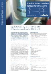
Series (L70, L140 <strong>and</strong> L280) have the same design layout. They only differ by the cold<br />
box diameter. Figure 3 shows a L140 liquefier.<br />
For all L-Series <strong>plants</strong> the same Siemens S7-300 control strategy <strong>and</strong> the same<br />
s<strong>of</strong>tware (PLC) has been designed. In addition a state-<strong>of</strong>-the-art visualisation is available<br />
for the L-Series. The control panel is separated from the cold box, which provides<br />
additional flexibility for the installation <strong>of</strong> the plant. Plant components are operated with a<br />
decentred control system <strong>and</strong> are connected by PROFIBUS DA. Field wiring is minimised<br />
<strong>and</strong> maximum flexibility concerning placement is ensured.<br />
FIGURE 2. TED 16 turbine with cooler FIGURE 3. State <strong>of</strong> the art <strong>helium</strong> liquefier L140
TABLE 1. Performance data <strong>of</strong> L-Series <strong>plants</strong> with <strong>and</strong> without LIN precooling compared to TCF <strong>plants</strong><br />
Compressor with LIN with LIN Performance average P. wo LIN wo LIN Performance average P.<br />
massflow m_liq m_liq increase increase m_liq m_liq increase increase<br />
[g/s] [l/h] [l/h] [%] [%] [l/h] [l/h] [%] [%]<br />
79.5 293 190 54 153 90 70<br />
61.6 226 150 51 52<br />
115 70 64<br />
67<br />
54.2 197 130 52 101 60 68<br />
40.8 140 78 80 70 37 89<br />
34.3 116 57 104 95<br />
59 30 97<br />
91<br />
27.5 91 45 102 46 25 86<br />
21.1 68 39 74 34 23 47<br />
17.7 54 27 102 98<br />
28 15 86<br />
74<br />
14.5 41 19 117 21 11 88<br />
L280<br />
L140<br />
L70<br />
TCF50<br />
TCF20<br />
TCF10<br />
COMPARISON OF PERFORMANCE DATA: L-SERIES VS. TCF<br />
Table 1 shows performance data <strong>of</strong> the L-Series liquefier in comparison to the TCF-<br />
Series. Liquefaction rates <strong>of</strong> TED equipped L-Series <strong>plants</strong> are based on constant<br />
isentropic efficiencies <strong>of</strong> 75% for turbine 1 <strong>and</strong> 80% for turbine 2, according to the<br />
measurements <strong>of</strong> Schoenfeld et al. [1]. The cold box inlet state is 13.0 bar <strong>and</strong> 313K for L-<br />
Series <strong>and</strong> TCF <strong>plants</strong>. Dewar pressure is 1.20 bar (4.4 K) for L-Series <strong>plants</strong> <strong>and</strong> 1.25 bar<br />
(4.45 K) for TCF <strong>plants</strong>. Assumed heat in leak into dewar <strong>and</strong> transfer line are 10 Watt for<br />
both types. Using the same mass flow <strong>and</strong> thus compression power, <strong>liquefaction</strong> capacities<br />
have been increased between 47 <strong>and</strong> 97% for operation without LN2pre-cooling. For<br />
operation with LN2 pre-cooling, the increase <strong>of</strong> <strong>liquefaction</strong> capacity is between 51 <strong>and</strong><br />
117%. In [1], a TCF20 was equipped with TED turbines. The increase <strong>of</strong> the <strong>liquefaction</strong><br />
rate was 52% compared to a TGL-equipped TCF20. The combination <strong>of</strong> TED turbines <strong>and</strong><br />
improved heat exchangers in L140 lead to an increase <strong>of</strong> up to 102% compared to a TCF<br />
with the same compressor mass flow.<br />
Consequently, the specific compression power input per liquefied <strong>helium</strong> could be<br />
significantly reduced.<br />
L280<br />
L140<br />
L70<br />
TCF50<br />
TCF20<br />
TCF10<br />
[ kW l LHe @4.<br />
4K<br />
]<br />
p = PComp<br />
m&<br />
liq<br />
(1)<br />
Pcomp is the shaft power <strong>of</strong> the <strong>helium</strong> recycle compressor. In Table data for L-Series <strong>and</strong><br />
TCF <strong>plants</strong> are presented. The required power for LN2 is not considered for the specific<br />
compression power.<br />
For <strong>liquefaction</strong> <strong>of</strong> one litre liquid <strong>helium</strong> at 4.4 K without LN2, between 1.54 <strong>and</strong><br />
2.22 kW <strong>of</strong> compression power is required for a L-Series plant. For TCF <strong>plants</strong>, between<br />
2.62 <strong>and</strong> 4.06 kW are necessary (Table 2). This means, that for instance a L280 requires a<br />
third less compression input power per produced litre LHe than a TCF50. Table shows p<br />
for <strong>liquefaction</strong> with LN2 pre-cooling as well. L-series <strong>plants</strong> require between 33% <strong>and</strong><br />
50% less specific compression power for operation with LN2 pre-cooling.<br />
Results from the first operating <strong>plants</strong><br />
More than twenty <strong>plants</strong> have been ordered until now <strong>and</strong> several have already been<br />
commissioned. The first four <strong>plants</strong> are already in operation. The L280 at Ibaraki, Japan is<br />
operating with 9.6 bar <strong>and</strong> 313K high pressure inlet state. Liquefaction capacities <strong>of</strong> 220l/h<br />
without purifier operation have been achieved. Cool down time from ambient to operation
TABLE 2. Specific compression power for L-Series <strong>plants</strong> compared to TCF <strong>plants</strong><br />
Compressor with LIN with LIN p_spec av. p_spec wo LIN wo LIN p_spec av. p_spec<br />
massflow p_spec p_spec decrease decrease p_spec p_spec decrease decrease<br />
[g/s] [kW/l Lhe] [kW/l Lhe] [%] [%] [kW/l Lhe] [kW/l Lhe] [%] [%]<br />
79.5 0.81 1.24 35 1.54 2.62 41<br />
61.6 0.90 1.36 34 34<br />
1.78 2.91 39<br />
40<br />
54.2 0.87 1.32 34 1.70 2.85 40<br />
40.8 0.92 1.66 44 1.85 3.50 47<br />
34.3 0.92 1.87 51 49<br />
1.81 3.55 49<br />
47<br />
27.5 0.99 2.01 51 1.95 3.62 46<br />
21.1 1.02 1.77 43 2.04 3.00 32<br />
17.7 1.03 2.08 50 49<br />
2.01 3.75 46<br />
42<br />
14.5 1.11 2.42 54 2.22 4.17 47<br />
L280<br />
L140<br />
L70<br />
TCF50<br />
TCF20<br />
TCF10<br />
temperature is below 2.5 hours. To cool down a similar TCF50, approximately 4 hours<br />
were necessary.<br />
CONCLUSION<br />
By using high efficient TED turbines <strong>and</strong> optimised heat exchangers, <strong>liquefaction</strong><br />
capacities have been increased by 50% to 100% in comparison to the old liquefier<br />
generation. The power input per litre LHe produced has been decreased by 33% to 50%.<br />
The L-Series from Linde Kryotechnik AG established a new benchmark for small scale<br />
<strong>helium</strong> liquefiers <strong>and</strong> refrigerators.<br />
REFERENCES<br />
Schoenfeld H., Cretegny D. <strong>and</strong> Loehlein K., "St<strong>and</strong>ard liquefier-test results with improved turbines", ICEC<br />
– 20, Beijing, China, 2004, pp. 119-122<br />
L280<br />
L140<br />
L70<br />
TCF50<br />
TCF20<br />
TCF10


