Optical Communication Systems (OPT428) - The Institute of Optics ...
Optical Communication Systems (OPT428) - The Institute of Optics ...
Optical Communication Systems (OPT428) - The Institute of Optics ...

Create successful ePaper yourself
Turn your PDF publications into a flip-book with our unique Google optimized e-Paper software.
<strong>Optical</strong> <strong>Communication</strong> <strong>Systems</strong> (<strong>OPT428</strong>)<br />
Govind P. Agrawal<br />
<strong>Institute</strong> <strong>of</strong> <strong>Optics</strong><br />
University <strong>of</strong> Rochester<br />
Rochester, NY 14627<br />
c○2007 G. P. Agrawal<br />
1/549<br />
◭◭<br />
◮◮<br />
◭<br />
◮<br />
Back<br />
Close
Course Outline<br />
• Introduction<br />
• <strong>Optical</strong> Signal Generation<br />
• Signal Propagation in Fibers<br />
• Nonlinear Impairments in Fibers<br />
• Signal Recovery and Bit Error Rate<br />
• Loss Management: <strong>Optical</strong> Amplifiers<br />
• Dispersion Management Techniques<br />
• Nonlinearity Management Techniques<br />
• Multichannel Lightwave <strong>Systems</strong><br />
• <strong>Optical</strong> Networks<br />
2/549<br />
◭◭<br />
◮◮<br />
◭<br />
◮<br />
Back<br />
Close
Historical Perspective<br />
• Smoke signals;
Historical Perspective<br />
Electrical Era<br />
• Telegraph; 1836<br />
• Telephone; 1876<br />
• Coaxial Cables; 1840<br />
• Microwaves; 1948<br />
<strong>Optical</strong> Era<br />
• <strong>Optical</strong> Fibers; 1978<br />
• <strong>Optical</strong> Amplifiers; 1990<br />
• WDM Technology; 1996<br />
• Multiple bands; 2002<br />
• Microwaves and coaxial cables limited to B ∼ 100 Mb/s.<br />
• <strong>Optical</strong> systems can operate at bit rate >10 Tb/s.<br />
• Improvement in system capacity is related to the high frequency <strong>of</strong><br />
optical waves (∼200 THz at 1.5 µm).<br />
4/549<br />
◭◭<br />
◮◮<br />
◭<br />
◮<br />
Back<br />
Close
Information Revolution<br />
• Industrial revolution <strong>of</strong> 19th century gave way to<br />
information revolution during the 1990s.<br />
• Fiber-Optic Revolution is a natural consequence <strong>of</strong> the<br />
Internet growth.<br />
c○2004 TRG, PriMetrica, Inc.<br />
5/549<br />
◭◭<br />
◮◮<br />
◭<br />
◮<br />
Back<br />
Close
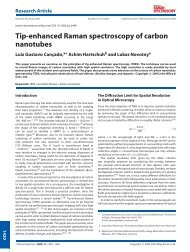
Five Generations<br />
B it R ate (G b/s)<br />
• 0.8-µm systems (1980); Graded-index fibers<br />
• 1.3-µm systems (1985); Single-mode fibers<br />
• 1.55-µm systems (1990); Single-mode lasers<br />
• WDM systems (1996); <strong>Optical</strong> amplifiers<br />
• L and S bands (2001); Raman amplification<br />
10000<br />
1000<br />
100<br />
10<br />
1<br />
0.1<br />
R esearch<br />
C ommercial<br />
0.01<br />
1980 1985 1990 1995 2000 2005<br />
Y ear<br />
6/549<br />
◭◭<br />
◮◮<br />
◭<br />
◮<br />
Back<br />
Close
Lightwave System Components<br />
Generic System<br />
Electrical<br />
Input<br />
<strong>Optical</strong><br />
Transmitter<br />
<strong>Communication</strong> Channel<br />
<strong>Optical</strong><br />
Receiver<br />
Electrical<br />
Output<br />
• <strong>Optical</strong> Transmitters:<br />
Convert electrical data into an optical bit stream suitable for<br />
transmission.<br />
• <strong>Communication</strong> Channel:<br />
<strong>Optical</strong> fibers are used for transmitting optical bit streams in most<br />
terrestrial networks.<br />
• <strong>Optical</strong> Receivers:<br />
Convert optical bit stream into the original electrical form.<br />
7/549<br />
◭◭<br />
◮◮<br />
◭<br />
◮<br />
Back<br />
Close
<strong>Optical</strong> Transmitters<br />
Driving<br />
Circuit<br />
<strong>Optical</strong><br />
Source<br />
Modulator<br />
Electronics<br />
<strong>Optical</strong><br />
Modulator<br />
Electrical<br />
Input<br />
<strong>Optical</strong><br />
Output<br />
• <strong>Optical</strong> source (laser or LED) provides the optical carrier.<br />
• Carrier frequency varies from 185 to 200 THz (1520 to 1620 nm).<br />
• C band: 1530 to 1570 nm; L band: 1570 to 1610 nm.<br />
• Modulator creates the optical bit stream.<br />
• Direct modulation technique: laser current modulated to produce<br />
the bit stream (no external modulator needed).<br />
8/549<br />
◭◭<br />
◮◮<br />
◭<br />
◮<br />
Back<br />
Close
<strong>Optical</strong> Receivers<br />
<strong>Optical</strong><br />
Input<br />
Driving<br />
Circuit<br />
Photodetector<br />
Demodulator<br />
Electronics<br />
Electrical<br />
Demodulator<br />
• Photodetector used for optical-to-electrical conversion.<br />
• Demodulator re-creates the electrical bit stream.<br />
Electrical<br />
Output<br />
• Noise added during transmission and at receiver leads to errors.<br />
• Bit-error rate (BER) is required to be < 10 −9 .<br />
• All receivers need a certain minimum power to operate reliably.<br />
• This power level is known as the receiver sensitivity.<br />
9/549<br />
◭◭<br />
◮◮<br />
◭<br />
◮<br />
Back<br />
Close
Fiber-Optic <strong>Communication</strong> Channel<br />
• Single-mode fibers with low losses (0.2 dB/km near 1550 nm) act<br />
as a communication channel.<br />
• Transmission distance is still limited by fiber losses.<br />
• Losses compensated periodically using regenerators or amplifiers.<br />
• Dispersive and nonlinear effects then limit the total distance.<br />
10/549<br />
◭◭<br />
◮◮<br />
◭<br />
◮<br />
Back<br />
Close
Decibel Units<br />
• Any ratio converted into dB as R (in dB) = 10 log 10 R.<br />
• R = 1 corresponds to 0 dB: Ratios smaller than 1 are negative.<br />
• Signal-to-noise ratio is defined as<br />
SNR = 10 log 10 (PS/PN).<br />
• Loss <strong>of</strong> an optical fiber is expressed in dB units.<br />
• If a 1-mW signal reduces to 1 µW after 100 km <strong>of</strong> fiber, 30-dB loss<br />
translates into a loss <strong>of</strong> 0.3 dB/km.<br />
�<br />
• Power (in dBm) = 10 log10 .<br />
� power<br />
1 mW<br />
• 1 mW corresponds to 0 dBm on the decibel scale.<br />
• 1 µW power corresponds to −30 dBm.<br />
11/549<br />
◭◭<br />
◮◮<br />
◭<br />
◮<br />
Back<br />
Close
Analog and Digital Signals<br />
• Lightwave systems use the digital format.<br />
• <strong>Optical</strong> signal is a stream <strong>of</strong> 0 and 1 bits.<br />
• Bit rate B determines the time slot TB = 1/B for each bit.<br />
12/549<br />
◭◭<br />
◮◮<br />
◭<br />
◮<br />
Back<br />
Close
Advantage <strong>of</strong> Digital Format<br />
1 0 1 (a) 1 0<br />
1<br />
Decison Level<br />
1 0 1 (b) 1 0<br />
1<br />
1 0 1 1 0<br />
1<br />
(c)<br />
• Signal can be recovered in spite <strong>of</strong> noise and distortion.<br />
• If the amplitude exceeds the decision level for a 1 bit, it can be<br />
recovered in spite <strong>of</strong> changes in pulse shape.<br />
• Actual shape <strong>of</strong> the bit is not important.<br />
13/549<br />
◭◭<br />
◮◮<br />
◭<br />
◮<br />
Back<br />
Close
Analog to Digital Conversion<br />
• Sampling:<br />
fs ≥ 2∆ f (sampling theorem).<br />
• Quantization:<br />
M > Amax/AN (error < noise).<br />
• Coding:<br />
M = 2 m ; m bits/sample (Binary<br />
coding).<br />
• Bit rate: B = m fs<br />
B ≥ (2∆ f )log 2 M<br />
B > (∆ f /3)SNR.<br />
SNR = 20 log 10 (Amax/AN).<br />
14/549<br />
◭◭<br />
◮◮<br />
◭<br />
◮<br />
Back<br />
Close
Audio and Video Signals<br />
Digital Audio Signal<br />
• ∆ f = 3.1 kHz (0.3 to 3.4 kHz); SNR = 30 dB.<br />
• Minimum B = (∆ f /3)SNR = 31 kb/s.<br />
• In practice, B = 64 kb/s ( fs = 8 kHz; 8 bits/sample).<br />
Digital Video Signal<br />
• ∆ f = 4 MHz; SNR = 50 dB.<br />
• Minimum B = (∆ f /3)SNR = 66 Mb/s.<br />
• In practice, B = 100 Mb/s ( fs = 10 MHz; 10 bits/sample).<br />
15/549<br />
◭◭<br />
◮◮<br />
◭<br />
◮<br />
Back<br />
Close
Channel Multiplexing<br />
TDM: Time-division multiplexing<br />
FDM: Frequency-division multiplexing<br />
<strong>Optical</strong> FDM = WDM (Wavelength-Division Multiplexing)<br />
16/549<br />
◭◭<br />
◮◮<br />
◭<br />
◮<br />
Back<br />
Close
Time-Division Multiplexing<br />
• No standards until 1988.<br />
• US standard: synchronous optical network (SONET).<br />
• ITU standard: synchronous digital hierarchy (SDH).<br />
SONET SDH B (Mb/s) Channels<br />
OC-1 51.84 672<br />
OC-3 STM-1 155.52 2,016<br />
OC-12 STM-4 622.08 8,064<br />
OC-48 STM-16 2,488.32 32,256<br />
OC-192 STM-64 9,953.28 129,024<br />
OC-768 STM-256 39,813.12 516,096<br />
17/549<br />
◭◭<br />
◮◮<br />
◭<br />
◮<br />
Back<br />
Close
Terrestrial Lightwave <strong>Systems</strong><br />
System Year λ B L Voice<br />
(µm) (Mb/s) (km) Channels<br />
FT–3 1980 0.85 45 < 10 672<br />
FT–3C 1983 0.85 90 < 15 1,344<br />
FT–3X 1984 1.30 180 < 25 2,688<br />
FT–G 1985 1.30 417 < 40 6,048<br />
FT–G-1.7 1987 1.30 1,668 < 46 24,192<br />
STM–16 1991 1.55 2,488 < 85 32,256<br />
STM–64 1996 1.55 9,953 < 90 129,024<br />
STM–256 2002 1.55 39,813 < 90 516,096<br />
• WDM systems commercialized after 1995.<br />
• 160-channel system with 1.6 Tb/s became available by 2000.<br />
18/549<br />
◭◭<br />
◮◮<br />
◭<br />
◮<br />
Back<br />
Close
Wavelength-Division Multiplexing<br />
Tx<br />
Tx<br />
Tx<br />
• Each channel is assigned a unique carrier frequency (ITU grid).<br />
• An optical source at a precise wavelength is employed.<br />
• Channel spacing 50 GHz or less for dense WDM.<br />
19/549<br />
◭◭<br />
◮◮<br />
◭<br />
◮<br />
Back<br />
Close
Undersea Lightwave <strong>Systems</strong><br />
System Year B (Gb/s) L (km) Comments<br />
TAT–8 1988 0.28 70 1.3 µm, multimode lasers<br />
TAT–9 1991 0.56 80 1.55 µm, DFB lasers<br />
TAT–10/11 1993 0.56 80 1.55 µm, DFB lasers<br />
TAT–12/13 1996 5.00 50 1.55 µm, optical amplifiers<br />
AC–1 1998 80.0 50 1.55 µm, WDM, amplifiers<br />
TAT–14 2001 1280 50 1.55 µm, dense WDM<br />
AC–2 2001 1280 50 1.55 µm, dense WDM<br />
360Atlantic 2001 1920 50 1.55 µm, dense WDM<br />
Tycom 2002 2560 50 1.55 µm, dense WDM<br />
FLAG 2002 4800 50 1.55 µm, dense WDM<br />
• By 2001, several WDM systems across the Atlantic Ocean provided<br />
a combined capacity <strong>of</strong> more than 10 Tb/s.<br />
• By 2002, cost <strong>of</strong> calling Europe decreased to
Code-Division Multiplexing<br />
• Borrowed from microwaves (used in cell phones).<br />
• Spectrum <strong>of</strong> each channel spread over a wide range using codes.<br />
• A signature sequence in time domain increases the bandwidth<br />
<strong>of</strong> each channel.<br />
• Channels overlap both in time and frequency domains but<br />
can be decoded using the code.<br />
21/549<br />
◭◭<br />
◮◮<br />
◭<br />
◮<br />
Back<br />
Close
Chapter 2:<br />
<strong>Optical</strong> Signal Generation<br />
• Modulation formats<br />
• Digital data formats<br />
• Bit-stream generation<br />
• Transmitter design<br />
22/549<br />
◭◭<br />
◮◮<br />
◭<br />
◮<br />
Back<br />
Close
Modulation Formats<br />
• <strong>Optical</strong> Carrier:<br />
E(t) = êA0 cos(ω0t − φ0)<br />
• Amplitude-shift keying (ASK): modulate A0<br />
• Frequency-shift keying (FSK): modulate ω0<br />
• Phase-shift keying (PSK): modulate φ0<br />
• Polarization-shift keying (PoSK): information encoded in the polarization<br />
state ê <strong>of</strong> each bit (not practical for optical fibers).<br />
⋆ Most lightwave systems employ ASK.<br />
⋆ ASK is also called on–<strong>of</strong> keying (OOK).<br />
⋆ Differential PSK (DPSK) has been employed in recent years.<br />
23/549<br />
◭◭<br />
◮◮<br />
◭<br />
◮<br />
Back<br />
Close
Modulation Formats<br />
24/549<br />
◭◭<br />
◮◮<br />
◭<br />
◮<br />
Back<br />
Close
ASK Format<br />
• <strong>Optical</strong> field: E(t) = Re[A0(t)exp(iφ0 − iω0t)].<br />
• Only the amplitude A0 is modulated with data.<br />
A0(t) = √ P0∑ n<br />
bn fp(t − nTb).<br />
• Random variable bn = 0 or 1 depending on the bit.<br />
• Direct modulation suffers from the chirping problem.<br />
DFB Laser<br />
CW Input<br />
Modulator<br />
Modulated Output<br />
25/549<br />
◭◭<br />
◮◮<br />
◭<br />
◮<br />
Back<br />
Close
External Modulators<br />
• LiNbO3 modulators are based on the electro-optic effect.<br />
• Refractive index is changed by applying a voltage across it.<br />
• Phase changes converted into amplitude modulation using a<br />
Mach–Zehnder interferometer.<br />
• LiNbO3 modulators can be modulated up to 40 Gb/s.<br />
• Driving voltage can be reduced to 2 to 3 V.<br />
26/549<br />
◭◭<br />
◮◮<br />
◭<br />
◮<br />
Back<br />
Close
Electro-Absorption Modulators<br />
• Insertion losses can be reduced to
PSK Format<br />
• <strong>Optical</strong> field: E(t) = Re[A0 exp(iφ0(t) − iω0t)].<br />
• Only the phase φ0 is modulated with data:<br />
φ0(t) = π ∑ n<br />
bn fp(t − nTb).<br />
• Random variable bn = 0 or 1 depending on the bit.<br />
• <strong>Optical</strong> power remains constant during all bits.<br />
• Information cannot be recovered using just a photodetector.<br />
• Necessary to employ homodyne or heterodyne detection.<br />
28/549<br />
◭◭<br />
◮◮<br />
◭<br />
◮<br />
Back<br />
Close
Heterodyne Detection<br />
• <strong>Optical</strong> bit stream combined coherently with the CW output <strong>of</strong> a<br />
local oscillator (a DFB laser) before the signal is detected.<br />
Ed(t) = A0 exp[iφ0(t) − iω0t] + AL exp(iφL − iωLt).<br />
• Interference between the two optical fields creates a time-dependent<br />
electric current:<br />
Id(t) = Rd(A 2 0 + A 2 L) + 2RdA0AL cos[(ω0 − ωL)t + φ0(t) − φL].<br />
• Rd is the responsivity <strong>of</strong> the photodetector.<br />
• Since Id(t) changes from bit to bit, one can reconstruct the original<br />
bit stream.<br />
29/549<br />
◭◭<br />
◮◮<br />
◭<br />
◮<br />
Back<br />
Close
Phase-Modulated Bit Stream<br />
• Implementation <strong>of</strong> PSK requires an external modulator capable <strong>of</strong><br />
changing optical phase in response to an applied voltage.<br />
• A LiNbO3 modulator can be used for this purpose.<br />
• Design simpler than that <strong>of</strong> an amplitude modulator as a MZ interferometer<br />
is no longer needed.<br />
• Semiconductors can also be used to make phase modulators if they<br />
exhibit the electro-optic effect.<br />
• PSK format rarely used in practice because it requires the phase <strong>of</strong><br />
optical carrier to remain stable.<br />
• This requirement puts a stringent condition on the tolerable line<br />
widths <strong>of</strong> the DFB lasers.<br />
30/549<br />
◭◭<br />
◮◮<br />
◭<br />
◮<br />
Back<br />
Close
DPSK Format<br />
• A variant <strong>of</strong> the PSK format, known as differential PSK or DPSK,<br />
is more practical for lightwave systems.<br />
• Information is coded by using the phase difference between two<br />
neighboring bits.<br />
• Phase difference ∆φ = φk − φk−1 is changed by 0 or π, depending<br />
on whether the kth bit is a 0 or 1.<br />
• DPSK format does not suffer from the phase stability problem.<br />
• Information can be recovered as long as the carrier phase remains<br />
stable over a duration <strong>of</strong> two bits.<br />
• This condition is easily satisfied at bit rates above 1 Gb/s because<br />
line width <strong>of</strong> a DFB laser is typically
QPSK Format<br />
• Another modulation format is known as quaternary PSK (QPSK).<br />
• Phase modulator takes two bits at a time and produces four possible<br />
phases <strong>of</strong> the optical carrier.<br />
• Typically, phase values are 0, π/2, π, and 3π/2 for bit combinations<br />
00, 01, 11, and 10, respectively.<br />
• Such a signal has half the bandwidth compared with the binary PSK<br />
as its bit rate is lower by a factor <strong>of</strong> 2.<br />
• QPSK format suffers from the same phase-stability issue as binary<br />
PSK.<br />
• This problem can be avoided by adopting a differential QPSK<br />
(DQPSK) format.<br />
32/549<br />
◭◭<br />
◮◮<br />
◭<br />
◮<br />
Back<br />
Close
FSK Format<br />
• Information is coded by shifting the carrier frequency ω0 itself.<br />
E(t) = Re[A0 exp[iφ0 − i(ω0 ± ∆ω)t].<br />
• For a binary digital signal, ω0 takes values ω0 − ∆ω and ω0 + ∆ω,<br />
depending on whether a 0 or 1 bit is being transmitted.<br />
• <strong>The</strong> shift 2∆ f is called tone spacing as it represents frequency separation<br />
between 0 and 1 bits.<br />
• FSK format can also be viewed as a special kind <strong>of</strong> PSK modulation<br />
for which the carrier phase increases or decreases linearly.<br />
• Similar to the PSK case, one must employ heterodyne detection for<br />
decoding an FSK-coded optical bit stream.<br />
33/549<br />
◭◭<br />
◮◮<br />
◭<br />
◮<br />
Back<br />
Close
FSK Modulation<br />
• Implementation <strong>of</strong> FSK format requires modulators capable <strong>of</strong> shifting<br />
frequency <strong>of</strong> the incident optical signal.<br />
• Electro-optic materials such as LiNbO3 produce a phase shift proportional<br />
to the applied voltage.<br />
• <strong>The</strong>y can be used for FSK by applying a triangular voltage pulse.<br />
• A linear phase change corresponds to a frequency shift.<br />
• An alternative technique makes use <strong>of</strong> Bragg scattering from acoustic<br />
waves inside an acousto-optic modulator.<br />
• Such modulators can be fabricated by exciting surface acoustic<br />
waves within a LiNbO3 waveguide.<br />
• Simplest method makes use <strong>of</strong> the direct modulation.<br />
34/549<br />
◭◭<br />
◮◮<br />
◭<br />
◮<br />
Back<br />
Close
Digital Data Formats<br />
• Return-to-zero (RZ) format<br />
• nonreturn-to-zero (NRZ) format<br />
35/549<br />
◭◭<br />
◮◮<br />
◭<br />
◮<br />
Back<br />
Close
NRZ Format<br />
• <strong>Optical</strong> pulse occupies the entire bit slot.<br />
• <strong>Optical</strong> power does not drop to zero between successive 1 bits.<br />
• Pulses in an NRZ bit stream do not have the same width.<br />
• Pulse width varies depending on the bit pattern.<br />
• If ten 1 bits occur in succession, a single optical pulse <strong>of</strong> width 10Tb<br />
is used to represent all 10 bits.<br />
• Main advantage: Signal bandwidth is smaller than the RZ format<br />
by about a factor <strong>of</strong> 2.<br />
• This is the reason why the NRZ format is used whenever bandwidth<br />
should be economized as much as possible.<br />
• NRZ format cannot tolerate even a relatively small amount <strong>of</strong> pulse<br />
broadening.<br />
36/549<br />
◭◭<br />
◮◮<br />
◭<br />
◮<br />
Back<br />
Close
RZ Format<br />
• Each optical pulse is shorter than the bit slot.<br />
• All pulses are identical in an RZ bit stream but the spacing among<br />
them depends on the bit pattern.<br />
• How wide the optical pulse should be compared to the bit slot?<br />
• <strong>The</strong> ratio Tp/Tb is referred to as the duty cycle.<br />
• Duty cycle is just a design parameter that can be tailored to help<br />
meet design goals.<br />
• Several variants <strong>of</strong> the RZ format used in practice:<br />
⋆ chirped RZ (CRZ) format<br />
⋆ carrier-suppressed RZ (CSRZ) format.<br />
37/549<br />
◭◭<br />
◮◮<br />
◭<br />
◮<br />
Back<br />
Close
Power Spectral Density<br />
• Electric field: E(t) = Re[A(t)exp(−iω0t)].<br />
• In the case <strong>of</strong> the ASK format<br />
� ∞<br />
bnAp(t − nTb) ≡ b(t ′ )Ap(t −t ′ )dt ′ .<br />
A(t) = ∑ n<br />
• b(t) = ∑n bnδ(t − nTb) is the impulse response <strong>of</strong> an filter.<br />
• Power spectral density is found from the Wiener–Khintchine<br />
theorem: SA(ω) = � ∞<br />
−∞ ΓA(τ)exp(iωτ)dτ.<br />
−∞<br />
• Autocorrelation function ΓA(τ) = 〈A ∗ (t)A(t + τ)〉.<br />
It follows that SA(ω) = |Ãp(ω)| 2 Sb(ω).<br />
• Fourier transform: Ãp(ω) = � ∞<br />
−∞ Ap(t)exp(iωt)dt.<br />
38/549<br />
◭◭<br />
◮◮<br />
◭<br />
◮<br />
Back<br />
Close
Autocorrelation Function<br />
• First calculate the autocorrelation function <strong>of</strong> b(t) using<br />
Γb(τ) = 〈b(t)b(t + τ)〉 = ∑ n<br />
∑ k<br />
〈bnbk〉δ(t − kTb)δ(t + τ − nTb).<br />
• Replace ensemble average with a time average. Using n − k = m<br />
Γb(τ) = 1<br />
Tb ∑ m<br />
• Power spectral density:<br />
rmδ(τ − mTb), rm = lim<br />
N→∞<br />
1<br />
N ∑ n<br />
∞<br />
2 1<br />
SA(ω) = |Ãp(ω)| ∑ rm exp(imωTb).<br />
Tb m=−∞<br />
bnbn+m.<br />
• Correlation coefficients rm calculated noting that bn equals 1 or 0<br />
with equal probabilities: r0 = 1/2 and rm = 1/4 (m �= 0).<br />
39/549<br />
◭◭<br />
◮◮<br />
◭<br />
◮<br />
Back<br />
Close
Power Spectral Density<br />
• Final expression for power spectral density:<br />
�<br />
SA(ω) =<br />
|Ãp(ω)| 2<br />
4Tb<br />
• Next use the well-known identity<br />
1 +<br />
∞<br />
∑ exp(inωTb) =<br />
n=−∞<br />
2π<br />
Tb<br />
∞<br />
∑<br />
m=−∞<br />
exp(imωTb)<br />
�<br />
∞ �<br />
∑ δ ω −<br />
n=−∞<br />
2πn<br />
�<br />
.<br />
Tb<br />
• Power spectral density <strong>of</strong> A(t) then becomes<br />
�<br />
2 |Ãp(ω)|<br />
SA(ω) = 1 +<br />
4Tb<br />
2π<br />
�<br />
ω −<br />
Tb<br />
2πm<br />
�<br />
Tb<br />
�<br />
.<br />
∞<br />
∑ δ<br />
m=−∞<br />
• <strong>The</strong> spectrum consists <strong>of</strong> a continuous part and a discrete part<br />
resulting from the sum over delta functions.<br />
.<br />
40/549<br />
◭◭<br />
◮◮<br />
◭<br />
◮<br />
Back<br />
Close
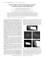
Spectral Density <strong>of</strong> NRZ Bit Stream<br />
• Assuming a rectangular shape, Ap(t) = √ P0 within the bit slot <strong>of</strong><br />
duration Tb and 0 outside <strong>of</strong> it.<br />
• Pulse spectrum: |Ãp(ω)| 2 = P0T 2<br />
b sinc2 (ωTb/2).<br />
• Spectral density <strong>of</strong> the entire bit stream:<br />
SA(ω) = P0Tb<br />
4 sinc2 (ωTb/2) + π<br />
2 P0.<br />
• Only the m = 0 term survives in the sum.<br />
• <strong>The</strong> sinc function vanishes at all frequencies such that ω = 2πm/Tb<br />
except when m = 0.<br />
41/549<br />
◭◭<br />
◮◮<br />
◭<br />
◮<br />
Back<br />
Close
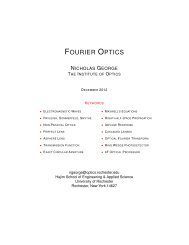
Spectral Density <strong>of</strong> RZ Bit Stream<br />
• Spectral density <strong>of</strong> an RZ bit stream depends on the duty cycle.<br />
• Each 1 bit occupies a fraction dc <strong>of</strong> the bit slot.<br />
• Assuming a rectangular shape for the optical pulse<br />
|Ãp(ω)| 2 = P0T 2<br />
b dc sinc 2 (ωTbdc/2).<br />
• Spectrum wider for RZ pulses and contains discrete spectral components.<br />
Spectral Density<br />
1.0<br />
0.8<br />
0.6<br />
0.4<br />
0.2<br />
0<br />
4<br />
(a)<br />
3<br />
2<br />
1<br />
0<br />
−1<br />
NRZ<br />
−2<br />
Normalized Frequency<br />
−3<br />
−4<br />
Spectral Density<br />
1.0<br />
0.8<br />
0.6<br />
0.4<br />
0.2<br />
(b)<br />
RZ<br />
0<br />
−4 −3 −2 −1 0 1 2 3 4<br />
Normalized Frequency<br />
42/549<br />
◭◭<br />
◮◮<br />
◭<br />
◮<br />
Back<br />
Close
Bit-Stream Generation<br />
• NRZ Transmitters: Design relatively simple if the electrical signal<br />
is itself in the NRZ format.<br />
• A Mach–Zehnder modulator converts the CW light into an optical<br />
bit stream.<br />
CW Input<br />
Contacts<br />
MZI<br />
NRZ Output<br />
• Modulator can be integrated with the DFB laser if the electroabsorption<br />
effect is used for modulation.<br />
43/549<br />
◭◭<br />
◮◮<br />
◭<br />
◮<br />
Back<br />
Close
Transmission <strong>of</strong> a MZ modulator<br />
• Outputs Ab and Ac from the bar and cross ports:<br />
� �<br />
Ab<br />
��<br />
iφ e 1 0<br />
Ac<br />
= 1<br />
2<br />
� 1 i<br />
i 1<br />
0 e iφ 2<br />
�� 1 i<br />
i 1<br />
�� Ai<br />
0<br />
• φ j(t) = πVj(t)/Vπ is the phase shift when voltage Vj is applied.<br />
• Transmission: tm = Ab/Ai = cos[(φ1−φ2)/2] exp[i(φ1+φ2+π)/2].<br />
• φ1 + φ2 constant if V2(t) = −V1(t) +Vb:<br />
Tm(t) = |tm| 2 = cos 2<br />
� �<br />
π<br />
[2V1(t) −Vb] .<br />
2Vπ<br />
• To generate NRZ bit stream, modulator is biased with Vb = −Vπ/2.<br />
• V1(t) varies from −Vπ/4 to +Vπ/4 between 0 and 1 bits.<br />
�<br />
.<br />
44/549<br />
◭◭<br />
◮◮<br />
◭<br />
◮<br />
Back<br />
Close
RZ Transmitters<br />
• Situation different when electrical signal is in the NRZ format.<br />
• One possibility: Use a mode-locked laser.<br />
• Such a laser produces a periodic train <strong>of</strong> pulses <strong>of</strong> appropriate width<br />
at a repetition rate equal to the bit rate B.<br />
• In essence, laser produces an “11111···” bit stream.<br />
• Modulator is then operated such that it blocks the pulse in all slots<br />
representing 0 bits.<br />
• Rarely used for commercial lightwave systems because<br />
mode-locked lasers are not as reliable as a CW semiconductor laser.<br />
45/549<br />
◭◭<br />
◮◮<br />
◭<br />
◮<br />
Back<br />
Close
RZ Transmitters<br />
DFB Laser<br />
NRZ Data Clock<br />
CW NRZ<br />
RZ<br />
Data<br />
Modulator<br />
NRZ-to-RZ<br />
Converter<br />
• An alternative approach makes use <strong>of</strong> the scheme shown above.<br />
• NRZ signal generated first using a data modulator.<br />
• It is converted into an RZ bit stream with a second modulator that<br />
is driven by a sinusoidal signal at the bit rate.<br />
• Second modulator is called the pulse carver.<br />
46/549<br />
◭◭<br />
◮◮<br />
◭<br />
◮<br />
Back<br />
Close
Biasing <strong>of</strong> Modulators<br />
• Three different biasing configurations can be used to create RZ bit<br />
streams with duty cycles ranging from 33 to 67%.<br />
• In one configuration, Vb = Vπ/2 and V1(t) = (Vπ/4)cos(2πBt).<br />
• Since phase shift equals π/2 once during each cycle, each long pulse<br />
representing a string <strong>of</strong> 1’s is split into multiple pulses.<br />
• Such a device acts as an NRZ-to-RZ converter for the optical bit<br />
stream by forcing the output to reduce to zero at the boundaries <strong>of</strong><br />
each bit.<br />
• Transmissivity <strong>of</strong> the second modulator:<br />
Tm(t) = cos 2 [ 1<br />
2 π sin2 (πBt)].<br />
47/549<br />
◭◭<br />
◮◮<br />
◭<br />
◮<br />
Back<br />
Close
RZ bit Stream<br />
Transmissivity<br />
V/V π<br />
1<br />
0.8<br />
0.6<br />
0.4<br />
0.2<br />
0<br />
0 5 10 15 20 25 30 35 40 45 50<br />
2<br />
1.8<br />
1.6<br />
1.4<br />
1.2<br />
(a)<br />
(b)<br />
Time (ps)<br />
1<br />
0 5 10 15 20 25 30 35 40 45 50<br />
Time (ps)<br />
• Duty cycle <strong>of</strong> RZ pulses is about 50%.<br />
• It can be adjusted by reducing the voltage swing and adjusting the<br />
bias voltage applied to the modulator.<br />
48/549<br />
◭◭<br />
◮◮<br />
◭<br />
◮<br />
Back<br />
Close
Biasing <strong>of</strong> Modulators<br />
• In the second configuration, bias voltage Vb = 2Vπ (point <strong>of</strong> maximum<br />
transmission), and V1(t) is modulated at a frequency equal<br />
to B/2 with the peak value Vπ/2.<br />
• Resulting RZ pulses are shorter with a duty cycle <strong>of</strong> 33%.<br />
• In the third configuration, the bias voltage Vb = Vπ (point <strong>of</strong> minimum<br />
transmission), and V1(t) is modulated in periodic fashion at<br />
a frequency equal to B/2.<br />
• This configuration provides a duty cycle <strong>of</strong> 67%.<br />
• Main drawback: Synchronization required between two RF signals<br />
applied to two modulators.<br />
49/549<br />
◭◭<br />
◮◮<br />
◭<br />
◮<br />
Back<br />
Close
Modified RZ Transmitters<br />
• Bandwidth <strong>of</strong> RZ bit stream is larger that <strong>of</strong> the NRZ format.<br />
• Enhancement factor depends on the duty cycle.<br />
• Bandwidth is nearly doubled for a 50% duty cycle.<br />
• This increase forces one to increase wavelength spacing between<br />
two neighboring WDM channels (lower spectral efficiency).<br />
• Spectral efficiency can be improved with suitable modifications.<br />
• One approach: Modulate phase in addition to amplitude.<br />
• Chirped RZ (CRZ format): optical pulses representing 1 bits are<br />
chirped before they are launched into the fiber.<br />
50/549<br />
◭◭<br />
◮◮<br />
◭<br />
◮<br />
Back<br />
Close
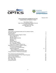
CSRZ Format<br />
• CSRZ stands for carrier-suppressed RZ.<br />
• Phase modulation is used to introduce a π phase shift between any<br />
two neighboring bits.<br />
• This phase alternation modifies signal spectrum such that the central<br />
peak located at the carrier frequency is suppressed.<br />
• CSRZ produces a narrower spectrum than that <strong>of</strong> RZ signal.<br />
• Several other RZ-type formats are possible.<br />
• Figure 2.9 shows experimentally recorded optical spectra at<br />
42.7 Gb/s for several different formats.<br />
• Bit rate is larger than 40 Gb/s because <strong>of</strong> 7% FEC overhead.<br />
• FEC stands for forward error correction.<br />
51/549<br />
◭◭<br />
◮◮<br />
◭<br />
◮<br />
Back<br />
Close
Comparison <strong>of</strong> Signal Spectra<br />
52/549<br />
◭◭<br />
◮◮<br />
◭<br />
◮<br />
Back<br />
Close
CSRZ: A Ternary Format<br />
• A π phase shift for alternate bits is equivalent to changing the sign<br />
<strong>of</strong> the pulse amplitude:<br />
A(t) = ∑ n<br />
(−1) n bnAp(t − nTb) ≡ ∑ n<br />
¯bnAp(t − nTb).<br />
• We can absorb (−1) n in the definition <strong>of</strong> ¯b that is allowed to take<br />
three values (−1, 0, and 1) for each bit.<br />
• CSRZ scheme can be implemented with the same two-modulator<br />
configuration used for the RZ format.<br />
• Second modulator (pulse carver) is operated at half the bit rate<br />
with twice the peak voltage (V1 = Vπ/2).<br />
• Modulator is biased at the point <strong>of</strong> minimum transmission (Vb = Vπ)<br />
and produces pulses with 67% duty cycle.<br />
53/549<br />
◭◭<br />
◮◮<br />
◭<br />
◮<br />
Back<br />
Close
CSRZ Format<br />
Amplitude<br />
V/V π<br />
1<br />
0.5<br />
0<br />
−0.5<br />
−1<br />
2<br />
1.5<br />
1<br />
0.5<br />
0 5 10 15 20 25 30 35 40 45 50<br />
Time (ps)<br />
0<br />
0 5 10 15 20 25 30 35 40 45 50<br />
Time (ps)<br />
• During a single clock cycle, two optical pulses with a relative phase<br />
shift <strong>of</strong> π are created.<br />
(a)<br />
(b)<br />
54/549<br />
◭◭<br />
◮◮<br />
◭<br />
◮<br />
Back<br />
Close
RZ-AMI Format<br />
• A variant <strong>of</strong> CSRZ is format known as the alternate-mark-inversion.<br />
• Spectrum for the RZ-AMI format is quite different.<br />
• A π phase shift is introduced only for 1’s so that alternate 1 bits<br />
have their amplitudes inverted.<br />
• Power spectral density is given by<br />
SA(ω) = 1<br />
|Ãp(ω)|<br />
2Tb<br />
2 [(1 − cos(ωTb)].<br />
• For a 50% duty cycle, SA(ω) = P 0T b<br />
4 sinc2 (ωTb/4)sin 2 (ωTb/2).<br />
• No power at the carrier frequency [SA(ω = 0) = 0].<br />
55/549<br />
◭◭<br />
◮◮<br />
◭<br />
◮<br />
Back<br />
Close
RZ-Duobinary Format<br />
• This format is a variant <strong>of</strong> the RZ-AMI format.<br />
• Phase is changed only when an odd number <strong>of</strong> 0 bits occur between<br />
two successive 1 bits.<br />
• Its use reduces intersymbol interference, a phenomenon that leads<br />
to errors at the receiver.<br />
• This format requires considerable electronic processing <strong>of</strong> the NRZ<br />
data at the transmitter.<br />
• <strong>Optical</strong> spectrum <strong>of</strong> the RZ-duobinary format is similar to that <strong>of</strong><br />
the RZ-AMI format.<br />
56/549<br />
◭◭<br />
◮◮<br />
◭<br />
◮<br />
Back<br />
Close
AP-RZ Format<br />
• A variant <strong>of</strong> the RZ format is known as alternate-phase RZ.<br />
• Phase <strong>of</strong> two neighboring bits is alternated between two values that<br />
differ by a value other than π.<br />
• Phase alternation by π/2 is <strong>of</strong>ten used in practice.<br />
• Spectrum for the AP-RZ format is quite different from that <strong>of</strong> the<br />
CSRZ format.<br />
• It contains more spectral peaks because peaks are separated by only<br />
B/2, rather than B.<br />
• Experimental results show that the AP-RZ format can provide a<br />
better system performance compared with other formats.<br />
57/549<br />
◭◭<br />
◮◮<br />
◭<br />
◮<br />
Back<br />
Close
Single-Sideband Format<br />
• Signal bandwidth <strong>of</strong> any modulation format can be reduced by 50%<br />
by adopting a single-sideband scheme.<br />
• Only one sideband, located on either side <strong>of</strong> the carrier frequency,<br />
is transmitted.<br />
• This is possible because the signal spectrum is symmetric around<br />
the carrier frequency.<br />
• Both the upper and lower sidebands contain the entire information<br />
content <strong>of</strong> the signal.<br />
• Generation <strong>of</strong> an optical bit stream with a single sideband is not a<br />
simple task.<br />
58/549<br />
◭◭<br />
◮◮<br />
◭<br />
◮<br />
Back<br />
Close
Single-Modulator Schemes<br />
• Double-modulator configuration used for the RZ format suffers from<br />
a synchronization problem.<br />
• It turns out that an RZ pulse train can be generated using a single<br />
modulator driven by a differentially encoded NRZ signal.<br />
• Voltage level changes between its two values whenever next bit is a<br />
“1” bit.<br />
• Modulator is biased at the peak <strong>of</strong> its transmission (Vb = Vπ).<br />
Tm(V1) = sin 2<br />
� �<br />
π<br />
[2V1(t) −Vπ] = cos<br />
2Vπ<br />
2 [πV1(t)/Vπ].<br />
• An optical pulse is produced whenever electrical signal changes from<br />
low to high or high to low.<br />
59/549<br />
◭◭<br />
◮◮<br />
◭<br />
◮<br />
Back<br />
Close
Single-Modulator Schemes<br />
• Another scheme in which a single phase modulator produces an RZ<br />
signal from a differentially encoded NRZ bit stream.<br />
• A π phase shift is produced whenever the voltage is nonzero.<br />
• Phase-encoded optical signal is split into two equal parts inside a<br />
MZ interferometer.<br />
• It is delayed in one branch by a fraction <strong>of</strong> bit slot.<br />
60/549<br />
◭◭<br />
◮◮<br />
◭<br />
◮<br />
Back<br />
Close
Single-Modulator Schemes<br />
NRZ data<br />
Phase changes by π for every 1 bit (RZ-AMI format).<br />
Differential encoding<br />
Phase pr<strong>of</strong>iles in two arms<br />
Final RZ bit stream<br />
Phase variation across it<br />
61/549<br />
◭◭<br />
◮◮<br />
◭<br />
◮<br />
Back<br />
Close
DPSK Transmitters<br />
• Two modulators used at the transmitter end; second modulator acts<br />
as a pulse carver.<br />
• A Mach–Zehnder interferometer employed at receiver to convert<br />
phase information into current variations.<br />
62/549<br />
◭◭<br />
◮◮<br />
◭<br />
◮<br />
Back<br />
Close
DPSK Receivers<br />
• Length difference between two arms <strong>of</strong> the MZ interferometer is<br />
corresponds to a delay <strong>of</strong> exactly one bit slot.<br />
• One-bit delay allows us to reconstruct the original bit stream using<br />
a direct-detection scheme.<br />
• MZ interferometer acts as an optical filter as follows:<br />
� �<br />
Ãb<br />
= 1<br />
� �� �� ��<br />
iωT 1 i e b 0 1 i Ã(ω)<br />
2 i 1 0 1 i 1 0<br />
Ãc<br />
• After Fourier transforming, power falling at the photodetector<br />
P(t) = 1<br />
4 |A(t) ± A(t − Tb)| 2 .<br />
• Choice <strong>of</strong> sign depends on whether the bar or cross port is used.<br />
• Current at the receiver Id(t) = RdP(t) 1<br />
2 [1 ± cos(∆φ)],<br />
where ∆φ(t) = φ(t) − φ(t − Tb).<br />
�<br />
.<br />
63/549<br />
◭◭<br />
◮◮<br />
◭<br />
◮<br />
Back<br />
Close
Transmitter Design<br />
• Design <strong>of</strong> optical transmitters requires attention to many details.<br />
• Applications related to computer-data and access networks have low<br />
cost as a major design objective.<br />
• <strong>The</strong>y employ low-power transmitters based on LEDs or VCSELs<br />
and do not require internal cooling.<br />
• For metropolitan networks, low cost remains important but bit rates<br />
are higher (typically 2.5 Gb/s).<br />
• Such networks use directly modulated semiconductor lasers.<br />
• Submarine and terrestrial long-haul systems operate at high speeds<br />
and employ multiple WDM channels.<br />
• Design requirements are most stringent for such systems.<br />
64/549<br />
◭◭<br />
◮◮<br />
◭<br />
◮<br />
Back<br />
Close
DFB-Laser Transmitters<br />
• A distributed feedback (DFB) semiconductor laser is invariably used<br />
for stabilizing the channel wavelength.<br />
• CW light from the DFB laser is coupled to a modulator as<br />
efficiently as possible.<br />
• Modulator is <strong>of</strong>ten integrated with the laser.<br />
• If that is not possible, an external LiNbO3 modulator is employed.<br />
• In both cases, optical bit stream generated needs to be launched<br />
into the fiber link without significant coupling losses.<br />
• It is important to avoid and feedback into the transmitter.<br />
• <strong>The</strong> output power needs to remain constant with aging.<br />
• Several transmitter designs developed to meet these requirements.<br />
65/549<br />
◭◭<br />
◮◮<br />
◭<br />
◮<br />
Back<br />
Close
Coupling Losses and Output Stability<br />
• Coupling efficiency depends on optical source (LED versus laser) as<br />
well as on fiber (multimode versus single mode).<br />
• Coupling inefficient when light from an LED is coupled into a singlemode<br />
fiber.<br />
• Coupling efficiency for semiconductor lasers is 40 to 50% and can<br />
exceed 80% for VCSELs because <strong>of</strong> their circular spot size.<br />
• A small piece <strong>of</strong> fiber (known as the pigtail) is included with every<br />
transmitter; coupling efficiency is maximized during packaging.<br />
• A fiber connector is used to join the pigtail with the fiber cable.<br />
• Two approaches are used for coupling light into fiber.<br />
66/549<br />
◭◭<br />
◮◮<br />
◭<br />
◮<br />
Back<br />
Close
DFB-Laser Transmitters<br />
67/549<br />
◭◭<br />
◮◮<br />
◭<br />
◮<br />
Back<br />
Close
Butt Coupling Issues<br />
• Butt coupling provides only 10–20% efficiency if mode sizes<br />
are not matched.<br />
• Typically, semiconductor lasers have an elliptical spot size <strong>of</strong> size 1<br />
to 2 µm.<br />
• Mode diameter <strong>of</strong> single-mode fibers exceeds 8 µm.<br />
• Coupling efficiency can be improved by tapering the fiber.<br />
• Fiber tip is aligned with the emitting region <strong>of</strong> the laser to maximize<br />
the coupling efficiency (typically 40%).<br />
• Use <strong>of</strong> a lensed fiber can provide values close to 80% .<br />
68/549<br />
◭◭<br />
◮◮<br />
◭<br />
◮<br />
Back<br />
Close
Lens Coupling Issues<br />
• A sphere-shape lens is used to collimate laser light and focus it onto<br />
the fiber core.<br />
• Coupling efficiency exceeds 70% for a confocal design.<br />
• Alignment <strong>of</strong> the fiber core is less critical for the confocal design<br />
because spot size is magnified to match fiber’s mode size.<br />
• Mechanical stability <strong>of</strong> the package is ensured by soldering the fiber<br />
into a ferrule.<br />
• Ferrule secured to the body by two sets <strong>of</strong> laser alignment welds.<br />
• One set <strong>of</strong> welds establishes proper axial alignment, while the other<br />
set provides transverse alignment.<br />
• A spot-size converter is sometimes used for maximizing the<br />
coupling efficiency (>80% possible).<br />
69/549<br />
◭◭<br />
◮◮<br />
◭<br />
◮<br />
Back<br />
Close
<strong>Optical</strong> Feedback Issues<br />
• Semiconductor lasers are sensitive to optical feedback.<br />
• Even a small amount <strong>of</strong> feedback (
Output Power Stability<br />
• Each system is designed to operate with a certain amount <strong>of</strong> power.<br />
• This power should be maintained during system lifetime.<br />
• In practice, power level can change if coupling losses change because<br />
<strong>of</strong> mechanical motion <strong>of</strong> transmitter components.<br />
• It can also change if the threshold current <strong>of</strong> laser itself increases<br />
because <strong>of</strong> aging-related degradations.<br />
• To keep the power constant, most transmitters incorporate a mechanism<br />
that adjusts the current in a dynamic fashion.<br />
• This is realized by a monitoring photodiode, which generates a control<br />
signal that is used to adjust the bias level.<br />
• Rear facet <strong>of</strong> the laser is generally used for this purpose.<br />
71/549<br />
◭◭<br />
◮◮<br />
◭<br />
◮<br />
Back<br />
Close
Wavelength Stability and Tunability<br />
• Dense WDM systems operate with a channel spacing as small as<br />
25 GHz (or 0.2 nm).<br />
• Wavelength <strong>of</strong> each optical carrier should remains stable to within<br />
1 GHz or so (within 10 pm).<br />
• Use <strong>of</strong> DFB lasers helps because wavelength is set by a built-in<br />
grating internal to the laser structure.<br />
• Wavelength is set by the grating period Λ through<br />
the Bragg condition λB = 2 ¯nΛ.<br />
• Stability <strong>of</strong> λB requires the mode index ¯n to remain constant during<br />
system operation.<br />
72/549<br />
◭◭<br />
◮◮<br />
◭<br />
◮<br />
Back<br />
Close
Wavelength Stability<br />
• Near 1550 nm, wavelength can remain stable to within 10 pm<br />
only if changes in ¯n are below 10 −5 .<br />
• Temperature variation <strong>of</strong> even 1 ◦ C can change ¯n<br />
by an amount > 10 −5 .<br />
• one must control laser temperature to a fraction <strong>of</strong> 1 ◦ C.<br />
• This is realized in practice by a thermoelectric cooler<br />
within the transmitter.<br />
• Advanced transmitters employ a wavelength-monitoring scheme and<br />
control laser wavelength using a servo-loop mechanism.<br />
• Several different schemes have been employed for this purpose.<br />
73/549<br />
◭◭<br />
◮◮<br />
◭<br />
◮<br />
Back<br />
Close
Wavelength Monitoring<br />
• Light from the back facet <strong>of</strong> the DFB laser is split into two branches<br />
using a prism.<br />
• A Fabry–Perot étalon serves as a wavelength reference.<br />
• It is designed such that one <strong>of</strong> its transmission peaks occurs precisely<br />
at the wavelength at which the laser is designed to operate.<br />
74/549<br />
◭◭<br />
◮◮<br />
◭<br />
◮<br />
Back<br />
Close
Wavelength Monitoring<br />
• Fabry–Perot étalon suffers from one problem.<br />
• Variations in étalon temperature can affect its cavity length<br />
and its refractive index and shift its transmission peaks in an<br />
uncontrolled manner.<br />
• A feedback loop solves this problem by monitoring étalon temperature<br />
and adjusting the feedback signal accordingly.<br />
• Laser wavelength is kept constant by adjusting thermoelectric cooler<br />
current and changing laser temperature.<br />
• With this approach, laser wavelength drifted by less than 1 pm even<br />
when laser module temperature varied from 5 to 70 ◦ C.<br />
• Reliability tests indicate that wavelength drift should be less than<br />
5 pm during a 25-year operating period.<br />
75/549<br />
◭◭<br />
◮◮<br />
◭<br />
◮<br />
Back<br />
Close
Wavelength Tuning<br />
• A large number <strong>of</strong> DFB lasers, each operating at a fixed wavelength<br />
on the ITU grid, is required for dense WDM systems.<br />
• Maintenance <strong>of</strong> WDM transmitter with 100 or more channels is impractical<br />
because one must maintain a large inventory <strong>of</strong> individual<br />
DFB lasers.<br />
• A solution is provided by tunable lasers whose wavelength can be<br />
tuned over a wide range electronically.<br />
• Multisection DFB and distributed Bragg reflector (DBR) lasers have<br />
been developed to meet the conflicting requirements <strong>of</strong> stability and<br />
tunability.<br />
76/549<br />
◭◭<br />
◮◮<br />
◭<br />
◮<br />
Back<br />
Close
Multisection Lasers<br />
• A tunable DBR laser consists <strong>of</strong> active, phase-control, and Bragg<br />
sections. Each section can be biased independently.<br />
• Current injected into the Bragg section changes Bragg wavelength<br />
through carrier-induced changes in the refractive index ¯n.<br />
• Current injected into the phase-control section changes the phase<br />
<strong>of</strong> feedback through index changes in that section.<br />
• Laser wavelength can be tuned almost continuously over the 10 to<br />
15 nm by controlling currents in these sections.<br />
• By 1998, such lasers exhibited a tuning range <strong>of</strong> 17 nm and output<br />
powers <strong>of</strong> up to 100 mW.<br />
• Several new designs have been developed for tunable lasers.<br />
77/549<br />
◭◭<br />
◮◮<br />
◭<br />
◮<br />
Back<br />
Close
Sampled-grating DBR Lasers<br />
• Sampled-grating DBR (SG-DBR) laser consists <strong>of</strong> four sections.<br />
• Each section be controlled electronically by injecting currents.<br />
• Two outer sections act as DBRs and are designed with a<br />
superstructure grating.<br />
• Such lasers can be tuned over 100 nm with Vernier effect.<br />
• Each SG-DBR section supports its own comb <strong>of</strong> wavelengths but<br />
spacing in each comb is not the same.<br />
• <strong>The</strong> wavelength coinciding in the two combs becomes the output<br />
wavelength that can be tuned over a wide range.<br />
78/549<br />
◭◭<br />
◮◮<br />
◭<br />
◮<br />
Back<br />
Close
Multisection Lasers<br />
• In another design, a grating-assisted directional coupler is inserted<br />
between the active and phase-control sections.<br />
• Coupler section has two vertically separated waveguides so that they<br />
form an asymmetric directional coupler.<br />
• Grating can selectively transfer a single wavelength from the wavelength<br />
comb supported by the DBR section.<br />
• Such lasers can provide a tuning range <strong>of</strong> more than 110 nm.<br />
79/549<br />
◭◭<br />
◮◮<br />
◭<br />
◮<br />
Back<br />
Close
Monolithic Integration<br />
• Performance <strong>of</strong> high-speed transmitters can be improved by<br />
integrating monolithically the laser with driver electronics.<br />
• Such monolithic transmitters are referred to as optoelectronic integrated<br />
circuits (OEICs).<br />
• By 1995, 10-Gb/s laser transmitters were fabricated by integrating<br />
1.55-µm DFB lasers with field-effect transistors.<br />
• Concept <strong>of</strong> monolithic integration can be extended to build singlechip<br />
transmitters by adding more functionality on the same chip.<br />
• Such devices are called photonic integrated circuits, as they integrate<br />
on the same chip multiple optical components.<br />
80/549<br />
◭◭<br />
◮◮<br />
◭<br />
◮<br />
Back<br />
Close
Monolithic Integration <strong>of</strong> Modulator<br />
• Performance can be improved by integrating an electro-absorption<br />
modulator with the DFB or DBR laser.<br />
• By 2001, modulator-integrated transmitters were able to operate at<br />
a bit rate <strong>of</strong> 40 Gb/s.<br />
• SG-DBR laser can be integrated with a modulator and a semiconductor<br />
optical amplifier (SOA), resulting in a six-section device.<br />
• Use <strong>of</strong> a built-in optical amplifier permits power levels high enough<br />
that more than 10 mW <strong>of</strong> optical power can be coupled to a fiber.<br />
81/549<br />
◭◭<br />
◮◮<br />
◭<br />
◮<br />
Back<br />
Close
Monolithic Integration <strong>of</strong> Modulator<br />
• Even a MZ modulator can be integrated with the laser if InP is used<br />
to make it.<br />
• Device also incorporates a back-facet detector and a SOA.<br />
• Whole device is only 3.4 mm long.<br />
82/549<br />
◭◭<br />
◮◮<br />
◭<br />
◮<br />
Back<br />
Close
Wavelength-Selective Lasers (WSL)<br />
• Multiple DFB lasers on the same chip provide an alternative solution<br />
to tunability.<br />
• Package combines a WSL unit with a wavelength-locking unit that<br />
locks the laser wavelength using a Fabry–Perot étalon.<br />
83/549<br />
◭◭<br />
◮◮<br />
◭<br />
◮<br />
Back<br />
Close
Wavelength-Selective Lasers (WSL)<br />
• <strong>The</strong> WSL unit incorporates an array <strong>of</strong> eight DFB lasers whose<br />
output is sent to a single SOA through an MMI coupler.<br />
• Each DFB laser can be tuned over a few nanometers by changing<br />
its temperature.<br />
• This fine tuning permits setting <strong>of</strong> the transmitter wavelength precisely<br />
on the ITU grid.<br />
• Wavelength can be changed by a much larger value by turning on<br />
individual DFB lasers selectively within the array.<br />
• <strong>The</strong> combination <strong>of</strong> temperature tuning and multi-wavelength arrays<br />
produces transmitters that can operate anywhere within the S,<br />
C, and L bands.<br />
• Entire transmitter can be fitted inside a standard butterfly package.<br />
84/549<br />
◭◭<br />
◮◮<br />
◭<br />
◮<br />
Back<br />
Close
Reliability and Packaging<br />
• <strong>Optical</strong> transmitter should operate reliably over >10 years.<br />
• Reliability requirements are more stringent for submarine systems.<br />
• Since repairs are prohibitively expensive for them, all components<br />
are designed to last at least 25 years.<br />
• Major reason for failure <strong>of</strong> transmitters is the optical source itself.<br />
• Considerable testing performed to ensure a reasonable lifetime.<br />
• It is common to quantify the lifetime by a parameter tF known as<br />
mean time to failure.<br />
• Typically, tF should exceed 10 5 hours (about 11 years).<br />
85/549<br />
◭◭<br />
◮◮<br />
◭<br />
◮<br />
Back<br />
Close
Reliability and Packaging<br />
• Both LEDs and semiconductor lasers can stop operating suddenly<br />
(catastrophic degradation).<br />
• <strong>The</strong>y also exhibit a gradual mode <strong>of</strong> degradation in which device<br />
efficiency degrades with aging.<br />
• Physically, gradual degradation is due to the onset <strong>of</strong> dark-line or<br />
dark-spot defects within the active region <strong>of</strong> the laser.<br />
• Attempts are made to identify devices that are likely to fail.<br />
• A common method is to operate the device at high temperatures<br />
and high current levels (accelerated aging).<br />
• Changes in the operating current at a constant power provide a<br />
measure <strong>of</strong> device degradation.<br />
86/549<br />
◭◭<br />
◮◮<br />
◭<br />
◮<br />
Back<br />
Close
Transmitter Lifetime<br />
• Degradation rate can be used to estimate the laser lifetime and the<br />
mean time to failure (MTTF).<br />
• LEDs are normally more reliable than semiconductor lasers under<br />
the same operating conditions.<br />
• MTTF for GaAs LEDs easily exceeds 10 6 hours and can be >10 7<br />
hours at 25 ◦ C.<br />
• MTTF for InGaAsP LEDs is even larger, approaching a value ∼10 9<br />
hours.<br />
• By contrast, the MTTF for InGaAsP lasers is generally limited to<br />
10 6 hours at 25 ◦ C.<br />
• This value is large enough that semiconductor lasers can be used in<br />
undersea optical transmitters.<br />
87/549<br />
◭◭<br />
◮◮<br />
◭<br />
◮<br />
Back<br />
Close
![Phase retrieval algorithms: a personal tour [Invited] - The Institute of ...](https://img.yumpu.com/25023725/1/190x249/phase-retrieval-algorithms-a-personal-tour-invited-the-institute-of-.jpg?quality=85)