Uprating Through Condenser Reconstruction - Balcke-Dürr ...
Uprating Through Condenser Reconstruction - Balcke-Dürr ...
Uprating Through Condenser Reconstruction - Balcke-Dürr ...

Create successful ePaper yourself
Turn your PDF publications into a flip-book with our unique Google optimized e-Paper software.
Special publication<br />
a 98e<br />
<strong>Uprating</strong> <strong>Through</strong><br />
<strong>Condenser</strong> <strong>Reconstruction</strong><br />
J. Scheurlen, R. Scharf, W. Schulz<br />
VGB Kraftwerkstechnik 02/1992<br />
English Issue
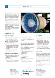
coMpReHenSi V e coMpetence in SeRVice<br />
anD Heat e XcH anG eRS<br />
More than 125 years of prod-<br />
uct competence, the innovative<br />
force of our inter national teams<br />
of ex perts as well as constant<br />
re search and development are<br />
the basis of our global power<br />
strategy.<br />
Advantages to our customers:<br />
Complete solutions and ser-<br />
vices from one single source –<br />
quick, flexible and efficient.<br />
Count on us and benefit from<br />
our product and service com-<br />
petence.<br />
RANGE OF PRODUCTS AND SERVICES<br />
Power plant components<br />
Development, design, manufacture,<br />
erection and commissioning of:<br />
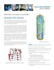
• Surface steam condensers<br />
• Feedwater heaters<br />
• Deaerators/feedwater tanks<br />
• Moisture separator reheaters<br />
• poWeRSep ® high velocity<br />
separators<br />
• poWeRVane ® chevron type<br />
separators<br />
Air and flue gas systems<br />
Development, design, manufacture,<br />
erection and commissioning of:<br />
• Regenerative air and gas<br />
heaters of the RotHe MÜHle ®<br />
and Ljungström types<br />
• Air pollution control equipment<br />
RotHeMÜHle ® design<br />
• bi-coRona ® electrostatic<br />
precipitators<br />
• Bag filters<br />
• Delta WinG ® static gas mixers<br />
for use in DeNOx systems and<br />
optimisation of dust collection<br />
efficiency in eSps<br />
Boiler services and general<br />
power plant services<br />
• Engineering<br />
• Manufacture<br />
• Erection<br />
• Maintenance and upkeep<br />
• Spare parts<br />
• Provision and management of<br />
overhaul services<br />
• Boiler modernisation and<br />
modification<br />
• Replacement and modernisation<br />
of power plant components as<br />
well as air and flue gas systems
<strong>Uprating</strong> <strong>Through</strong> <strong>Condenser</strong> <strong>Reconstruction</strong><br />
<strong>Uprating</strong> <strong>Through</strong> <strong>Condenser</strong> <strong>Reconstruction</strong><br />
J. Scheurlen, R. Scharf and W. Schulz<br />
Abstract<br />
<strong>Uprating</strong> <strong>Through</strong><br />
<strong>Condenser</strong> <strong>Reconstruction</strong><br />
Due to necessary modifications to the feed<br />
water chemistry at Stade nuclear power plant,<br />
the turbine condensers fitted with brass tubes<br />
have been converted to use austenitic cooling<br />
water tubes. At the same time, a completely<br />
new design of tube bundle and air<br />
cooling system has been installed. A significant<br />
improvement in heat transfer and considerably<br />
more effective air extraction and also<br />
increased net output by up to 4 MW have<br />
been attained using the new condenser.<br />
Kurzfassung<br />
Authors<br />
Leistungserhöhung durch<br />
Kondensatorumbau<br />
Durch die notwendige Änderung der Speisewasserchemie<br />
im Kernkraftwerk Stade wurden<br />
die mit Messingrohren ausgerüsteten<br />
Turbinenkondensatoren auf austenitische<br />
Kühlwasserrohre umgerüstet. Zugleich wurde<br />
eine völlig neue Konstruktion der Rohrbündel<br />
und des Luftkühlersystems eingesetzt. Mit<br />
dem neuen Kondensator wird eine deutlich<br />
bessere Wärmeübertragung und eine erheblich<br />
wirkungsvollere Luftabsaugung sowie eine<br />
um bis zu 4 MW gesteigerte Nettoleistung<br />
erreicht.<br />
Dipl.-Ing. J. Scheurlen<br />
Dr.-Ing. R. Scharf<br />
PreussenElektra AG<br />
Hanover/Germany<br />
Dipl.-Ing. W. Schulz<br />
<strong>Balcke</strong>-<strong>Dürr</strong> AG<br />
Ratingen/Germany<br />
In 1987, the operator of the Stade nuclear<br />
power plant (KKS) faced the task of adjusting<br />
the feedwater chemistry to higher ammonia<br />
(NH3) contents in order to create more favourable<br />
conditions for steam generator operation.<br />
This adjustment made it necessary to replace<br />
all the cupriferous materials in the steam circuit<br />
as it is a well-known fact that copper and<br />
ammonia are not compatible. The most extensive<br />
individual measure in connection with<br />
this material change involved the turbine condensers<br />
which have a total of 43,000 brass<br />
tubes (total length 570 km) and yellow metal<br />
tubesheets. Difficulties with ammonia corrosion<br />
occurred even with the relatively low<br />
NH3 contents of the previous mode of operation<br />
and this led to repairs having to be carried<br />
out. So-called air pockets, in which the<br />
non-condensable gases including an increased<br />
concentration of NH3 occurred, formed due to<br />
the unfavourable design of the tube fields.<br />
Various proposals were investigated as a preliminary<br />
step to the required reconstruction<br />
measures. The comparison in Ta b l e 1 shows<br />
that the concept involving completely prefabricated<br />
bundle modules (variant 6) could be<br />
implemented within an extremely short period,<br />
thus offering decisive cost advantages.<br />
The reconstruction times required for all variants<br />
involving retubing on the jobsite were<br />
considerably longer than the time required for<br />
manufacture in the workshop. Moreover, the<br />
poorer conductivity of the copper-free tube<br />
material would have meant a definite reduction<br />
in the turbo generator output if the tube<br />
layout remained unchanged. Operating experience<br />
with turbo generators which have been<br />
reconstructed in this way confirmed this [1].<br />
It is possible to avoid such undesirable loss of<br />
output when carrying out the reconstruction<br />
on the jobsite using a more up-to-date tube<br />
Table 1. Concepts for the reconstruction of the condenser in the KKS.<br />
layout, but only at the expense of significantly<br />
longer inspection times. The concept involving<br />
condensers completely prefabricated in<br />
the workshop (variant 5) also proved to be uneconomic.<br />
Design<br />
The thermodynamic design data were determined<br />
after checking how the turbo generator<br />
is used:<br />
Cooling water inlet temperature 9.8 °C<br />
Cooling water mass flow 4 x 7,425 kg/s<br />
Heat flow to be discharged 1,214 MW<br />
The external dimensions of the bundle modules<br />
were to a great extent determined by the<br />
existing condenser shell. A height limitation<br />
due to the concrete crossbeam of the power<br />
house made the situation more difficult.<br />
The optimum was found to be a cooling surface<br />
area of 37,820 m2 for the entire condenser<br />
with a tube outer diameter of 22 mm, a<br />
condenser pressure of 34.7 mbar thus being<br />
guaranteed.<br />
Titanium and stainless steel were considered<br />
as tube material.<br />
The advantages of titanium are:<br />
− somewhat better thermal conductivity<br />
− unsusceptibility to standstill corrosion<br />
The advantages of stainless steel are:<br />
− greater admissible spacing of the supporting<br />
walls,<br />
− lower price<br />
As no corrosion had occurred on the stainless<br />
steel tubes (material no 1.4439) used for re-<br />
1 2 3 4 5 6<br />
Measure Retubing and new tubesheets Prefabricated<br />
condensers<br />
(<strong>Condenser</strong><br />
modules)<br />
Tube layout Unchanged Modernised<br />
Manufacture Jobsite Workshop<br />
Prefabricated<br />
tube<br />
internals<br />
(Bundle<br />
modules)<br />
Outages x calendar days 2 x 81 1 x 97 2 x 100 1 x 122 2 x 50 1 x 39<br />
Turboset output Decrease Increase<br />
Cost factor 5.4 4.1 7.0 5.1 3.8 1<br />
3
<strong>Uprating</strong> <strong>Through</strong> <strong>Condenser</strong> <strong>Reconstruction</strong><br />
Figure 1. Bundle cross-section with flow pattern.<br />
1 steam pass 7 condensate collecting tray<br />
2 air pass 8 flat steel crossbeams<br />
3 horizontal tube field 9 longitudinal beams<br />
4 air cooler 10 screw bolts<br />
5 supporting wall 11 connecting tubes<br />
6 air cooler cover<br />
pair of the existing condensers, this material<br />
was also selected for the new condensers.<br />
4<br />
The Tube Bundle<br />
F i g u r e 1 shows a cross-section of the tube<br />
bundle. Noticeable features are the very simple<br />
overall shape and also the simplicity of the<br />
details. This shape permits an ideal flow. The<br />
velocity in the steam passes is virtually constant<br />
all the way down. The pressure loss due<br />
to friction is minimal. The velocity decreases<br />
in the lower section of the passes up to below<br />
the horizontal tube field. The transformation<br />
of the kinetic energy of the steam into static<br />
enthalpy is highly desirable in this section as<br />
the temperature and pressure increase caused<br />
by this improves condensation. More steam<br />
condenses on the cooling water inlet side than<br />
on the outlet side due to the greater temperature<br />
difference between the steam and the<br />
cooling water. In order not to impede this effect,<br />
large recesses are provided in the supporting<br />
walls to balance the flow in a longitudinal<br />
direction.<br />
The bundle arms become thicker as they go<br />
downwards to the beginning of the air pass<br />
(internal steam pass) and in this way provide<br />
the necessary pressure gradient in the direction<br />
of the air cooler. All paths leading there<br />
are very short. The somewhat subcooled condensate<br />
accumulating in the bundle rains onto<br />
the two collecting trays, flows from there<br />
out of the bundle in counterflow to the steam<br />
and is heated on the way. The collecting trays<br />
also prevent the external section in the lower<br />
tube field from being flooded. The heavily<br />
subcooled condensate enriched with air which<br />
flows out of the air cooler is heated and deaerated<br />
by the steam flowing upwards.<br />
The Bundle Module Support Structure<br />
A prerequisite for the design was that the rigidity<br />
and stability required to transport and<br />
install the prefabricated modules be achieved<br />
using as little material as possible and without<br />
disturbing the flow. Furthermore the connections<br />
between the condenser casing and<br />
the module should be easy to carry out. F i g -<br />
u r e s 1 and 2 show how the requirements<br />
could be met. Four flat steel beams (to which<br />
the crane girder is secured to relocate the<br />
modules), the two air cooler covers of a reinforced<br />
construction and the two lower longitudinal<br />
beams serve as reinforcement in the longitudinal<br />
direction. Only the two longitudinal<br />
beams are located in the steam flow but in areas<br />
with a relatively low velocity. Vacuum<br />
forces from the condenser side wall are transferred<br />
to the supporting walls of the module<br />
via weld-in joint tubes or via screw bolts in<br />
inaccessible areas. The spacing of the supporting<br />
walls ensures that no inadmissible<br />
tube vibrations occur even under the most unfavourable<br />
operating conditions.<br />
Figure 2. Bundle module – support structure.<br />
Figure 3. Welding the tubes to the<br />
clad tubesheet.<br />
Manufacture and Erection<br />
Especially stringent tightness requirements<br />
are placed on nuclear power plant condensers.<br />
A great deal of importance was attached to<br />
quality assurance when manufacturing the<br />
stainless steel tubes. The longitudinal joints<br />
were welded using fully automatic equipment<br />
and subjected to an eddy current examination.<br />
All tubes were also checked for tightness during<br />
a subsequent helium test.<br />
The quality of the explosion clad/roll bond<br />
clad tubesheets, the base material of which is<br />
boiler plate and the cladding material stainless<br />
steel, material no. 1.4439, exceeds the<br />
requirements set out in the AD standards. The<br />
boreholes in the tubesheets and the supporting<br />
walls were carried out with numerically controlled<br />
boring mills within precisely specified<br />
tolerances.
The four bundle modules were constructed in<br />
the <strong>Balcke</strong>-<strong>Dürr</strong> AG workshops in 1989. Optically<br />
aligned auxiliary equipment was used<br />
for the precision construction of the support<br />
structure. The condenser tubes could be easily<br />
inserted through the tubesheets and the 17<br />
supporting walls. All tubes are rolled into<br />
the tubesheets. An automated TIG pulsation<br />
welding method was used to make the weld<br />
joint between the tubes and the tubesheet<br />
( F i g u r e 3 ) . The forces occurring between<br />
the tube and the tubesheet are discharged via<br />
the rolled joints. The purpose of the weld is<br />
solely to ensure that the tube/tubesheet joint is<br />
absolutely tight. The 100 % roll-in and dye<br />
penetrant examinations carried out on these<br />
welds together with the random X-ray examination<br />
using microfocus equipment rule out<br />
any discontinuities.<br />
Workshop prefabrication of complete bundle<br />
modules ready for installation offers two significant<br />
advantages:<br />
− the plant is at a standstill for less time and<br />
− manufacture is carried out under more favourable<br />
conditions due to the existing<br />
infrastructure being used.<br />
With respect to the transportation of the modules,<br />
there was basically a choice between<br />
Figure 4. Dismantling of the existing condenser fill.<br />
combined boat and road transport or just road<br />
transport. Preference was given to road transport<br />
so as not to jeopardize the delivery date<br />
should the waterways freeze. Each module<br />
measuring approx. 4,400 mm x 4,500 mm and<br />
13,300 mm and weighing approx. 80 tons<br />
could be transported to the power station in<br />
24 hours without any difficulties.<br />
In the plans for the replacement of the four<br />
condenser halves, the new bundle modules<br />
were scheduled to arrive before the intended<br />
power station shutdown so that interim storage<br />
was necessary.<br />
Preliminary work such as fortification of the<br />
entry roads to the interim storage areas, setting<br />
up the crane facilities, the installation of<br />
the positioning rails and the equipping of the<br />
site workshop could be carried out before the<br />
modules were supplied. When the power station<br />
was shut down for inspection in 1990,<br />
only the remaining work in the area between<br />
<strong>Uprating</strong> <strong>Through</strong> <strong>Condenser</strong> <strong>Reconstruction</strong><br />
the power house wall and the condensers had<br />
still to be carried out. The cooling water hoods<br />
were removed and stored in the power house<br />
during the reconstruction work. It was then<br />
possible to detach all the internals from the<br />
existing condensers and to remove them<br />
through the openings in the power house wall<br />
( F i g u r e 4 ) . The positioning rails required<br />
to move the bundles in a longitudinal and<br />
transverse direction were then installed in the<br />
condenser casing. Within three days the four<br />
bundle modules were collected from the interim<br />
storage area and, with the help of a flat<br />
carriage and a crane, placed on the positioning<br />
rails (Figure 5), drawn in by winches and<br />
moved in a transverse direction. After having<br />
been precisely aligned, the bundle modules<br />
were secured in the casing via various welded<br />
and bolted joints and the cooling water hoods<br />
screwed on again.<br />
The times provided for the reconstruction of<br />
the two part condensers in the 1990 inspec-<br />
Figure 5. Placing a module on the positioning rails.<br />
DP in MW<br />
4<br />
3<br />
2<br />
1<br />
0<br />
* At 100 % reactor output<br />
At 100 % cooling water mass flow<br />
0 5 10 15 20 25<br />
q W1 in °C<br />
Figure 6. Calculated increase in output as a result of the reconstruction<br />
of the condensers.<br />
∆P = change in the electric output<br />
ϑ W1 = cooling water inlet temperature<br />
5
<strong>Uprating</strong> <strong>Through</strong> <strong>Condenser</strong> <strong>Reconstruction</strong><br />
tion schedule were fully complied with. The<br />
reconstruction could be completed ready for<br />
service within 39 days with the work being<br />
carried out in two shifts.<br />
6<br />
Measurements on the <strong>Condenser</strong>s<br />
The measuring equipment required to determine<br />
the heat transfer coefficient was installed<br />
and tested a year before the reconstruction of<br />
the condenser. Long-term stability was required<br />
in addition to a great degree of precision<br />
because this equipment is subsequently<br />
to be used to monitor the condenser. Therefore<br />
the temperature measurement as per the<br />
VGB Directive [2] was selected instead of the<br />
exhaust steam pressure measurement which is<br />
problematic when applied for this purpose.<br />
The temperature measurement is carried out<br />
using a specially developed probe which is insensitive<br />
to changes in the direction and the<br />
velocity of the flow. Each condenser is provided<br />
with four probes, two each on the cooling<br />
water inlet side and outlet side, located<br />
approx. 0.5 m above the tubing.<br />
Ten pressure measuring points mounted on<br />
the periphery of each condenser half were<br />
used to measure the condenser pressure for<br />
the acceptance tests.<br />
The temperatures of the four cooling water<br />
trains are measured in the two ball return lines<br />
to the collecting trays of the condenser tube<br />
cleaning system on the outlet side where the<br />
formation of strands is to be expected. This<br />
simple solution has proved very effective. It<br />
is, however, necessary for the recirculation<br />
pumps to be running during the measurement.<br />
The cooling water inlet temperatures are<br />
measured once in each train immediately before<br />
the condenser.<br />
p in mbar<br />
q S – q G in K<br />
54<br />
52<br />
50<br />
48<br />
46<br />
44<br />
42<br />
40<br />
38<br />
36<br />
15<br />
10<br />
5<br />
0<br />
m<br />
·<br />
L = 9.4 kg/h<br />
Resistance thermometers Pt 100 with 1/3 DIN<br />
tolerance and four-wire connection, a diameter<br />
of 6 mm and uniform length of 300 mm<br />
are used as measuring probes at all measuring<br />
points. The thermometers are not in thermometer<br />
wells but in the medium flow. Clamped<br />
joints with teflon rings are used to secure and<br />
seal the thermometers.<br />
Acceptance Measurements<br />
Measurements were carried out soon after the<br />
power generating unit had been recommissioned<br />
to prove the guaranteed performance<br />
values.<br />
The following results were obtained:<br />
− The condenser pressure was 1.2 mbar below<br />
the guaranteed value.<br />
− The condensate subcooling was 0 to 0.5 K<br />
(guaranteed value < 1 K).<br />
m<br />
·<br />
L = 47.7 kg/h<br />
I II III IV I II III IV<br />
Figure 7. Curves of the measured axial pressure and subcooling.<br />
m˙ L = leakage air mass flow<br />
p = pressure<br />
ϑ s - ϑ G = mixture subcooling<br />
(q S – q G) or (q G – q W1) in K x O 2 in mg/kg k<br />
1.0<br />
0.9<br />
0.8<br />
6<br />
4<br />
2<br />
0<br />
18<br />
16<br />
14<br />
12<br />
10<br />
8<br />
6<br />
4<br />
2<br />
0<br />
− The O2<br />
content in the condenser was approx.<br />
1 µg/kg (guaranteed value < 10 µg/<br />
kg).<br />
The new condensers achieve an increased net<br />
output in particular during the summer when<br />
the cooling water inlet temperatures are high<br />
(Figure 6).<br />
Test Measurements<br />
One bundle was equipped with test instruments<br />
to check the effective functioning<br />
of the condenser. The arrangement of the<br />
measuring points and the position of the four<br />
measuring levels are shown at the top of F i g -<br />
u r e 7 . Below that is an example of the pressure<br />
and mixture subcooling values measured<br />
at two different leakage air mass flows in a<br />
part condenser. If the corresponding pressure<br />
curves of the two leakage air flows are com-<br />
q S – q G<br />
q G – q W1<br />
0 10 20 30 40 50 60<br />
m<br />
·<br />
L in kg/h<br />
Figure 8. Parameters for changed leakage air mass flow.<br />
� = efficient evacuation pump<br />
+ = defective evacuation pump<br />
k = relative heat transfer coefficient<br />
x . O 2 = oxygen content of the condensate<br />
ϑ s - ϑ G = mixture subcooling<br />
ϑ s = saturation temperature<br />
ϑ G = mixture temperature<br />
ϑ G - ϑ W1 = mixture excess temperature<br />
ϑ W1 = cooling water inlet temperature
pared, only minimal differences are found up<br />
to the air cooler inlet; only the pressure level<br />
of the greater leakage air flow is approx. 2<br />
mbar higher. The pressure drops in the air<br />
cooler are still approximately the same at<br />
measuring levels IV and III, ample steam still<br />
flows and condenses, the partial pressure of<br />
the air is low.<br />
That means that no undesirable air accumulations<br />
occur here. There is therefore a proper<br />
axial air flow to the suction point on the cooling<br />
water inlet side.<br />
The pressure drop of the greater leakage air<br />
flow does not fall to almost zero until this air<br />
flow reaches measuring levels II and I: only a<br />
little steam still flows and the partial pressure<br />
of the air is high. As required, the air accumulates<br />
before the suction point.<br />
The changes can be seen even more clearly in<br />
the subcooling curve. At measuring levels IV<br />
and III the mixture subcooling in only approx. 1<br />
K. It then rises steeply to over 13 K at measuring<br />
level I. Not only is this unusually high value surprising<br />
but even more so the fact that the steam/<br />
air mixture is cooled down almost to the cooling<br />
water inlet temperature. The mixture subcooling<br />
and therefore the extractable air mass flow<br />
almost reach the theoretical maximum. The<br />
most important parameters from two series of<br />
measurements are shown in F i g u r e 8 as a<br />
function of the leakage air mass flow.<br />
One series of measurements was carried out using<br />
an evacuation pump running at low capacity<br />
and the other series with an evacuation pump<br />
operating at normal capacity. The evacuation<br />
pump used in each case extracted air from both<br />
part condensers as it was not possible to separate<br />
the suction line. During the measurements,<br />
the part condenser fitted with instruments was<br />
charged with changed air mass flows (design<br />
value for the evacuation system according to<br />
VGB Recommendation [3]: 10.8 kg/h).<br />
It is very obvious that the drop in the K value<br />
and the O2 increase occur simultaneously but<br />
only when the steam/air mixture in the air<br />
cooler has almost reached its lowest temperature.<br />
The excess temperature diagram shows<br />
particularly clearly when this lowest possible<br />
temperature is reached.<br />
The generally extremely low O2 content in the<br />
condensate and its slow increase as a function<br />
of the air mass flow rate are particularly noticeable<br />
during air extraction as per the design<br />
values.<br />
<strong>Uprating</strong> <strong>Through</strong> <strong>Condenser</strong> <strong>Reconstruction</strong><br />
The series of measurements with the evacuation<br />
pump running at a low capacity yielded<br />
condensate subcooling values of between 0.2<br />
and – 0.1 K at all leakage air mass flows. The<br />
condensate subcooling was not measured during<br />
the series of measurements with pumps<br />
functioning normally.<br />
The high efficiency of the bundle permits a<br />
drastic reduction in the size of the evacuation<br />
pumps due to the higher air content in the<br />
mixture or it enables large air ingresses to be<br />
controlled without impairing the condenser<br />
vacuum.<br />
References<br />
[1] GKN-1: Nennleistung reduziert. Atomwirtschaft,<br />
Nachrichten des Monats, Februar 1991,<br />
S. 49.<br />
[2] VGB-Richtlinie „Bestimmung des Wärmedurchgangskoeffizienten<br />
von wassergekühlten<br />
Oberflächenkondensatoren“. VGB-KRAFT-<br />
WERKSTECHNIK GmbH, Essen (in Vorbereitung).<br />
[3] VGB-Empfehlung für Auslegung und Betrieb<br />
von Vakuumpumpen bei Dampfturbinen-<br />
Kondensatoren. VGB-R 126 L. Ausgabe 1986.<br />
VGB-KRAFTWERKSTECHNIK GmbH,<br />
Essen.<br />
7
ouR SeRViceS W o R l DWi D e<br />
<strong>Balcke</strong>-<strong>Dürr</strong> GmbH<br />
Ernst-Dietrich-Platz 2<br />
40882 Ratingen, Germany<br />
Tel.: +49 (0) 2102 1669 -0<br />
Fax: +49 (0) 2102 1669 -617<br />
bdinfode@cts.spx.com<br />
www.balcke-duerr.com<br />
BRANCH OFFICE<br />
ROTHEMÜHLE<br />
<strong>Balcke</strong>-<strong>Dürr</strong> GmbH<br />
Wildenburger Strasse 1<br />
57482 Wenden, Germany<br />
Tel.: +49 (0) 2762 611-0<br />
Fax: +49 (0) 2762 611-297<br />
bdinform@cts.spx.com<br />
www.balcke-duerr.de<br />
Further companies in: China, Italy, Poland, South Africa, Hungary