FOXBOX Tx/Rx VGA, VGA/YUV, DVI, and - Extron Electronics
FOXBOX Tx/Rx VGA, VGA/YUV, DVI, and - Extron Electronics
FOXBOX Tx/Rx VGA, VGA/YUV, DVI, and - Extron Electronics

Create successful ePaper yourself
Turn your PDF publications into a flip-book with our unique Google optimized e-Paper software.
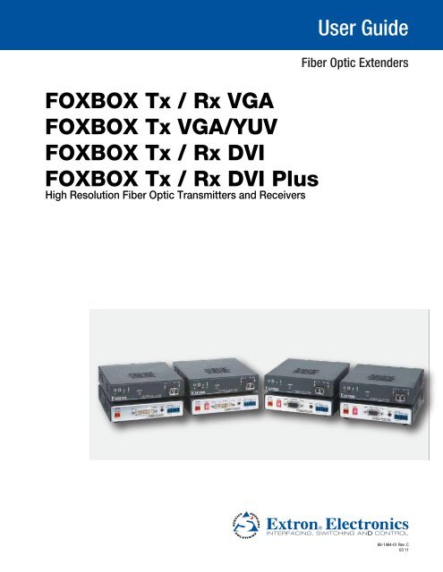
<strong>FOXBOX</strong> <strong>Tx</strong> / <strong>Rx</strong> <strong>VGA</strong><br />
<strong>FOXBOX</strong> <strong>Tx</strong> <strong>VGA</strong>/<strong>YUV</strong><br />
<strong>FOXBOX</strong> <strong>Tx</strong> / <strong>Rx</strong> <strong>DVI</strong><br />
<strong>FOXBOX</strong> <strong>Tx</strong> / <strong>Rx</strong> <strong>DVI</strong> Plus<br />
High Resolution Fiber Optic Transmitters <strong>and</strong> Receivers<br />
User Guide<br />
Fiber Optic Extenders<br />
68-1464-01 Rev. C<br />
03 11
Safety Instructions • English<br />
This symbol is intended to alert the user of important operating <strong>and</strong> maintenance<br />
(servicing) instructions in the literature provided with the equipment.<br />
This symbol is intended to alert the user of the presence of uninsulated<br />
dangerous voltage within the product’s enclosure that may present a risk of<br />
electric shock.<br />
Caution<br />
Read Instructions • Read <strong>and</strong> underst<strong>and</strong> all safety <strong>and</strong> operating instructions before using the equipment.<br />
Retain Instructions • The safety instructions should be kept for future reference.<br />
Follow Warnings • Follow all warnings <strong>and</strong> instructions marked on the equipment or in the user information.<br />
Avoid Attachments • Do not use tools or attachments that are not recommended by the equipment<br />
manufacturer because they may be hazardous.<br />
Consignes de Sécurité • Français<br />
Ce symbole sert à avertir l’utilisateur que la documentation fournie avec le<br />
matériel contient des instructions importantes concernant l’exploitation et la<br />
maintenance (réparation).<br />
Ce symbole sert à avertir l’utilisateur de la présence dans le boîtier<br />
de l’appareil de tensions dangereuses non isolées posant des risques<br />
d’électrocution.<br />
Attention<br />
Lire les instructions• Prendre connaissance de toutes les consignes de sécurité et d’exploitation avant<br />
d’utiliser le matériel.<br />
Conserver les instructions• Ranger les consignes de sécurité afin de pouvoir les consulter à l’avenir.<br />
Respecter les avertissements • Observer tous les avertissements et consignes marqués sur le matériel ou<br />
présentés dans la documentation utilisateur.<br />
Eviter les pièces de fixation • Ne pas utiliser de pièces de fixation ni d’outils non recomm<strong>and</strong>és par le<br />
fabricant du matériel car cela risquerait de poser certains dangers.<br />
Sicherheitsanleitungen • Deutsch<br />
Dieses Symbol soll dem Benutzer in der im Lieferumfang enthaltenen<br />
Dokumentation besonders wichtige Hinweise zur Bedienung und Wartung<br />
(Inst<strong>and</strong>haltung) geben.<br />
Dieses Symbol soll den Benutzer darauf aufmerksam machen, daß im Inneren<br />
des Gehäuses dieses Produktes gefährliche Spannungen, die nicht isoliert sind<br />
und die einen elektrischen Schock verursachen können, herrschen.<br />
Achtung<br />
Lesen der Anleitungen • Bevor Sie das Gerät zum ersten Mal verwenden, sollten Sie alle Sicherheits-und<br />
Bedienungsanleitungen genau durchlesen und verstehen.<br />
Aufbewahren der Anleitungen • Die Hinweise zur elektrischen Sicherheit des Produktes sollten Sie<br />
aufbewahren, damit Sie im Bedarfsfall darauf zurückgreifen können.<br />
Befolgen der Warnhinweise • Befolgen Sie alle Warnhinweise und Anleitungen auf dem Gerät oder in der<br />
Benutzerdokumentation.<br />
Keine Zusatzgeräte • Verwenden Sie keine Werkzeuge oder Zusatzgeräte, die nicht ausdrücklich vom<br />
Hersteller empfohlen wurden, da diese eine Gefahrenquelle darstellen können.<br />
Instrucciones de seguridad • Español<br />
Este símbolo se utiliza para advertir al usuario sobre instrucciones importantes<br />
de operación y mantenimiento (o cambio de partes) que se desean<br />
destacar en el contenido de la documentación suministrada con los equipos.<br />
Este símbolo se utiliza para advertir al usuario sobre la presencia de elementos<br />
con voltaje peligroso sin protección aislante, que puedan encontrarse<br />
dentro de la caja o alojamiento del producto, y que puedan representar<br />
riesgo de electrocución.<br />
Precaucion<br />
Leer las instrucciones • Leer y analizar todas las instrucciones de operación y seguridad, antes de usar el<br />
equipo.<br />
Conservar las instrucciones • Conservar las instrucciones de seguridad para futura consulta.<br />
Obedecer las advertencias • Todas las advertencias e instrucciones marcadas en el equipo o en la<br />
documentación del usuario, deben ser obedecidas.<br />
安全须知 • 中文<br />
这个符号提示用户该设备用户手册中有重要的操作和维护说明。<br />
这个符号警告用户该设备机壳内有暴露的危险电压,有触电危险。<br />
注意<br />
阅读说明书 • 用户使用该设备前必须阅读并理解所有安全和使用说明。<br />
保存说明书 • 用户应保存安全说明书以备将来使用。<br />
遵守警告 • 用户应遵守产品和用户指南上的所有安全和操作说明。<br />
避免追加 • 不要使用该产品厂商没有推荐的工具或追加设备,以避免危险。<br />
Warning<br />
Power sources • This equipment should be operated only from the power source indicated on the product. This<br />
equipment is intended to be used with a main power system with a grounded (neutral) conductor. The third<br />
(grounding) pin is a safety feature, do not attempt to bypass or disable it.<br />
Power disconnection • To remove power from the equipment safely, remove all power cords from the rear of<br />
the equipment, or the desktop power module (if detachable), or from the power source receptacle (wall plug).<br />
Power cord protection • Power cords should be routed so that they are not likely to be stepped on or pinched<br />
by items placed upon or against them.<br />
Servicing • Refer all servicing to qualified service personnel. There are no user-serviceable parts inside. To prevent<br />
the risk of shock, do not attempt to service this equipment yourself because opening or removing covers may<br />
expose you to dangerous voltage or other hazards.<br />
Slots <strong>and</strong> openings • If the equipment has slots or holes in the enclosure, these are provided to prevent<br />
overheating of sensitive components inside. These openings must never be blocked by other objects.<br />
Lithium battery • There is a danger of explosion if battery is incorrectly replaced. Replace it only with the<br />
same or equivalent type recommended by the manufacturer. Dispose of used batteries according to the<br />
manufacturer’s instructions.<br />
Avertissement<br />
Alimentations • Ne faire fonctionner ce matériel qu’avec la source d’alimentation indiquée sur l’appareil. Ce<br />
matériel doit être utilisé avec une alimentation principale comportant un fil de terre (neutre). Le troisième<br />
contact (de mise à la terre) constitue un dispositif de sécurité : n’essayez pas de la contourner ni de la<br />
désactiver.<br />
Déconnexion de l’alimentation• Pour mettre le matériel hors tension sans danger, déconnectez tous les<br />
cordons d’alimentation de l’arrière de l’appareil ou du module d’alimentation de bureau (s’il est amovible) ou<br />
encore de la prise secteur.<br />
Protection du cordon d’alimentation • Acheminer les cordons d’alimentation de manière à ce que personne<br />
ne risque de marcher dessus et à ce qu’ils ne soient pas écrasés ou pincés par des objets.<br />
Réparation-maintenance • Faire exécuter toutes les interventions de réparation-maintenance par un<br />
technicien qualifié. Aucun des éléments internes ne peut être réparé par l’utilisateur. Afin d’éviter tout danger<br />
d’électrocution, l’utilisateur ne doit pas essayer de procéder lui-même à ces opérations car l’ouverture ou le<br />
retrait des couvercles risquent de l’exposer à de hautes tensions et autres dangers.<br />
Fentes et orifices • Si le boîtier de l’appareil comporte des fentes ou des orifices, ceux-ci servent à empêcher les<br />
composants internes sensibles de surchauffer. Ces ouvertures ne doivent jamais être bloquées par des objets.<br />
Lithium Batterie • Il a danger d’explosion s’ll y a remplacment incorrect de la batterie. Remplacer uniquement<br />
avec une batterie du meme type ou d’un ype equivalent recomm<strong>and</strong>e par le constructeur. Mettre au reut les<br />
batteries usagees conformement aux instructions du fabricant.<br />
Vorsicht<br />
Stromquellen • Dieses Gerät sollte nur über die auf dem Produkt angegebene Stromquelle betrieben werden.<br />
Dieses Gerät wurde für eine Verwendung mit einer Hauptstromleitung mit einem geerdeten (neutralen) Leiter<br />
konzipiert. Der dritte Kontakt ist für einen Erdanschluß, und stellt eine Sicherheitsfunktion dar. Diese sollte nicht<br />
umgangen oder außer Betrieb gesetzt werden.<br />
Stromunterbrechung • Um das Gerät auf sichere Weise vom Netz zu trennen, sollten Sie alle Netzkabel aus der<br />
Rückseite des Gerätes, aus der externen Stomversorgung (falls dies möglich ist) oder aus der W<strong>and</strong>steckdose<br />
ziehen.<br />
Schutz des Netzkabels • Netzkabel sollten stets so verlegt werden, daß sie nicht im Weg liegen und niem<strong>and</strong><br />
darauf treten kann oder Objekte darauf- oder unmittelbar dagegengestellt werden können.<br />
Wartung • Alle Wartungsmaßnahmen sollten nur von qualifiziertem Servicepersonal durchgeführt werden.<br />
Die internen Komponenten des Gerätes sind wartungsfrei. Zur Vermeidung eines elektrischen Schocks<br />
versuchen Sie in keinem Fall, dieses Gerät selbst öffnen, da beim Entfernen der Abdeckungen die Gefahr eines<br />
elektrischen Schlags und/oder <strong>and</strong>ere Gefahren bestehen.<br />
Schlitze und Öffnungen • Wenn das Gerät Schlitze oder Löcher im Gehäuse aufweist, dienen diese zur<br />
Vermeidung einer Überhitzung der empfindlichen Teile im Inneren. Diese Öffnungen dürfen niemals von<br />
<strong>and</strong>eren Objekten blockiert werden.<br />
Litium-Batterie • Explosionsgefahr, falls die Batterie nicht richtig ersetzt wird. Ersetzen Sie verbrauchte Batterien<br />
nur durch den gleichen oder einen vergleichbaren Batterietyp, der auch vom Hersteller empfohlen wird.<br />
Entsorgen Sie verbrauchte Batterien bitte gemäß den Herstelleranweisungen.<br />
Evitar el uso de accesorios • No usar herramientas o accesorios que no sean especificamente recomendados<br />
por el fabricante, ya que podrian implicar riesgos.<br />
Advertencia<br />
Alimentación eléctrica • Este equipo debe conectarse únicamente a la fuente/tipo de alimentación eléctrica<br />
indicada en el mismo. La alimentación eléctrica de este equipo debe provenir de un sistema de distribución<br />
general con conductor neutro a tierra. La tercera pata (puesta a tierra) es una medida de seguridad, no<br />
puentearia ni eliminaria.<br />
Desconexión de alimentación eléctrica • Para desconectar con seguridad la acometida de alimentación<br />
eléctrica al equipo, desenchufar todos los cables de alimentación en el panel trasero del equipo, o desenchufar<br />
el módulo de alimentación (si fuera independiente), o desenchufar el cable del receptáculo de la pared.<br />
Protección del cables de alimentación • Los cables de alimentación eléctrica se deben instalar en lugares<br />
donde no sean pisados ni apretados por objetos que se puedan apoyar sobre ellos.<br />
Reparaciones/mantenimiento • Solicitar siempre los servicios técnicos de personal calificado. En el interior no<br />
hay partes a las que el usuario deba acceder. Para evitar riesgo de electrocución, no intentar personalmente la<br />
reparación/mantenimiento de este equipo, ya que al abrir o extraer las tapas puede quedar expuesto a voltajes<br />
peligrosos u otros riesgos.<br />
Ranuras y aberturas • Si el equipo posee ranuras o orificios en su caja/alojamiento, es para evitar el<br />
sobrecalientamiento de componentes internos sensibles. Estas aberturas nunca se deben obstruir con otros<br />
objetos.<br />
Batería de litio • Existe riesgo de explosión si esta batería se coloca en la posición incorrecta. Cambiar esta<br />
batería únicamente con el mismo tipo (o su equivalente) recomendado por el fabricante. Desachar las baterías<br />
usadas siguiendo las instrucciones del fabricante.<br />
警告<br />
电源 • 该设备只能使用产品上标明的电源。 设备必须使用有地线的供电系统供电。 第三条线<br />
(地线)是安全设施,不能不用或跳过 。<br />
拔掉电源 • 为安全地从设备拔掉电源,请拔掉所有设备后或桌面电源的电源线,或任何接到市<br />
电系统的电源线。<br />
电源线保护 • 妥善布线, 避免被踩踏,或重物挤压。<br />
维护 • 所有维修必须由认证的维修人员进行。 设备内部没有用户可以更换的零件。为避免出现<br />
触电危险不要自己试图打开设备盖子维修该设备。<br />
通风孔 • 有些设备机壳上有通风槽或孔,它们是用来防止机内敏感元件过热。 不要用任何东<br />
西挡住通风孔。<br />
锂电池 • 不正确的更换电池会有爆炸的危险。必须使用与厂家推荐的相同或相近型号的电池。<br />
按照生产厂的建议处理废弃电池。
FCC Class A Notice<br />
This equipment has been tested <strong>and</strong> found to comply with the limits for a Class A digital device, pursuant to part 15<br />
of the FCC Rules. Operation is subject to the following two conditions:<br />
1. This device may not cause harmful interference.<br />
2. This device must accept any interference received, including interference that may cause undesired operation.<br />
The Class A limits are designed to provide reasonable protection against harmful interference when the equipment is<br />
operated in a commercial environment. This equipment generates, uses, <strong>and</strong> can radiate radio frequency energy <strong>and</strong>,<br />
if not installed <strong>and</strong> used in accordance with the instruction manual, may cause harmful interference to radio communications.<br />
Operation of this equipment in a residential area is likely to cause harmful interference, in which case the<br />
user will be required to correct the interference at his own expense.<br />
NOTE: This unit was tested with shielded cables on the peripheral devices. Shielded cables must be used with<br />
the unit to ensure compliance with FCC emissions limits.<br />
For more information on safety guidelines, regulatory compliances, EMI/EMF compliance, accessibility, <strong>and</strong><br />
related topics, click here.<br />
Copyright<br />
© 2011 <strong>Extron</strong> <strong>Electronics</strong>. All rights reserved.<br />
Trademarks<br />
All trademarks mentioned in this guide are the properties of their respective owners.
Conventions Used in this Guide<br />
In this user guide, the following are used:<br />
NOTE: A note draws attention to important information.<br />
TIP: A tip provides a suggestion to make working with the application easier.<br />
CAUTION: A caution indicates a potential hazard to equipment or data.<br />
WARNING: A warning warns of things or actions that might cause injury, death, or<br />
other severe consequences.<br />
Comm<strong>and</strong>s are written in the fonts shown here:<br />
^AR Merge Scene,,Op1 scene 1,1 ^B 51 ^W^C<br />
[01] R 0004 00300 00400 00800 00600 [02] 35 [17] [03]<br />
E X! *X2@* X2$* X2$* X2% CE}<br />
NOTE: For comm<strong>and</strong>s <strong>and</strong> examples of computer or device responses mentioned<br />
in this guide, the character “0” is used for the number zero <strong>and</strong> “O”<br />
represents the capital letter “o.”<br />
Computer responses <strong>and</strong> directory paths that do not have variables are written in the font<br />
shown here:<br />
Reply from 208.132.180.48: bytes=32 times=2ms TTL=32<br />
C:\Program Files\<strong>Extron</strong><br />
Variables are written in slanted form as shown here:<br />
ping xxx.xxx.xxx.xxx —t<br />
SOH R Data STX Comm<strong>and</strong> ETB ETX<br />
Selectable items, such as menu names, menu options, buttons, tabs, <strong>and</strong> field names are<br />
written in the font shown here:<br />
From the File menu, select New.<br />
Click the OK button.
Contents<br />
Introduction ............................................ 1<br />
About the <strong>FOXBOX</strong> <strong>Tx</strong>/<strong>Rx</strong> Transmitters <strong>and</strong><br />
Receivers ........................................................ 2<br />
General System Operation ........................... 3<br />
System Compatibility ................................... 4<br />
Cable Transmission Modes ........................... 5<br />
Features ........................................................... 5<br />
Installation <strong>and</strong> Operation ..................... 7<br />
Installation Overview ........................................ 7<br />
Mounting the Unit ........................................... 7<br />
Connections <strong>and</strong> Configuration ....................... 8<br />
Transmitter Connections <strong>and</strong> Indicators ........ 8<br />
Receiver Connections <strong>and</strong> Indicators .......... 11<br />
Making Connections .................................. 14<br />
Operation ...................................................... 18<br />
Remote Control ......................................19<br />
Simple Instruction Set Control ........................ 20<br />
Host-to-Unit Instructions ............................ 20<br />
Symbol Definitions ..................................... 20<br />
Unit-initiated Messages .............................. 21<br />
Error Responses.......................................... 22<br />
Using the Comm<strong>and</strong>/Response Tables ........ 22<br />
FOX Extenders Control Program ..................... 27<br />
Installing the Software ............................... 27<br />
Starting the Program .................................. 27<br />
Firmware upgrade ...................................... 33<br />
Reference Information ..........................37<br />
Specifications ................................................. 37<br />
Part Numbers ................................................. 41<br />
<strong>FOXBOX</strong> <strong>Tx</strong>/<strong>Rx</strong> Part Numbers ...................... 41<br />
Included parts ............................................ 41<br />
Mounting Accessories ................................ 42<br />
Accessories ................................................ 42<br />
Mounting the Transmitter <strong>and</strong> Receiver .......... 43<br />
Tabletop Use .............................................. 43<br />
Mounting .................................................. 43<br />
<strong>FOXBOX</strong> <strong>Tx</strong>/<strong>Rx</strong> • Contents v
<strong>FOXBOX</strong> <strong>Tx</strong>/<strong>Rx</strong> • Contents vi
Introduction<br />
WARNING: The <strong>FOXBOX</strong> <strong>Tx</strong>/<strong>Rx</strong> units output continuous invisible light, which may be<br />
harmful to the eyes; use with caution.<br />
• Do not look into the rear panel fiber optic cable connectors or into<br />
the fiber optic cables themselves.<br />
• Plug the attached dust caps into the optical transceivers when the fiber<br />
cable is unplugged.<br />
• About the <strong>FOXBOX</strong> <strong>Tx</strong>/<strong>Rx</strong> Transmitters <strong>and</strong> Receivers<br />
• Features<br />
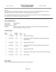
This manual contains information about the <strong>Extron</strong> <strong>FOXBOX</strong> family of fiber optic products.<br />
The <strong>FOXBOX</strong> family supports long distance transmission of <strong>VGA</strong>, <strong>YUV</strong>, <strong>and</strong> <strong>DVI</strong> video <strong>and</strong><br />
analog audio signals (see figure 1).<br />
RS-232<br />
<strong>FOXBOX</strong><br />
Control<br />
<strong>Extron</strong><br />
<strong>FOXBOX</strong> <strong>Tx</strong> <strong>VGA</strong><br />
Fiber Optic Transmitter<br />
POWER<br />
12V<br />
1.0A MAX<br />
RGB INPUT<br />
AUDIO<br />
<strong>FOXBOX</strong> 4G <strong>Tx</strong> <strong>VGA</strong><br />
RS-232<br />
OVER FIBER ALARM<br />
<strong>Tx</strong> <strong>Rx</strong> 1 2<br />
Up to 30 km (18.75 miles)<br />
singlemode �ber<br />
SM Model<br />
Optional Second<br />
Link for<br />
Box to Box<br />
Communications<br />
RS-232<br />
Projector<br />
Control<br />
POWER MODE<br />
12V<br />
1.0A MAX<br />
<strong>Extron</strong><br />
<strong>FOXBOX</strong> <strong>Rx</strong> <strong>VGA</strong><br />
Fiber Optic Receiver<br />
Figure 1. Typical <strong>FOXBOX</strong> <strong>Tx</strong>/<strong>Rx</strong> Application<br />
PC<br />
RGB OUTPUT<br />
AUDIO<br />
<strong>FOXBOX</strong> 4G <strong>Rx</strong> <strong>VGA</strong><br />
RS-232<br />
OVER FIBER ALARM<br />
<strong>Tx</strong> <strong>Rx</strong> 1 2<br />
<strong>Extron</strong><br />
MPA 122<br />
Mini Power<br />
Ampli�er<br />
Audio<br />
Output<br />
POWER<br />
L<br />
R<br />
INPUTS<br />
<strong>Extron</strong><br />
SI 26X<br />
Two-way Ceiling<br />
Speakers<br />
C US<br />
OUTPUTS<br />
4/8 Ohms<br />
REMOTE<br />
L R L R<br />
10V<br />
VOL/MUTE<br />
MPA 122<br />
RS-232<br />
Projector<br />
<strong>FOXBOX</strong> <strong>Tx</strong>/<strong>Rx</strong> • Introduction 1
About the <strong>FOXBOX</strong> <strong>Tx</strong>/<strong>Rx</strong> Transmitters <strong>and</strong> Receivers<br />
The <strong>FOXBOX</strong> family consists of the following ultra-high performance fiber optic transmitters<br />
<strong>and</strong> receivers:<br />
• <strong>FOXBOX</strong> <strong>Tx</strong> <strong>VGA</strong> transmitter — Accepts an analog RGB video input, an audio input,<br />
<strong>and</strong> an RS-232 serial input <strong>and</strong> outputs a proprietary optical signal on an LC connector<br />
to a <strong>FOXBOX</strong> or FOX 500 receiver. It also can receive a proprietary optical signal from the<br />
receiver consisting of the RS-232 return from a controlled device.<br />
• <strong>FOXBOX</strong> <strong>Tx</strong> <strong>VGA</strong>/<strong>YUV</strong> transmitter — Similar to the <strong>FOXBOX</strong> <strong>Tx</strong> <strong>VGA</strong>, but with the<br />
ability to support bi-level <strong>and</strong> tri-level <strong>YUV</strong> formats such as the 480p, 576p, 720p,<br />
1080i, <strong>and</strong> 1080p HDTV rates. It can also accept RGBHV video.<br />
• <strong>FOXBOX</strong> <strong>Rx</strong> <strong>VGA</strong> receiver — Accepts a proprietary optical signal on an LC connector<br />
from a <strong>FOXBOX</strong> (except <strong>FOXBOX</strong> <strong>Tx</strong> <strong>DVI</strong> Plus) or FOX 500 transmitter or daisy-chained<br />
receiver <strong>and</strong> outputs analog RGB or component video, audio, <strong>and</strong> RS-232 serial<br />
comm<strong>and</strong>s. It also can either:<br />
• Receive an RS-232 return from a controlled device <strong>and</strong> send it to the transmitter via<br />
a proprietary optical signal.<br />
• Output a daisy-chained signal to another receiver.<br />
• <strong>FOXBOX</strong> <strong>Tx</strong> <strong>DVI</strong> Plus transmitter — Accepts a single link of <strong>DVI</strong> video input (up<br />
to 1920 x 1200 at 60 Hz), an audio input, <strong>and</strong> an RS-232 serial input <strong>and</strong> outputs a<br />
proprietary optical signal on an LC connector to a <strong>FOXBOX</strong> <strong>Rx</strong> <strong>DVI</strong> Plus receiver only. It<br />
also can receive a proprietary optical signal from the receiver consisting of the RS-232<br />
return from a controlled device.<br />
• <strong>FOXBOX</strong> <strong>Rx</strong> <strong>DVI</strong> Plus receiver — Accepts a proprietary optical signal on an LC<br />
connector from a <strong>FOXBOX</strong> or FOX 500 transmitter or daisy-chained receiver <strong>and</strong> outputs<br />
a single link of <strong>DVI</strong> video, audio, <strong>and</strong> RS-232 serial comm<strong>and</strong>s. It also can either:<br />
• Receive an RS-232 return from a controlled device <strong>and</strong> send it to the transmitter via<br />
a proprietary optical signal.<br />
• Output a daisy-chained signal to another receiver.<br />
• <strong>FOXBOX</strong> <strong>Tx</strong> <strong>DVI</strong> (non-Plus) transmitter — Similar to the <strong>FOXBOX</strong> TX <strong>DVI</strong> Plus, but<br />
with a lower maximum resolution (1600 x 1200 or 1080p @ 60 Hz) <strong>and</strong> a different<br />
proprietary output that is compatible with all <strong>FOXBOX</strong> or FOX 500 receivers.<br />
• <strong>FOXBOX</strong> <strong>Rx</strong> <strong>DVI</strong> (non-Plus) receiver — Similar to <strong>FOXBOX</strong> RX <strong>DVI</strong> Plus, but with<br />
lower maximum resolution (1600 x 1200 or 1080p @ 60 Hz) <strong>and</strong> receiving a different<br />
proprietary input. This receiver is discontinued, but included in this list for reference only.<br />
NOTES: • In this manual, the term "<strong>FOXBOX</strong>" refers to either an analog RGB, <strong>YUV</strong>,<br />
or <strong>DVI</strong> video unit. Where differences exist between the <strong>VGA</strong> <strong>and</strong> <strong>DVI</strong><br />
models, the full name of the unit is used.<br />
• In this manual, the term "<strong>FOXBOX</strong> <strong>DVI</strong>" refers to either the Plus or<br />
non-Plus <strong>DVI</strong> units unless a unit is specifically identified.<br />
<strong>FOXBOX</strong> <strong>Tx</strong>/<strong>Rx</strong> • Introduction 2
General System Operation<br />
The <strong>FOXBOX</strong> <strong>Tx</strong> <strong>VGA</strong> transmitter inputs <strong>VGA</strong>-UXGA RGB video.<br />
The <strong>FOXBOX</strong> <strong>Tx</strong> <strong>VGA</strong>/<strong>YUV</strong> transmitter inputs <strong>YUV</strong> video or <strong>VGA</strong>-UXGA RGB video.<br />
The <strong>FOXBOX</strong> <strong>Tx</strong> <strong>DVI</strong> transmitter inputs a single link of <strong>DVI</strong> video.<br />
All three transmitters input audio <strong>and</strong> one-way (transmitter-to-receiver) RS-232 serial<br />
communication (for applications such as projector control). The transmitters convert all of<br />
their inputs into a proprietary signal <strong>and</strong> output the signal on a single fiber optic cable to the<br />
receiver. An optional return (receiver-to-transmitter) stream of serial RS-232 communications,<br />
such as projector responses, requires a second fiber optic cable. Rather than the return<br />
RS-232 communications, the receivers can be configured to output a daisy-chained primary<br />
fiber optic signal to another receiver.<br />
The <strong>FOXBOX</strong> <strong>Rx</strong> <strong>VGA</strong> receiver outputs <strong>VGA</strong>-UXGA RGB or <strong>YUV</strong> video.<br />
The <strong>FOXBOX</strong> <strong>Rx</strong> <strong>DVI</strong> receiver outputs a single link of <strong>DVI</strong> video.<br />
The receivers convert the proprietary signal(s) back to video (either RGB, <strong>YUV</strong>, or <strong>DVI</strong> as<br />
applicable to the model), audio, <strong>and</strong> serial RS-232 communication <strong>and</strong> output the signals<br />
locally. If either RS-232 return or daisy-chained communications are implemented (a second<br />
fiber optic cable is installed), the receiver outputs a proprietary signal on the second fiber<br />
optic cable. For video resolutions up to 1600 x 1200 or 1920 x 1200, the video output of the<br />
receiver is a perfect, pixel-for-pixel recreation of the video signal input to the transmitter.<br />
The <strong>FOXBOX</strong> <strong>VGA</strong> transmitter can h<strong>and</strong>le an RGBHV, RGBS, RGsB, or RsGsBs input signal.<br />
The <strong>FOXBOX</strong> <strong>VGA</strong> receiver can output RGBHV or RGsB video, as selected by the user, when<br />
the input is RGB. The <strong>FOXBOX</strong> <strong>VGA</strong> receiver can output <strong>YUV</strong> video when the input is <strong>YUV</strong><br />
video to a <strong>FOXBOX</strong> <strong>VGA</strong>/<strong>YUV</strong> transmitter only.<br />
NOTE: When <strong>YUV</strong> video is input to a <strong>FOXBOX</strong> <strong>Tx</strong> <strong>VGA</strong>/<strong>YUV</strong>, the output of the receiver is<br />
<strong>YUV</strong> video only. Neither unit can convert the video into the RGB format.<br />
The transmitter <strong>and</strong> receiver have image <strong>and</strong> audio adjustments available under RS-232<br />
control. Both units have image, audio, <strong>and</strong> fiber light status <strong>and</strong> lost-light alarm indicators.<br />
The receivers have built-in alternating pixels, color bars, <strong>and</strong> grayscale test patterns to assist<br />
in setting up the display equipment.<br />
<strong>FOXBOX</strong> <strong>Tx</strong>/<strong>Rx</strong> • Introduction 3
System Compatibility<br />
The <strong>FOXBOX</strong> <strong>Tx</strong> <strong>DVI</strong> Plus transmitter fiber optic output signal can be received only by a<br />
<strong>FOXBOX</strong> <strong>Rx</strong> <strong>DVI</strong> Plus receiver.<br />
All fiber optic signals from all other units are interchangeably compatible between <strong>VGA</strong> <strong>and</strong><br />
<strong>DVI</strong> units, Plus <strong>and</strong> non-Plus units, <strong>and</strong> PowerCage Fox <strong>and</strong> FOX 500 units as shown in the<br />
following table.<br />
Receiver Compatible transmitter(s)<br />
<strong>FOXBOX</strong> <strong>Rx</strong> <strong>VGA</strong> <strong>FOXBOX</strong> <strong>Tx</strong> <strong>VGA</strong><br />
<strong>FOXBOX</strong> <strong>Tx</strong> <strong>VGA</strong>/<strong>YUV</strong><br />
<strong>FOXBOX</strong> <strong>Tx</strong> <strong>DVI</strong> (non-Plus)<br />
PowerCage FOX <strong>Tx</strong> <strong>VGA</strong><br />
PowerCage FOX <strong>Tx</strong> <strong>DVI</strong> (non-Plus)<br />
FOX 500 <strong>Tx</strong> (<strong>VGA</strong>)<br />
FOX 500 <strong>Tx</strong> <strong>DVI</strong><br />
FOX 500 DA6<br />
<strong>FOXBOX</strong> <strong>Rx</strong> <strong>DVI</strong> Plus <strong>FOXBOX</strong> <strong>Tx</strong> <strong>DVI</strong> Plus<br />
<strong>FOXBOX</strong> <strong>Tx</strong> <strong>DVI</strong> (non-Plus)<br />
<strong>FOXBOX</strong> <strong>Tx</strong> <strong>VGA</strong><br />
<strong>FOXBOX</strong> <strong>Tx</strong> <strong>VGA</strong>/<strong>YUV</strong><br />
PowerCage FOX <strong>Tx</strong> <strong>DVI</strong> Plus<br />
PowerCage FOX <strong>Tx</strong> <strong>DVI</strong> (non-Plus)<br />
PowerCage FOX <strong>Tx</strong> <strong>VGA</strong><br />
FOX 500 <strong>Tx</strong> (<strong>VGA</strong>)<br />
FOX 500 <strong>Tx</strong> <strong>DVI</strong><br />
FOX 500 DA6<br />
<strong>FOXBOX</strong> <strong>Rx</strong> <strong>DVI</strong> (non Plus) <strong>FOXBOX</strong> <strong>Tx</strong> <strong>DVI</strong> (non-Plus)<br />
<strong>FOXBOX</strong> <strong>Tx</strong> <strong>VGA</strong><br />
<strong>FOXBOX</strong> <strong>Tx</strong> <strong>VGA</strong>/<strong>YUV</strong><br />
PowerCage FOX <strong>Tx</strong> <strong>DVI</strong> (non-Plus)<br />
PowerCage FOX <strong>Tx</strong> <strong>VGA</strong><br />
FOX 500 <strong>Tx</strong> (<strong>VGA</strong>)<br />
FOX 500 <strong>Tx</strong> <strong>DVI</strong><br />
FOX 500 DA6<br />
NOTES: • The <strong>FOXBOX</strong> units are fully compatible with all <strong>Extron</strong> FOX 500 products <strong>and</strong><br />
a variety of other fiber optic products. Those other products are identified<br />
where appropriate, but not specifically described in this manual.<br />
• The <strong>FOXBOX</strong> <strong>DVI</strong> does not support the transmission of signals with Highb<strong>and</strong>width<br />
Digital Content Protection (HDCP).<br />
<strong>FOXBOX</strong> <strong>Tx</strong>/<strong>Rx</strong> • Introduction 4
Features<br />
Cable Transmission Modes<br />
The transmitters <strong>and</strong> receivers are further categorized by the type of fiber optic cable,<br />
multimode or singlemode, which define the effective range of transmission:<br />
• Multimode — Long distance, up to 2 km (6,560 feet) (depending on the fiber cable)<br />
• <strong>FOXBOX</strong> <strong>Tx</strong> <strong>VGA</strong> MM<br />
• <strong>FOXBOX</strong> <strong>Rx</strong> <strong>VGA</strong> MM<br />
• <strong>FOXBOX</strong> <strong>Tx</strong> <strong>VGA</strong>/<strong>YUV</strong> MM<br />
• <strong>FOXBOX</strong> <strong>Tx</strong> <strong>DVI</strong> MM<br />
• <strong>FOXBOX</strong> <strong>Rx</strong> <strong>DVI</strong> MM<br />
• <strong>FOXBOX</strong> <strong>Tx</strong> <strong>DVI</strong> Plus MM<br />
• <strong>FOXBOX</strong> <strong>Rx</strong> <strong>DVI</strong> Plus MM<br />
• Singlemode — Very long distance, up to 30 km (18.75 miles)<br />
• <strong>FOXBOX</strong> <strong>Tx</strong> <strong>VGA</strong> SM<br />
• <strong>FOXBOX</strong> <strong>Rx</strong> <strong>VGA</strong> SM<br />
• <strong>FOXBOX</strong> <strong>Tx</strong> <strong>VGA</strong>/<strong>YUV</strong> SM<br />
• <strong>FOXBOX</strong> <strong>Tx</strong> <strong>DVI</strong> SM<br />
• <strong>FOXBOX</strong> <strong>Rx</strong> <strong>DVI</strong> SM<br />
• <strong>FOXBOX</strong> <strong>Tx</strong> <strong>DVI</strong> Plus SM<br />
• <strong>FOXBOX</strong> <strong>Rx</strong> <strong>DVI</strong> Plus SM<br />
NOTE: The multimode <strong>and</strong> singlemode products are physically <strong>and</strong> functionally<br />
identical, with the exception of the effective range of transmission. In this<br />
manual, any reference applies to either transmission mode unless otherwise<br />
specified.<br />
Ultra high performance — Offers pixel-for-pixel RGBHV video or <strong>DVI</strong> video transmission,<br />
up to 1920 x 1200 at 60 Hz (<strong>FOXBOX</strong> <strong>DVI</strong> Plus models) or 1600 x 1200 at 60 Hz.<br />
Video input —<br />
• <strong>FOXBOX</strong> <strong>VGA</strong> — The transmitter accepts RGBHV, RGBS, RGsB, or RsGsBs on a 15-pin<br />
HD connector.<br />
• <strong>FOXBOX</strong> <strong>VGA</strong>/<strong>YUV</strong> — The transmitter accepts bi-level or tri-level <strong>YUV</strong>, RGBHV, or RGBS<br />
on a 15-pin HD connector.<br />
• <strong>FOXBOX</strong> <strong>DVI</strong> — The transmitter accepts a single link of <strong>DVI</strong>-D video on a <strong>DVI</strong>-I<br />
connector.<br />
EDID emulation mode (<strong>FOXBOX</strong> <strong>Tx</strong> <strong>DVI</strong> <strong>and</strong> <strong>FOXBOX</strong> <strong>Tx</strong> <strong>DVI</strong> Plus only) — The<br />
<strong>FOXBOX</strong> <strong>DVI</strong> transmitter provides a function, under RS-232 control, for specifying the rate<br />
of the incoming <strong>DVI</strong> signal. EDID emulation mode allows proper operation when no local<br />
monitor is present.<br />
Video output —<br />
• <strong>FOXBOX</strong> <strong>VGA</strong> — The receiver outputs RGBHV or RGsB video (user-selectable) or <strong>YUV</strong><br />
video (if the input is <strong>YUV</strong> video to a <strong>FOXBOX</strong> <strong>Tx</strong> <strong>VGA</strong>/<strong>YUV</strong>) on a 15-pin HD connector.<br />
• <strong>FOXBOX</strong> <strong>DVI</strong> — The receiver outputs a single link of <strong>DVI</strong>-D video on a <strong>DVI</strong>-I connector.<br />
• <strong>FOXBOX</strong> <strong>VGA</strong> <strong>and</strong> <strong>FOXBOX</strong> <strong>DVI</strong> are mutually compatible — Enables ultra-long<br />
distance <strong>DVI</strong>-to-analog RGB <strong>and</strong> analog RGB-to-<strong>DVI</strong> conversion without the need for<br />
extra signal conversion devices.<br />
Compatibility with FOX 500 DA6 distribution amplifier <strong>and</strong> FOX Matrix Switchers<br />
<strong>FOXBOX</strong> <strong>Tx</strong>/<strong>Rx</strong> • Introduction 5
Audio input — The transmitters accept an unbalanced stereo or mono audio input on a<br />
3.5 mm mini jack.<br />
Audio input gain/attenuation — The input audio level can be adjusted within a range of<br />
-18 dB (attenuation) to +10 dB (gain) via the RS-232 link.<br />
Audio output — The receivers output unbalanced stereo audio on a 3.5 mm mini jack.<br />
Links monitoring — The front panels of the transmitters <strong>and</strong> receivers have indicators for<br />
monitoring image <strong>and</strong> audio transmission <strong>and</strong> both fiber optic links.<br />
Loss-of-light alarms — The rear panels of the transmitters <strong>and</strong> receivers have discrete<br />
outputs that indicate if either of the fiber optic links have suffered a loss of the light signal.<br />
FOX Extender Control Program — For RS-232 remote control from a PC, the <strong>Extron</strong> FOX<br />
Extenders Control Program provides a graphical interface <strong>and</strong> drag-<strong>and</strong>-drop/point-<strong>and</strong>-click<br />
operation.<br />
Simple Instruction Set (SIS) — The transmitters <strong>and</strong> receivers use the SIS for easy<br />
remote control operation.<br />
Audio level — The audio output is at the consumer level (-10 dBV).<br />
Upgradable firmware — The firmware that controls the operation of each unit can be<br />
upgraded in the field via an RS-232 link without taking the unit out of service. Firmware<br />
upgrades are available for download on the <strong>Extron</strong> website, www.extron.com, <strong>and</strong> they<br />
can be installed using the FOX Extender Control Program.<br />
Memory presets — 30 memory presets are a time-saving feature that lets you store input<br />
size <strong>and</strong> position settings relative to a specific input resolution. You can then recall those<br />
settings, when needed, using the SIS or the control software.<br />
Rack mounting — All <strong>FOXBOX</strong> <strong>Tx</strong> <strong>and</strong> <strong>Rx</strong> units are rack mountable in any conventional<br />
19-inch wide rack, using an <strong>Extron</strong> 9.5-inch or 6-inch deep rack shelf.<br />
Power — The 100 VAC to 240 VAC, 50-60 Hz external power supply for each unit provides<br />
worldwide power compatibility.<br />
<strong>FOXBOX</strong> <strong>Tx</strong>/<strong>Rx</strong> • Introduction 6
Installation <strong>and</strong><br />
Operation<br />
Installation Overview<br />
Mounting the Unit<br />
This sections details the installation of the <strong>FOXBOX</strong> <strong>Tx</strong>/<strong>Rx</strong>, including:<br />
• Installation Overview<br />
• Mounting the Unit<br />
• Connections <strong>and</strong> Configuration<br />
• Operation<br />
Follow these steps to install <strong>and</strong> set up an <strong>Extron</strong> <strong>FOXBOX</strong> transmitter <strong>and</strong> receiver system<br />
for operation:<br />
1. Turn off all of the equipment. Ensure that the video sources <strong>and</strong> the output display are<br />
all turned off <strong>and</strong> disconnected from the power source.<br />
2. Mount the transmitter <strong>and</strong> one or more receivers (see “Mounting the Unit”, below).<br />
3. Connect the cables <strong>and</strong> configure the receivers (see “Connections <strong>and</strong><br />
Configuration”).<br />
4. Plug in the power supplies, then turn on the display devices <strong>and</strong> the input devices.<br />
CAUTION: Installation <strong>and</strong> service must be performed by authorized personnel only.<br />
Detailed mounting instructions can be found in the “Reference Information“ section.<br />
Any of the 1-inch high, quarter-rack width units can be placed on a tabletop, mounted on a<br />
rack shelf, mounted under or through a desk or other furniture, or mounted to a projector<br />
bracket.<br />
<strong>FOXBOX</strong> <strong>Tx</strong>/<strong>Rx</strong> • Installation <strong>and</strong> Operation 7
Connections <strong>and</strong> Configuration<br />
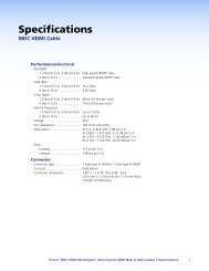
Transmitter Connections <strong>and</strong> Indicators<br />
8<br />
POWER<br />
12V<br />
1.0A MAX<br />
RGB INPUT<br />
<strong>FOXBOX</strong> <strong>Tx</strong> <strong>VGA</strong> Rear Panel<br />
Front Panel<br />
8<br />
2 3 4 5<br />
9<br />
POWER<br />
12V<br />
1.0A MAX<br />
<strong>FOXBOX</strong> <strong>Tx</strong> <strong>DVI</strong> Plus Rear Panel<br />
1<br />
AUDIO<br />
<strong>FOXBOX</strong> <strong>Tx</strong> <strong>VGA</strong><br />
RS-232<br />
OVER FIBER ALARM<br />
<strong>Tx</strong> <strong>Rx</strong> 1 2<br />
<strong>DVI</strong>-D INPUT AUDIO RS-232<br />
OVER FIBER ALARM<br />
<strong>FOXBOX</strong> <strong>Tx</strong> <strong>DVI</strong> Plus<br />
<strong>Tx</strong> <strong>Rx</strong> 1 2<br />
OVER<br />
TEMP<br />
OVER<br />
TEMP<br />
9<br />
RGB<br />
<strong>DVI</strong><br />
AUDIO<br />
AUDIO<br />
Front Panel<br />
Figure 2. <strong>FOXBOX</strong> <strong>Tx</strong> Transmitter Connectors<br />
3<br />
4<br />
5<br />
7<br />
CONFIG<br />
7<br />
CONFIG<br />
<strong>FOXBOX</strong> <strong>Tx</strong> <strong>VGA</strong><br />
<strong>FOXBOX</strong> <strong>Tx</strong> <strong>DVI</strong> Plus<br />
NOTES: • The <strong>FOXBOX</strong> <strong>Tx</strong> <strong>VGA</strong>/<strong>YUV</strong> looks similar to the <strong>FOXBOX</strong> <strong>Tx</strong> <strong>VGA</strong>, with the<br />
exception of the name on the unit <strong>and</strong> the label on the input connector.<br />
• The <strong>FOXBOX</strong> <strong>Tx</strong> <strong>DVI</strong> (non-Plus) looks similar to the <strong>FOXBOX</strong> <strong>Tx</strong> <strong>DVI</strong> Plus, with<br />
the exception of the name on the unit.<br />
a RGB <strong>and</strong> RGB/<strong>YUV</strong> Input connectors<br />
<strong>FOXBOX</strong> <strong>Tx</strong> <strong>VGA</strong> — Connect an analog <strong>VGA</strong>-UXGA RGB video source to this 15-pin<br />
HD female connector.<br />
<strong>FOXBOX</strong> <strong>Tx</strong> <strong>VGA</strong>/<strong>YUV</strong> — Connect bi-level or tri-level sync <strong>YUV</strong> video or an analog<br />
<strong>VGA</strong>-UXGA RGB video source to this 15-pin HD female connector.<br />
b <strong>DVI</strong>-I Input connector (<strong>FOXBOX</strong> <strong>DVI</strong> only) — Connect a single link of <strong>DVI</strong>-D to this<br />
<strong>DVI</strong>-I connector (see “<strong>DVI</strong> connector (<strong>FOXBOX</strong> <strong>DVI</strong>)“ on page 14 for pin assignments).<br />
NOTE: The <strong>FOXBOX</strong> <strong>DVI</strong> accepts only the digital signals on the <strong>DVI</strong>-I Input<br />
connector. The analog pins on the port are not connected.<br />
c Audio connector — Plug an audio input into the transmitter via this stereo mini jack<br />
connector.<br />
NOTE: See figure 3 to identify the tip, ring, <strong>and</strong> sleeve when you are making<br />
connections for the transmitter from existing audio cables. A mono audio<br />
connector consists of the tip <strong>and</strong> sleeve. A stereo audio connector consists<br />
of the tip, ring, <strong>and</strong> sleeve.<br />
Tip (+)<br />
Sleeve ( )<br />
RCA Connector<br />
Tip (+)<br />
Ring (-)<br />
Sleeve ( )<br />
3.5 mm Stereo Plug Connector<br />
(balanced)<br />
Figure 3. Typical Audio Connectors<br />
The input audio level can be set via RS-232 control (see “Remote Control”).<br />
LINK<br />
LINK<br />
<strong>Tx</strong><br />
<strong>Rx</strong><br />
OPTICAL<br />
<strong>Tx</strong><br />
96<br />
96<br />
<strong>Rx</strong><br />
OPTICAL<br />
<strong>FOXBOX</strong> <strong>Tx</strong>/<strong>Rx</strong> • Installation <strong>and</strong> Operation 8<br />
LINK<br />
LINK
d RS-232 Over Fiber port — If you want the <strong>FOXBOX</strong> to pass serial<br />
comm<strong>and</strong> signals to the receiver, for serial control of a projector for example,<br />
RS-232<br />
OVER FIBER ALARM<br />
connect the host device to the transmitter via the first three leftmost poles<br />
(<strong>Tx</strong>, <strong>Rx</strong>, <strong>and</strong> _) of this 5-pole captive screw connector (see “RS-232<br />
connections“ on page 15 to wire this connector).<br />
<strong>Tx</strong> <strong>Rx</strong> 1 2<br />
NOTES: • If you connect only one fiber optic cable (item f, below), or you<br />
configure the receiver for daisy-chaining, you will not receive reports<br />
from the controlled device. To receive responses from the controlled<br />
device, you must install two fiber optic cables <strong>and</strong> leave the <strong>FOXBOX</strong><br />
receiver in normal configuration (Mode DIP switch 1 down on the receiver).<br />
• The <strong>FOXBOX</strong> can pass RS-232 comm<strong>and</strong>s <strong>and</strong> responses at rates up to<br />
115200 baud.<br />
e Alarm outputs port — For remote monitoring of the status of fiber optic<br />
link 2, connect a locally-constructed or furnished monitoring device to the<br />
RS-232<br />
OVER FIBER ALARM<br />
transmitter via the two rightmost poles (1 <strong>and</strong> 2) of this 5-pole captive screw<br />
connector. When the transmitter does not detect a light link on fiber cable<br />
<strong>Tx</strong> <strong>Rx</strong> 1 2<br />
<strong>Rx</strong> (optional), pin 1 <strong>and</strong> pin 2 of this port are shorted together (see “Alarm outputs<br />
connection“ on page 15 to wire this connector).<br />
f Fiber optic connectors <strong>and</strong> LEDs —<br />
WARNING: These units output continuous invisible light, which may be harmful to<br />
the eyes; use with caution. For additional safety, plug the attached dust<br />
caps into the optical transceivers when the fiber cable is unplugged.<br />
NOTES: • Ensure that you use the proper fiber cable for your transmitter/receiver<br />
pair. Typically, singlemode fiber has a yellow jacket <strong>and</strong> multimode cable<br />
has an orange or aqua jacket.<br />
• Only one fiber optic cable, transmitter <strong>Tx</strong> to receiver <strong>Rx</strong>, is required for<br />
video, audio, <strong>and</strong> serial comm<strong>and</strong> transmission. But, if you connect only<br />
one fiber optic cable, or if your transmitter is configured to daisy-chain<br />
the optical signal, system functionality is reduced. You will not receive<br />
RS-232 reports from the controlled device, <strong>and</strong> some FOX Extender<br />
Control Program functions <strong>and</strong> RS-232 comm<strong>and</strong>s will not work. To<br />
receive responses from the controlled device <strong>and</strong> for full functionality, you<br />
need to install both fiber optic cables <strong>and</strong> leave the <strong>FOXBOX</strong> receiver in<br />
normal configuration (Mode DIP switch 1 down on the receiver).<br />
ä <strong>Tx</strong> (required) — For all one-way video, audio, <strong>and</strong> serial<br />
communications from the transmitter to the receiver, connect a<br />
fiber optic cable to the <strong>Tx</strong> LC connector.<br />
Connect the free end of this fiber optic cable to the <strong>Rx</strong> connector<br />
on the <strong>FOXBOX</strong> <strong>Rx</strong> receiver (item o on figure 4) or to any other<br />
compatible <strong>Extron</strong> FOX device.<br />
ã <strong>Rx</strong> (optional) — Connect a fiber optic cable for all one-way return<br />
serial communications from the receiver to the transmitter.<br />
Connect the free end of this fiber optic cable to the <strong>Tx</strong> connector<br />
on a <strong>FOXBOX</strong> <strong>Rx</strong> receiver in normal configuration (item o on<br />
figure 4) or to any other compatible <strong>Extron</strong> FOX device.<br />
<strong>Tx</strong> Link <strong>and</strong> <strong>Rx</strong> Link LEDs — When lit, the link is active (light is<br />
received).<br />
Transmitter<br />
to<br />
LINK<br />
Receiver<br />
LINK<br />
<strong>Tx</strong><br />
OPTICAL<br />
6a 6b<br />
<strong>Tx</strong><br />
<strong>Rx</strong><br />
<strong>Rx</strong><br />
OPTICAL<br />
<strong>FOXBOX</strong> <strong>Tx</strong>/<strong>Rx</strong> • Installation <strong>and</strong> Operation 9<br />
LINK<br />
LINK
g Configuration port — Connect a controlling device, such as a PC, to this port via a<br />
2.5 mm mini jack TRS RS-232 cable for RS-232 protocol control of all <strong>FOXBOX</strong> functions.<br />
See “Front panel Configuration ports“ on page 16 for more details on the adapter<br />
cable <strong>and</strong> “Remote Control“ on page 19 for SIS comm<strong>and</strong>s <strong>and</strong> software control.<br />
The TRS RS-232 cable is included with the <strong>Tx</strong> models.<br />
h DC power connector — Plug the included external 12 VDC power supply into this<br />
connector (see “Power supply wiring“ on page 17, to wire the connector.<br />
i Indicators —<br />
Power LED — This LED lights to indicate that power is applied to the unit.<br />
Over Temp LED — This LED lights to indicate that the unit is operating at a dangerously<br />
high temperature (approximately 167 °F [75 °C]) <strong>and</strong> that equipment damage is<br />
imminent.<br />
RGB (<strong>FOXBOX</strong> <strong>VGA</strong>), RGB/<strong>YUV</strong> (<strong>FOXBOX</strong> <strong>VGA</strong>/<strong>YUV</strong>), or<br />
<strong>DVI</strong> (<strong>FOXBOX</strong> <strong>DVI</strong>) LED — This LED lights when the transmitter detects a signal on its<br />
video input, as follows:<br />
RGB LED — Horizontal sync (H) (for RGBHV video) or Green (Sync on green) (G) (for<br />
RGsB or RsGsBs video)<br />
RGB/<strong>YUV</strong> LED — Horizontal sync (H) (for RGBHV video) or luminance (Y) (for<br />
component video)<br />
<strong>DVI</strong> LED — <strong>DVI</strong> video input<br />
Audio LED — This LED lights when the transmitter detects a low level audio signal for a<br />
short period of time. It goes dark if the audio signal drops below the minimum threshold<br />
for a short period of time.<br />
<strong>FOXBOX</strong> <strong>Tx</strong>/<strong>Rx</strong> • Installation <strong>and</strong> Operation 10
Receiver Connections <strong>and</strong> Indicators<br />
18<br />
<strong>FOXBOX</strong> <strong>Rx</strong> <strong>VGA</strong> Rear Panel<br />
18 16 11<br />
POWER<br />
12V<br />
1.0A MAX<br />
16<br />
POWER MODE<br />
12V<br />
1.0A MAX<br />
MODE<br />
10<br />
RGB OUTPUT<br />
<strong>FOXBOX</strong> <strong>Rx</strong> <strong>DVI</strong> Plus Rear Panel<br />
AUDIO<br />
<strong>FOXBOX</strong> <strong>Rx</strong> <strong>VGA</strong><br />
<strong>DVI</strong>-D OUTPUT AUDIO RS-232<br />
OVER FIBER ALARM<br />
<strong>FOXBOX</strong> <strong>Rx</strong> <strong>DVI</strong> Plus<br />
RS-232<br />
OVER FIBER ALARM<br />
<strong>Tx</strong> <strong>Rx</strong> 1 2<br />
<strong>Tx</strong> <strong>Rx</strong> 1 2<br />
Figure 4. <strong>FOXBOX</strong> <strong>Rx</strong> Receiver Connectors<br />
12<br />
12<br />
13<br />
13<br />
14<br />
14<br />
OVER<br />
TEMP<br />
Front Panel<br />
19<br />
OVER<br />
TEMP<br />
RGB<br />
<strong>DVI</strong><br />
Front Panel<br />
AUDIO<br />
AUDIO<br />
17<br />
CONFIG<br />
17<br />
CONFIG<br />
<strong>FOXBOX</strong> <strong>Rx</strong> <strong>VGA</strong><br />
<strong>FOXBOX</strong> <strong>Rx</strong> <strong>DVI</strong> Plus<br />
j RGB Output connector (<strong>FOXBOX</strong> <strong>Rx</strong> <strong>VGA</strong> only) — Connect an analog <strong>VGA</strong>-UXGA<br />
RGB or <strong>YUV</strong> video display to this 15-pin HD female connector.<br />
NOTE: If the transmitter input is RGB video, you can set the receiver to output the<br />
desired video format: RGBHV or RGsB video.<br />
If the input to a <strong>FOXBOX</strong> <strong>Tx</strong> <strong>VGA</strong>/<strong>YUV</strong> is component video, the output of<br />
the receiver is <strong>YUV</strong> video only. Neither unit can convert the video into the<br />
RGB format.<br />
k <strong>DVI</strong>-I Output connector (<strong>FOXBOX</strong> <strong>DVI</strong> only) — Connect a <strong>DVI</strong> video display to this<br />
<strong>DVI</strong>-I connector (see “<strong>DVI</strong> connector (<strong>FOXBOX</strong> <strong>DVI</strong>)“ on page 14 for pin assignments.<br />
NOTE: The <strong>FOXBOX</strong> <strong>DVI</strong> outputs only the digital signals on the <strong>DVI</strong>-I Output<br />
connector. The analog pins on the port are not connected.<br />
l Audio connector — Plug an audio device into this stereo mini jack connector. See<br />
figure 3 on page 8 for wiring.<br />
RS-232<br />
m RS-232 Over Fiber port — If you want the <strong>FOXBOX</strong> to pass serial OVER FIBER ALARM<br />
comm<strong>and</strong> signals to the receiver, for serial control of a projector for example,<br />
connect the host device to the transmitter via the first three leftmost poles<br />
(<strong>Tx</strong>, <strong>Rx</strong>, <strong>and</strong> _) of this 5-pole captive screw connector (see “RS-232<br />
connections“ on page 15 to wire this connector.<br />
19 9<br />
LINK<br />
LINK<br />
15 9<br />
<strong>Tx</strong><br />
OPTICAL<br />
<strong>Tx</strong><br />
15<br />
<strong>Rx</strong><br />
<strong>Rx</strong><br />
OPTICAL<br />
LINK<br />
LINK<br />
<strong>Tx</strong> <strong>Rx</strong> 1 2<br />
NOTES: • If you connect only one fiber optic cable (item o, on the next page), or<br />
you configure the receiver for daisy-chaining, you will not receive reports<br />
from the controlled device. To receive responses from the controlled<br />
device, you must install two fiber optic cables <strong>and</strong> leave the <strong>FOXBOX</strong><br />
receiver in normal configuration (Mode DIP switch 1 down).<br />
• The <strong>FOXBOX</strong> can pass RS-232 comm<strong>and</strong>s <strong>and</strong> responses at rates up to<br />
115200 baud.<br />
n Alarm outputs port — For remote monitoring of the status of fiber optic<br />
link 1, connect a locally-constructed or furnished monitoring device to the<br />
RS-232<br />
OVER FIBER ALARM<br />
receiver via the two rightmost poles (1 <strong>and</strong> 2) of this 5-pole captive screw<br />
connector. When the receiver does not detect a light link on fiber cable <strong>Tx</strong>,<br />
pin 1 <strong>and</strong> pin 2 of this port are shorted together.<br />
<strong>Tx</strong> <strong>Rx</strong> 1 2<br />
<strong>FOXBOX</strong> <strong>Tx</strong>/<strong>Rx</strong> • Installation <strong>and</strong> Operation 11
o Fiber optic connectors <strong>and</strong> LEDs —<br />
WARNING: These units output continuous invisible light, which may be harmful to<br />
the eyes; use with caution. For additional safety, plug the attached dust<br />
caps into the optical transceivers when the fiber cable is unplugged.<br />
NOTES: • You can connect the transmitter to one or more receivers in one of three<br />
ways:<br />
• One way (transmitter-<strong>Tx</strong>-to-receiver-<strong>Rx</strong>) only — Connect fiber<br />
cable 15a (from transmitter connector ä) only.<br />
From Transmitter<br />
or Daisy-Chained<br />
Receiver<br />
• Two way (transmitter to receiver <strong>and</strong> return) — Connect fiber<br />
cable 15a (from transmitter connector ä) <strong>and</strong> fiber cable 15b back to the<br />
transmitter (connector è). See figure 5.<br />
• One way (transmitter to receiver) with daisy<br />
chain (receiver to receiver) — Connect fiber<br />
cable 15a from a fiber optic source <strong>and</strong> cable 15b <strong>Tx</strong> <strong>Rx</strong><br />
to<br />
the next receiver in the daisy chain. See figure 6.<br />
15b 15a<br />
Set each receiver in the daisy chain to daisy<br />
chain mode (Mode DIP switch 1 up.)<br />
Up to 10 properly-configured receivers can<br />
be connected in a daisy chain to a single<br />
Receiver<br />
transmitter.<br />
• See the transmitter fiber connector NOTES on<br />
page 9, which also apply to these connectors.<br />
15a 15b<br />
15a 15a<br />
Receiver<br />
<strong>Tx</strong> <strong>Rx</strong><br />
15b<br />
Figure 6. Daisy Chain Configuration<br />
<strong>Tx</strong> <strong>Rx</strong><br />
Receiver<br />
Transmitter<br />
( 6a on<br />
<strong>Tx</strong> <strong>Rx</strong><br />
( 6b on<br />
page 9)<br />
page 9)<br />
Figure 5. Two Way<br />
Configuration<br />
15a<br />
<strong>Rx</strong> (required) — For all one-way video, audio, <strong>and</strong> serial communications from the<br />
transmitter to the receiver, connect a fiber optic cable to the <strong>Rx</strong> LC connector.<br />
Connect the free end of this fiber optic cable to the <strong>Tx</strong> connector on the <strong>FOXBOX</strong> <strong>Tx</strong><br />
transmitter (item f on page 9) or to any other compatible <strong>Extron</strong> <strong>FOXBOX</strong> device.<br />
15b<br />
<strong>Tx</strong> (optional) — Connect a fiber optic cable to the <strong>Tx</strong> LC connector for either of<br />
the following functions:<br />
Normal configuration — For all one-way return serial communications from the<br />
receiver to the <strong>Rx</strong> connector on the transmitter. See figure 5.<br />
Daisy chain configuration — For daisy-chained video, audio, <strong>and</strong> serial<br />
communications to the <strong>Rx</strong> connector on another receiver. See figure 6.<br />
NOTE: The <strong>Tx</strong> connector emits light in either case <strong>and</strong> the <strong>Rx</strong> port receives light.<br />
Connect the free end of this fiber optic cable to either:<br />
• The <strong>Rx</strong> connector on the <strong>FOXBOX</strong> <strong>Tx</strong> transmitter (item f on page 9) or to any<br />
other compatible <strong>Extron</strong> FOX device<br />
• The <strong>Rx</strong> connector on another receiver in the daisy chain<br />
<strong>Tx</strong> Link <strong>and</strong> <strong>Rx</strong> Link LEDs — When lit, the link is active (light is received).<br />
<strong>FOXBOX</strong> <strong>Tx</strong>/<strong>Rx</strong> • Installation <strong>and</strong> Operation 12
p Mode switch —<br />
DIP switch 1 — To connect the received optical input to another receiver in a daisy<br />
chain configuration, set DIP switch 1 to up as shown. Up to 10 properly-configured<br />
receivers can be connected in a daisy chain to a single transmitter.<br />
DIP Switch 2 — DIP switch 2 must be set to the up position for the receiver to respond<br />
properly to the Video Shutdown Delay SIS comm<strong>and</strong>.<br />
q Configuration port — Connect a controlling device, such as a PC, to this port via a<br />
2.5 mm mini jack TRS RS-232 cable for RS-232 protocol control of all <strong>FOXBOX</strong> functions.<br />
See “Front panel Configuration ports“ on page 16 for more details on the adapter<br />
cable <strong>and</strong> “Remote Control“ on page 19 for SIS comm<strong>and</strong>s <strong>and</strong> software control.<br />
The TRS RS-232 cable is included with the <strong>Tx</strong> models.<br />
r DC power connector — Plug the included external 12 VDC power supply into this<br />
connector (see “Power supply wiring“ on page 17 to wire the connector.<br />
s Indicators —<br />
Power LED — This LED lights to indicate that power is applied to the unit.<br />
Over Temp LED — This LED lights to indicate that the unit is operating at a dangerously<br />
high temperature (approximately 167 °F [75 °C]) <strong>and</strong> that equipment damage is<br />
imminent.<br />
RGB (<strong>FOXBOX</strong> <strong>VGA</strong>) or <strong>DVI</strong> (<strong>FOXBOX</strong> <strong>DVI</strong>) LED — This LED lights on the receiver<br />
when the transmitter detects a signal on its video input, as follows:<br />
RGB LED — Horizontal sync (H) (for RGBHV video) or Green (Sync on green) (G) (for<br />
RGsB or RsGsBs video)<br />
RGB/<strong>YUV</strong> LED — Horizontal sync (H) (for RGBHV video) or luminance (Y) (for<br />
component video)<br />
<strong>DVI</strong> LED — <strong>DVI</strong> video input<br />
Audio LED — This LED lights on the receiver when the transmitter detects a low level<br />
audio signal for a short period of time. It goes dark if the audio signal drops below the<br />
minimum threshold for a short period of time.<br />
MODE<br />
<strong>FOXBOX</strong> <strong>Tx</strong>/<strong>Rx</strong> • Installation <strong>and</strong> Operation 13<br />
1 2
Making Connections<br />
9<br />
<strong>DVI</strong> connector (<strong>FOXBOX</strong> <strong>DVI</strong>)<br />
Figure 7 defines the <strong>DVI</strong> pin assignments.<br />
1<br />
C5<br />
17 24 C3 C4<br />
Female Connector<br />
8<br />
Male Connector<br />
C1 C2<br />
Figure 7. <strong>DVI</strong> Connectors<br />
Pin Signal<br />
Pin Signal Pin Signal<br />
1 TMDS data 2– 9 TMDS data 1– 17 TMDS data 0–<br />
2 TMDS data 2+ 10 TMDS data 1+ 18 TMDS data 0+<br />
3 TMDS data 2 shield 11 TMDS data 1shield 19TMDS<br />
data 0 shield<br />
4 Spare 12 Spare 20Spare<br />
5 Spare 13 Spare 21Spare<br />
6 DDC clock 14 +5 V power 22<br />
7 DDC data 15 Ground (+5 V) 23TMDS<br />
clock+<br />
8 No connection 16 Hot Plug Detect 24TMDS<br />
clock–<br />
C1 Analog Red Video C3 Analog Blue Video C5 Analog Ground<br />
C2 Analog Green Video C4 Analog H. Sync<br />
NOTE: The missing pins on the included <strong>DVI</strong> cable are not required for the single link<br />
of <strong>DVI</strong>-D data supported by the <strong>FOXBOX</strong> <strong>DVI</strong>. The analog video pins are not<br />
connected. All of these unused pins are shaded gray in the figure above.<br />
<strong>DVI</strong> signals run at a very high frequency <strong>and</strong> are especially prone to errors caused by bad<br />
video connections, too many adapters, or excessive cable length. To avoid the loss of an<br />
image or jitter, follow these guidelines:<br />
• Do not exceed 16.4 feet (5 meters) on the input or buffered loop-through of the<br />
<strong>FOXBOX</strong> <strong>DVI</strong> transmitter or the output of the <strong>FOXBOX</strong> <strong>DVI</strong> receiver.<br />
• Use only the cable designed for <strong>DVI</strong> signals that is supplied by <strong>Extron</strong>.<br />
• Limit or avoid the use of adapters.<br />
• Use only cables specifically intended for <strong>DVI</strong> or HDMI signals. Use of non-<strong>DVI</strong> or non-<br />
HDMI cables or modified cables can result in a missing video output.<br />
<strong>FOXBOX</strong> <strong>Tx</strong>/<strong>Rx</strong> • Installation <strong>and</strong> Operation 14
RS-232 connections<br />
The RS-232 Over Fiber port is for transmission of serial signals, such as projector control<br />
signals, between the transmitter <strong>and</strong> receiver.<br />
RS-232<br />
OVER FIBER<br />
ALARM<br />
<strong>Tx</strong> <strong>Rx</strong> 1 2<br />
Do not tin the wires!<br />
Ground ( )<br />
Receive (<strong>Rx</strong>)<br />
Transmit (<strong>Tx</strong>)<br />
Pin Function<br />
TX Transmit data<br />
RX Receive data<br />
Gnd Signal ground<br />
Bidirectional<br />
Controlling<br />
Device<br />
Ground ( )<br />
Receive (<strong>Rx</strong>)<br />
Transmit (<strong>Tx</strong>)<br />
NOTE Cross the <strong>Tx</strong> <strong>and</strong> <strong>Rx</strong> lines once between the source<br />
<strong>and</strong> the target.<br />
Figure 8. RS-232 Over Fiber Connector<br />
CAUTION: The length of the exposed (stripped) copper wires is important. The ideal<br />
length is 3/16 inch (5 mm).<br />
• Longer bare wires can short together.<br />
• Shorter wires are not as secure in the connectors <strong>and</strong> could be pulled<br />
out.<br />
Alarm outputs connection<br />
RS-232<br />
OVER FIBER<br />
ALARM<br />
<strong>Tx</strong> <strong>Rx</strong> 1 2<br />
Pin 1 <strong>and</strong> pin 2 are<br />
shorted together when<br />
no light is detected.<br />
Do not tin the wires!<br />
Figure 9. Alarm Connector<br />
CAUTION: The length of the exposed (stripped) copper wires is important (see Above).<br />
<strong>FOXBOX</strong> <strong>Tx</strong>/<strong>Rx</strong> • Installation <strong>and</strong> Operation 15
Front panel Configuration ports<br />
NOTE: These ports are for remote control of the transmitter or receiver, not for the over<br />
fiber RS-232 link.<br />
The Configuration ports on the transmitter <strong>and</strong> receiver are 2.5 mm mini stereo jacks. The<br />
9-pin D to 2.5 mm mini jack TRS RS-232 cable, part #70-335-01 (figure 10), included with<br />
transmitters, can be used for this connection.<br />
1<br />
5<br />
6<br />
9<br />
6 feet<br />
(1.8 m)<br />
Part #70-335-01<br />
9-pin D Connection TRS Plug<br />
Pin 2 Computer's RX line Tip<br />
Pin 3 Computer's TX line Ring<br />
Pin 5 Computer's signal ground Sleeve<br />
Figure 10. 9-pin TRS RS-232 Cable<br />
Tip<br />
Ring<br />
Sleeve (Gnd)<br />
This port is RS-232 only, with the following protocols:<br />
• 9600 baud • no parity • 8 data bits<br />
• 1 stop bit • no flow control<br />
NOTE: The maximum distances from the transmitter or receiver to the controlling<br />
device can vary up to 200 feet (61 m). Factors such as cable gauge, baud rates,<br />
environment, <strong>and</strong> output levels (from the unit <strong>and</strong> the controlling device) all<br />
affect transmission distance. Distances of about 50 feet (15 m) are typically not<br />
a problem. In some cases, the unit may be capable of serial communications via<br />
RS-232 up to 250 feet (76 m) away.<br />
See “Remote Control“ for definitions of the SIS comm<strong>and</strong>s (serial comm<strong>and</strong>s to control the<br />
transmitter via this connector) <strong>and</strong> software control.<br />
<strong>FOXBOX</strong> <strong>Tx</strong>/<strong>Rx</strong> • Installation <strong>and</strong> Operation 16
Power supply wiring<br />
CAUTION: Always use power supplies specified by <strong>Extron</strong> for the <strong>FOXBOX</strong> units.<br />
Use of an unauthorized power supply voids all regulatory compliance<br />
certification <strong>and</strong> may cause damage to the supply <strong>and</strong> the unit.<br />
Figure 11 shows how to wire the power connector.<br />
Smooth<br />
Ridges<br />
Power Supply<br />
Output Cord<br />
A A<br />
SECTION A–A<br />
Tie Wrap<br />
Figure 11. Power Connector Wiring<br />
Captive Screw<br />
Connector<br />
CAUTIONS: This product is intended to be supplied by a Listed Power Unit marked<br />
“Class 2” or “LPS,” rated 12 VDC, 1.0 A minimum. Always use power<br />
supplies supplied by or specified by <strong>Extron</strong>. Use of an unauthorized power<br />
supply voids all regulatory compliance certification <strong>and</strong> may cause damage<br />
to the supply <strong>and</strong> the end product.<br />
Unless otherwise stated, the AC/DC adapters are not suitable for use in<br />
air h<strong>and</strong>ling spaces or in wall cavities. The installation must always be in<br />
accordance with the applicable provisions of National Electrical Code ANSI/<br />
NFPA 70, article 75 <strong>and</strong> the Canadian Electrical Code part 1, section 16.<br />
The power supply shall not be permanently fixed to a building structure or<br />
similar structure.<br />
Power supply voltage polarity is critical. Incorrect voltage polarity can<br />
damage the power supply <strong>and</strong> the unit. The ridges on the side of the cord<br />
(figure 11) identify the power cord negative lead.<br />
To verify the polarity before connection, plug in the power supply with no load <strong>and</strong> check<br />
the output with a voltmeter.<br />
WARNING: The two power cord wires must be kept separate while the power supply is<br />
plugged in. Remove power before wiring.<br />
CAUTION: The length of the exposed (stripped) copper wires is important. The<br />
ideal length is 3/16 inch (5 mm). See the RS-232 Over Fiber connector<br />
CAUTION for more information.<br />
NOTE: Do not tin the power supply leads before installing them in the captive screw<br />
connector. Tinned wires are not as secure in the connectors <strong>and</strong> could be pulled<br />
out.<br />
Use the supplied tie wrap to strap the power cord to the extended tail of the connector.<br />
3 5<br />
<strong>FOXBOX</strong> <strong>Tx</strong>/<strong>Rx</strong> • Installation <strong>and</strong> Operation 17
Operation<br />
Alternatively, an optional <strong>Extron</strong> PS 124 Universal 12 VDC Power Supply, part #60-1022-01,<br />
can power multiple <strong>Extron</strong> 12 VDC devices using only one AC power connector.<br />
After the transmitter, all receivers, <strong>and</strong> their connected devices are powered up, the system<br />
is fully operational. If any problems are encountered, verify that the cables are routed <strong>and</strong><br />
connected properly, <strong>and</strong> that all display devices have identical resolutions <strong>and</strong> refresh rates.<br />
If your problems persist, call the <strong>Extron</strong> S3 Sales & Technical Support Hotline. See the contact<br />
numbers on the last page of this guide for the <strong>Extron</strong> office nearest you.<br />
To take advantage of the various adjustments <strong>and</strong> test patterns available in the <strong>FOXBOX</strong>,<br />
you need to connect a computer or other RS-232 capable device to the front panel<br />
Configuration port on either unit <strong>and</strong> operate using either SIS comm<strong>and</strong>s or the FOX<br />
Extenders Control Program (see “Remote Control”).<br />
<strong>FOXBOX</strong> <strong>Tx</strong>/<strong>Rx</strong> • Installation <strong>and</strong> Operation 18
Remote Control<br />
This section describes the remote control operation of the <strong>FOXBOX</strong> <strong>VGA</strong>,<br />
<strong>FOXBOX</strong> <strong>VGA</strong>/<strong>YUV</strong>, <strong>FOXBOX</strong> <strong>DVI</strong> Plus, <strong>and</strong> <strong>FOXBOX</strong> <strong>DVI</strong>, including:<br />
• Simple Instruction Set Control<br />
• FOX Extenders Control Program<br />
The transmitter <strong>and</strong> receiver each have a Configuration port, a 2.5 mm mini stereo jack<br />
that can be connected to a host device such as a computer running the HyperTerminal<br />
utility, an RS-232 capable PDA, or a control system. These ports make serial control of the<br />
transmitter <strong>and</strong> receiver possible.<br />
The <strong>Extron</strong> 9-pin D to 2.5 mm mini jack TRS RS-232 cable, included with the transmitter,<br />
but available separately, part #70-335-01 (figure 12) can be used for connection to the<br />
Configuration port.<br />
1<br />
5<br />
6<br />
9<br />
6 feet<br />
(1.8 m)<br />
Part #70-335-01<br />
9-pin D Connection TRS Plug<br />
Pin 2 Computer's RX line Tip<br />
Pin 3 Computer's TX line Ring<br />
Pin 5 Computer's signal ground Sleeve<br />
Figure 12. 9-pin TRS RS-232 Cable<br />
Tip<br />
Ring<br />
Sleeve (Gnd)<br />
The protocol for the ports is as follows:<br />
• 9600 baud • no parity • 8 data bits<br />
• 1 stop bit • no flow control<br />
NOTES: Only one fiber optic cable, transmitter-<strong>Tx</strong>-to-receiver-<strong>Rx</strong>, is required for<br />
video, audio, <strong>and</strong> serial comm<strong>and</strong> transmission. But, if you connect only one<br />
fiber optic cable, you will not receive RS-232 reports from the controlled<br />
device, <strong>and</strong> there will be reduced RS-232 comm<strong>and</strong> <strong>and</strong> control program<br />
functionality on the <strong>Rx</strong> unit. To receive responses from the controlled device<br />
<strong>and</strong> for full functionality, install both fiber optic cables <strong>and</strong> leave the <strong>FOXBOX</strong><br />
receiver in normal configuration (Mode DIP switch 1 down on the receiver).<br />
<strong>FOXBOX</strong> <strong>Tx</strong>/<strong>Rx</strong> • Remote Control 19
Simple Instruction Set Control<br />
Host-to-Unit Instructions<br />
SIS comm<strong>and</strong>s consist of one or more characters per field. No special characters are required<br />
to begin or end a comm<strong>and</strong> character sequence. When a comm<strong>and</strong> is valid, the unit<br />
executes the comm<strong>and</strong> <strong>and</strong> sends a response to the host device. All responses from the unit<br />
to the host end with a carriage return <strong>and</strong> a line feed (CR/LF = ]), which signals the end of<br />
the response character string. A string is one or more characters.<br />
Symbol Definitions<br />
] = CR/LF (carriage return/line feed)<br />
} = Carriage return (no line feed)<br />
• = Space (hard) character<br />
E = Escape key (hex 1B)<br />
X! = Mute/auto memory status 0 = off 1 = on<br />
X@ = Resolution 01 = 1920 x 1200 11 = 576p<br />
02 = 800 x 600 12 = 720p<br />
03 = 1024 x 768 13 = 1080i<br />
04 = 1280 x 768 14 = 1080p<br />
05 = 1280 x 1024 15 = 640 x 480<br />
06 = 1365 x 768 16 = 1440 x 900<br />
07 = 1366 x 768 17 = 1280 x 800<br />
08 = 1400 x 1050 18 = 1680 x 1050<br />
09 = 1600 x 1200 19 = 1360 x 768<br />
10 = 480p<br />
X# = Refresh rate 1 = 50 Hz 2 = 60 Hz<br />
X$ = Mode switch position 0 = off (down) 1 = on (up)<br />
X% = Output sync format 0 = RGBHV 1 = RGsB<br />
X^ = Output sync polarity 0 = follows input 1 = force sync negative<br />
X& = Horizontal <strong>and</strong> vertical position 000 through 255<br />
X* = Horizontal start 000 through 255<br />
X( = Pixel phase 00 through 31<br />
X1) = Total pixels ± 255 of default value for selected resolution<br />
X1! = Sync frequency xxx.xx (frequency in kHz [H] or Hz [V])<br />
X1@ = Memory preset number 01 to 30<br />
X1# = Audio gain adjustment range 00 to 10<br />
X1$ = Audio level adjustment range<br />
–18 to +10 (in 1.0 dB steps)<br />
X1% = Audio attenuation adjustment range 00 to 18<br />
X1^ = Audio output level 0 = consumer (–10 dBV) 1 = professional (+4 dBu)<br />
X1& = Test pattern 0 = none 2 = grayscale<br />
1 = color bars 3 = alternating pixels<br />
X1* = Video shutdown interval 0 = 0 seconds (off) 4 = 1 second<br />
1 = 0.25 second 5 = 1.25 second<br />
2 = 0.5 second (default)<br />
3 = 0.75 second<br />
6 = 1.5 second<br />
X1( = <strong>Rx</strong> link enable 0 = disable 1 = enable (default)<br />
X2) = Link <strong>and</strong> input status 0 = link or input not sensed 1 link or input sensed<br />
X2! = Transmission mode SM = singlemode MM = multimode<br />
X2@ = Transmitter or receiver <strong>Tx</strong> = transmitter <strong>Rx</strong> = receiver<br />
X2# = Firmware version v.vv<br />
X2$ = Internal temperature nnnF•nnC<br />
<strong>FOXBOX</strong> <strong>Tx</strong>/<strong>Rx</strong> • Remote Control 20
Unit-initiated Messages<br />
When a local event, such as an equipment power-up, occurs, the unit responds by sending a<br />
message to the host. The unit-initiated messages are listed below:<br />
(c) Copyright 2010, <strong>Extron</strong> <strong>Electronics</strong> <strong>FOXBOX</strong> <strong>Tx</strong> <strong>VGA</strong>, Vx.xx, 60-934-xx]]<br />
- or -<br />
(c) Copyright 2010, <strong>Extron</strong> <strong>Electronics</strong> <strong>FOXBOX</strong> <strong>Rx</strong> <strong>VGA</strong>, Vx.xx, 60-934-xx]]<br />
- or -<br />
(c) Copyright 2010, <strong>Extron</strong> <strong>Electronics</strong> <strong>FOXBOX</strong> <strong>Tx</strong> <strong>VGA</strong>/<strong>YUV</strong>, Vx.xx, 60-1058-xx]]<br />
- or -<br />
(c) Copyright 2010, <strong>Extron</strong> <strong>Electronics</strong> <strong>FOXBOX</strong> <strong>Tx</strong> <strong>DVI</strong>, Vx.xx, 60-935-xx]]<br />
- or -<br />
(c) Copyright 2010, <strong>Extron</strong> <strong>Electronics</strong> <strong>FOXBOX</strong> <strong>Rx</strong> <strong>DVI</strong>, Vx.xx, 60-935-xx]]<br />
- or -<br />
(c) Copyright 2010, <strong>Extron</strong> <strong>Electronics</strong> <strong>FOXBOX</strong> <strong>Tx</strong> <strong>DVI</strong> Plus, Vx.xx, 60-1060-xx]]<br />
- or -<br />
(c) Copyright 2010, <strong>Extron</strong> <strong>Electronics</strong> <strong>FOXBOX</strong> <strong>Rx</strong> <strong>DVI</strong> Plus, Vx.xx, 60-1060-xx]]<br />
The connected unit issues the appropriate copyright message (above) when it first powers<br />
on. Vx.xx is the firmware version number; 60-xxxx-xx is the part number of the connected<br />
unit.<br />
Reconfig]<br />
The unit sends the Reconfig message whenever the video input signal to the transmitter is<br />
changed.<br />
1LnkX2)•2LnkX2)•RGBX2)•AudX2)]<br />
The unit sends the status message whenever a change in the fiber link <strong>and</strong> video <strong>and</strong> audio<br />
connection occurs.<br />
DipX$X$]<br />
The unit sends the DIP switch position message whenever a change in the DIP switch<br />
settings occurs on the receiver.<br />
<strong>FOXBOX</strong> <strong>Tx</strong>/<strong>Rx</strong> • Remote Control 21
Error Responses<br />
When the unit receives a valid SIS comm<strong>and</strong>, it executes the comm<strong>and</strong> <strong>and</strong> sends a response<br />
to the host device. If the unit is unable to execute the comm<strong>and</strong> because the comm<strong>and</strong> is<br />
invalid or it contains invalid parameters, the unit returns an error response to the host. The<br />
error response codes are:<br />
E10 - Invalid comm<strong>and</strong><br />
E11 - Invalid preset number<br />
E13 - Invalid parameter<br />
E14 - Invalid comm<strong>and</strong> for this configuration<br />
Using the Comm<strong>and</strong>/Response Tables<br />
The comm<strong>and</strong>/response table begins on the next page. Either uppercase or lower case letters<br />
are acceptable in the comm<strong>and</strong> field except where indicated for the audio level (gain <strong>and</strong><br />
attenuation) comm<strong>and</strong>s. Symbols are used throughout the table to represent variables in<br />
the comm<strong>and</strong>/response fields. Comm<strong>and</strong> <strong>and</strong> response examples are shown throughout the<br />
table. The ASCII to HEX conversion table below is for use with the comm<strong>and</strong>/response table.<br />
Space<br />
ASCII to Hex Conversion Table<br />
•<br />
<strong>FOXBOX</strong> <strong>Tx</strong>/<strong>Rx</strong> • Remote Control 22
Comm<strong>and</strong>/Response Table for SIS Comm<strong>and</strong>s<br />
Comm<strong>and</strong> ASCII Comm<strong>and</strong><br />
(host to unit)<br />
Response<br />
(unit to host)<br />
Additional description<br />
Video mute<br />
Mute output 1B Blk1] Blank the video output.<br />
Unmute output 0B Blk0] Output video.<br />
Show video mute status B X!] Video mute status is X!.<br />
Display Data Channel (DDC) resolution <strong>and</strong> rate (systems with <strong>DVI</strong> receivers only)<br />
NOTE: If the receiver is a FOX 500, the rear panel DDC Resol(ution) rotary switch on the transmitter must be in position 1 for the<br />
variables to be changeable via an SIS comm<strong>and</strong>. The unit returns the E14 error if the switch is in other than position 1.<br />
Set DDC resolution 41*X@*X## DDCX@*X#] Select a DDC Resolution.<br />
Show DDC resolution 41# X@*X#] Show the DDC resolution.<br />
Mode switch position (systems with <strong>FOXBOX</strong> receivers only)<br />
Show DIP switch position 8# X$X$] Show the <strong>FOXBOX</strong> receiver DIP switch position.<br />
Output sync format<br />
Set output sync format 6*X%# SynX%] Set the sync format.<br />
Show output sync format<br />
Output sync polarity<br />
6# X%]<br />
Set output polarity<br />
negative<br />
7*1# Pol1] Force the receiver output to always be negative.<br />
Set polarity to the input 7*0# Pol0] Polarity follows the video sync input to the transmitter.<br />
Show output sync polarity<br />
Horizontal shift<br />
7# X^]<br />
Set a horizontal position X&H HphX&] Set horizontal centering to X&.<br />
Increment position +H HphX&] Shift the image one pixel to the right.<br />
Decrement position –H HphX&] Shift the image one pixel to the left.<br />
Show position<br />
Vertical shift<br />
H X&]<br />
Set a vertical position X&/ VphX&] Set vertical centering to X&.<br />
Increment position +/ VphX&] Shift the image down one line.<br />
Decrement position –/ VphX&] Shift the image up one line.<br />
Show position<br />
Horizontal start<br />
/ X&]<br />
NOTE: When the controlling PC is connected to the receiver, the <strong>FOXBOX</strong> can perform this comm<strong>and</strong> only if the receiver-<strong>Tx</strong>-totransmitter-<strong>Rx</strong><br />
fiber cable is connected. The unit returns the E14 error if the <strong>Rx</strong> fiber is not connected.<br />
Set a start position X*) HstX*] Set the horizontal location of the first active pixel.<br />
Example: 128) Hst128] Set pixel 128 as the first active pixel.<br />
Increment start position +) HstX*] Increase the horizontal start location value.<br />
Decrement start position –) HstX*] Decrease the horizontal start location value.<br />
Show start position ) X*]<br />
NOTE: X! = Mute status 0 = off 1 = on<br />
X@ = Resolution 01 through 19. See page 20.<br />
X# = Refresh rate 1 = 50 Hz 2 = 60 Hz<br />
X$ = Mode switch position 0 = off (down) 1 = on (up)<br />
X% = Output sync format 0 = RGBHV 1 = RGsB<br />
X^ = Output sync polarity 0 = follows input 1 = force sync negative<br />
X& = Horizontal <strong>and</strong> vertical position 000 through 255<br />
X* = Horizontal start 000 through 255<br />
<strong>FOXBOX</strong> <strong>Tx</strong>/<strong>Rx</strong> • Remote Control 23
Comm<strong>and</strong>/response table for SIS comm<strong>and</strong>s (continued)<br />
Comm<strong>and</strong> ASCII Comm<strong>and</strong><br />
(host to unit)<br />
Pixel phase<br />
Response<br />
(unit to host)<br />
Additional description<br />
NOTE: When the controlling PC is connected to the receiver, the <strong>FOXBOX</strong> can perform this comm<strong>and</strong> only if the receiver-<strong>Tx</strong>-totransmitter-<strong>Rx</strong><br />
fiber cable is connected. The unit returns the E14 error if the <strong>Rx</strong> fiber is not connected.<br />
Set a pixel phase value X(U PhsX(] Set the pixel phase value to X(.<br />
Example: 10U Phs10] Set the pixel phase value to 10.<br />
Increment pixel phase +U PhsX(] Increase pixel phase value by 1.<br />
Decrement pixel phase –U PhsX(] Decrease pixel phase value by 1.<br />
Show pixel phase U X(]<br />
Total pixels<br />
NOTE: When the controlling PC is connected to the receiver, the <strong>FOXBOX</strong> can perform this comm<strong>and</strong> only if the receiver-<strong>Tx</strong>-totransmitter-<strong>Rx</strong><br />
fiber cable is connected. The unit returns the E14 error if the <strong>Rx</strong> fiber is not connected.<br />
Set a total pixel value 11*X1)# TpxX1)] Set the total pixels to a specific value.<br />
Example: 11*1555# Tpx1555] Set the total pixel value to 1555.<br />
Increment total pixel value +11# TpxX1)] Increase total pixels by 1 pixel.<br />
Decrement total pixel<br />
value<br />
–11# TpxX1)] Decrease total pixels by 1 pixel.<br />
Show total pixel value 11# TpxX1)]<br />
List sync frequency<br />
View input frequency 1LS X1! horozontal ,X1! vertical]<br />
Memory presets<br />
List the input frequency.<br />
Save preset X1@, SprX1@] Comm<strong>and</strong> code is a comma.<br />
Recall preset X1@. RprX1@] Comm<strong>and</strong> code is a period.<br />
Audio input gain <strong>and</strong> attenuation<br />
NOTES: • The set gain (G) <strong>and</strong> set attenuation (g) comm<strong>and</strong>s are case sensitive. The increment level, decrement level, <strong>and</strong> show level are<br />
not case sensitive.<br />
• When the controlling PC is connected to the receiver, the <strong>FOXBOX</strong> can perform this comm<strong>and</strong> only if the receiver-<strong>Tx</strong>-totransmitter-<strong>Rx</strong><br />
fiber cable is connected. The unit returns the E14 error if the <strong>Rx</strong> fiber is not connected.<br />
Set input audio gain to a<br />
+dB value<br />
X1#G AudX1$] Set the input level (gain) to +X1# dB.<br />
Example: 2G Aud+02] Set the input level (gain) to +2 dB.<br />
Set input audio<br />
attenuation to a -dB value<br />
X1%g AudX1$] Set the input level (attenuation) to –X1# dB.<br />
Increment input level +G AudX1$] Increase the audio level by 1 dB.<br />
Example: +G Aud+03] Increment the input level from +2 dB to +3 dB.<br />
Decrement input level –G Aud–01] Decrease the audio level from 0 dB to –1 dB.<br />
Show input level<br />
Audio output level<br />
G X1$]<br />
NOTE: The <strong>FOXBOX</strong> receiver outputs audio at the consumer level (-10 dBV) only. The FOX 500 or PowerCage FOX can be configured to<br />
output audio at the professional level; refer to the applicable User Guide.<br />
Set the output to the 40*0# Lvl0] Set the audio output to the consumer level<br />
consumer level<br />
(–10 dBV).<br />
Set the output to the 40*1 Lvl1] Set the audio output to the professional level<br />
professional level<br />
(+4 dBu).<br />
Show output level 40# X1^] Show the audio output level.<br />
NOTE: X( = Pixel phase 00 to 31<br />
X1) = Total pixels ± 255 of default value for selected resolution<br />
X1! = Sync frequency xxx.xx (frequency in kHz [H] or Hz [V]<br />
X1@ = Memory preset number 01 to 30<br />
X1# = Audio gain adjustment range 00 to 10<br />
X1$ = Audio level adjustment range -18 to +10 (in 1.0 dB steps)<br />
X1% = Audio attenuation adjustment range 00 to 18<br />
X1^ = Audio output level 0 = consumer (–10 dBV) 1 = professional (+4 dBu)<br />
<strong>FOXBOX</strong> <strong>Tx</strong>/<strong>Rx</strong> • Remote Control 24
Comm<strong>and</strong>/response table for SIS comm<strong>and</strong>s (continued)<br />
Comm<strong>and</strong> ASCII Comm<strong>and</strong><br />
(host to unit)<br />
Response<br />
(unit to host)<br />
Additional description<br />
Audio mute<br />
Mute the audio 1Z Amt1] Silence the audio output of the receiver.<br />
Unmute the audio 0Z Amt0] The receiver outputs audio.<br />
Show audio mute statue Z X!] Audio mute status is X!.<br />
Auto memory<br />
Disable auto memory 55*0# Img0]<br />
Enable auto memory 55*1# Img1]<br />
Show auto memory status 55# X!]<br />
Auto Image<br />
Trigger Auto Image 55*2# Img]<br />
Test pattern<br />
NOTE: You must have a video input connected <strong>and</strong> the transmitter-<strong>Tx</strong>-to-receiver-<strong>Rx</strong> fiber cable connected for the receiver to output a<br />
selected test pattern. The test pattern turns off if the input signal rate changes or is disconnected or if power is removed.<br />
Output color bars 1J Tst1] Set the receiver to output the color bars test pattern.<br />
Output grayscale 2J Tst2] Set the receiver to output the grayscale test pattern.<br />
Output alternating pixels 3J Tst3] Set the receiver to output the alternating pixels test<br />
pattern.<br />
Turn test pattern off 0J Tst4] Set the receiver to output the input video (no test<br />
pattern is selected).<br />
Show test pattern status J X1&]<br />
Disable <strong>and</strong> enable return link<br />
NOTE: The disable return link function is primarily used <strong>and</strong> recommended when the transmitting device is a FOX 500 DA6 <strong>and</strong> the<br />
receiver is connect to any of outputs 2 through 6 on the DA.<br />
Disable return link 66*0*0# Rle*0*0] Disable link 2.<br />
Enable return link to<br />
transmitter<br />
66*0*1# Rle*0*1] Enable link 2 (default setting).<br />
Show return link status<br />
Video shutdown delay<br />
66*0# 0*X1^]<br />
NOTES: • This comm<strong>and</strong> mutes the output for a variable period of time when the unit detects a change in the input pixel clock.<br />
0.5 second is the default. This feature can prevent glitches when the input video signal resolution changes.<br />
• Front panel DIP switch 2 must be on (up) for this comm<strong>and</strong> to function.<br />
Enable video shutdown 3*X1*# DlyX1*] Mute the output for an interval of X1*.<br />
Example: 3*3# Dly3] Mute the output for 0.75 second.<br />
View video shutdown 3# X1*] The video shutdown interval is X1*.<br />
NOTE: X! = Mute <strong>and</strong> auto memory status 0 = off 1 = on<br />
X1& = Test pattern 0 = none 2 = grayscale<br />
1 = color bars 3 = alternating pixels<br />
X1( = <strong>Rx</strong> link 0 = disable 1 = return link enable<br />
X1* = Video shutdown interval 0 = 0 sec. (off) 2 = 0.5 sec. 4 = 1 sec. 6 = 1.5 sec.<br />
1 = 0.25 sec. 3 = 0.75 sec. 5 = 1.25 sec.<br />
<strong>FOXBOX</strong> <strong>Tx</strong>/<strong>Rx</strong> • Remote Control 25
Comm<strong>and</strong>/response table for SIS comm<strong>and</strong>s (continued)<br />
Comm<strong>and</strong> ASCII Comm<strong>and</strong><br />
(host to unit)<br />
Response<br />
(unit to host)<br />
NOTE: X2) = Link or input status 0 = light or signal input not detected<br />
1 = light or signal detected<br />
X2! = Transmission mode SM = singlemode MM = multimode<br />
X2@ = Transmitter or receiver <strong>Tx</strong> = transmitter <strong>Rx</strong> = receiver<br />
X2# = Firmware version v.vv<br />
X2$ = Internal temperature nnnF•nnC<br />
Additional description<br />
Information requests<br />
Information request I 1LnkX2)•2LnkX2)•RGBX2)•AudX2)•X2!•X2@]<br />
The unit responds with the current status (signal<br />
detected) of optical link 1, optical link 2, the<br />
video input, <strong>and</strong> the audio link; the fiber optic<br />
transmission mode (singlemode or multimode); <strong>and</strong><br />
the device type (<strong>Tx</strong> or <strong>Rx</strong>).<br />
NOTE: The receiver monitors the primary (transmitter-TX to receiver-<strong>Rx</strong>) fiber cable. If the PC is connected to the transmitter <strong>and</strong> the<br />
receiver-<strong>Tx</strong>-to-transmitter-<strong>Rx</strong> fiber cable is not connected, for the I <strong>and</strong> 1S comm<strong>and</strong>s, the transmitter reports 1link0 regardless<br />
of the status of the primary cable.<br />
Show firmware version Q X2#]<br />
Example: Q 1.23] The factory-installed firmware version is 1.23<br />
(sample value only).<br />
Request part number N 60-nnn-nn] See “Part Numbers.”<br />
Request part number of<br />
other unit<br />
1N 60-nnn-nn] See “Part Numbers.”<br />
Show link 1 status 1S X2)] Light status on transmitter-<strong>Tx</strong>-to-receiver-<strong>Rx</strong> cable.<br />
Show link 2 status 2S X2)] Light status on receiver-<strong>Tx</strong>-to-transmitter-<strong>Rx</strong> cable.<br />
Show input video status 3S X2)] Show transmitter video input status.<br />
Show input audio status 4S X2)] Show transmitter audio input status.<br />
Show temperature<br />
Resets<br />
20S X2$] Show temperature in degrees Fahrenheit <strong>and</strong> Celsius.<br />
Reset audio EZA} Zpa] Reset audio setting to default levels (0 dB gain).<br />
Reset memory presets EZG} Zpg] Reset (erase) all memory presets.<br />
System reset EZXXX} Zpx] Reset all settings to factory defaults.<br />
<strong>FOXBOX</strong> <strong>Tx</strong>/<strong>Rx</strong> • Remote Control 26
FOX Extenders Control Program<br />
The <strong>Extron</strong> FOX Extenders Control Program, which communicates with the transmitter <strong>and</strong><br />
receiver pair via the Remote RS-232 port of either unit provides an easy way to operate the<br />
pair.<br />
The program is compatible with Windows 2000, Windows XP, or later. Updates to this<br />
program can be downloaded from the <strong>Extron</strong> website (www.extron.com).<br />
Installing the Software<br />
The program is contained on a DVD. To install the software, insert the DVD into the drive.<br />
The <strong>Extron</strong> software DVD window should appear automatically. If it does not self-start, run<br />
Launch.exe from the DVD. Click the Software tab, scroll to the desired program, <strong>and</strong> click<br />
Install. Follow the instructions that appear on the screen. By default, the installation<br />
creates a C:\Program Files\<strong>Extron</strong>\FOX_Extenders directory, <strong>and</strong> it places four icons into a<br />
group folder named “<strong>Extron</strong> <strong>Electronics</strong>\FOX Extenders.” The four installed icons are:<br />
• Check for FOX Extenders updates<br />
• FOX Extenders<br />
• FOX Extenders Help<br />
• Uninstall FOX Extenders<br />
Starting the Program<br />
Start the <strong>Extron</strong> FOX Extenders Control program as follows:<br />
1. Click Start > All Programs > <strong>Extron</strong> <strong>Electronics</strong> > FOX Extenders Control<br />
Program > FOX Extenders.<br />
The Communication Setup window appears (figure 13).<br />
Figure 13. Communication Setup Window<br />
<strong>FOXBOX</strong> <strong>Tx</strong>/<strong>Rx</strong> • Remote Control 27
2. Select the Com port to which your transmitter or receiver is connected. Click OK.<br />
The FOX Extenders Control Program window appears (figure 14).<br />
Figure 14. FOX Extenders Control Program Window<br />
NOTE: Only one fiber optic cable, transmitter-<strong>Tx</strong>-to-receiver-<strong>Rx</strong>, is required for<br />
serial comm<strong>and</strong> transmission. But, if you connect only one fiber optic cable,<br />
there will be reduced control program functionality on the <strong>Rx</strong> unit. For full<br />
functionality, install both fiber optic cables <strong>and</strong> leave the <strong>FOXBOX</strong> receiver in<br />
normal mode (Mode DIP switch 1 down).<br />
<strong>FOXBOX</strong> <strong>Tx</strong>/<strong>Rx</strong> • Remote Control 28
Status area<br />
The status area provides visual indications of the<br />
connection status.<br />
• RGB indicator — This indicator is green when<br />
the transmitter detects a sync signal on its video<br />
input:<br />
• Horizontal sync (H) (for RGBHV video)<br />
• Composite sync (S) (for RGBS video)<br />
• Green (Sync on green) (G) (for RGsB or RsGsBs video) or <strong>YUV</strong><br />
• <strong>DVI</strong> video<br />
• Audio indicator — This indicator is green when the transmitter detects a low level<br />
audio signal for a short period. This indicator goes dark if the audio signal drops below<br />
the minimum threshold for a short period.<br />
• Link 1 indicator — This indicator is green when the receiver detects light on the fiber<br />
optic cable connected to the <strong>Tx</strong> port.<br />
NOTE: The receiver detects the transmitter-<strong>Tx</strong>-to-receiver-<strong>Rx</strong> light. It reports the<br />
status to the transmitter via the optional <strong>Rx</strong> cable.<br />
If the PC is connected to the transmitter <strong>and</strong> either the secondary (receiver-<br />
<strong>Tx</strong>-to-transmitter-<strong>Rx</strong>) cable is not connected in your system or the receiver<br />
is in the daisy chain mode, the Link 1 indicator in the control program<br />
does not show green (detected), whether the receiver detects the link or not.<br />
• Link 2 (Optional) indicator — This indicator is green when the transmitter detects<br />
light on the fiber optic cable connected to the <strong>Rx</strong> port.<br />
NOTE: The transmitter detects the receiver-<strong>Tx</strong>-to-transmitter-<strong>Rx</strong> light. It reports the<br />
status to the receiver via the <strong>Tx</strong> cable.<br />
If the PC is connected to the receiver <strong>and</strong> either the primary (transmitter-<br />
<strong>Tx</strong>-to-receiver-<strong>Rx</strong>) cable is disconnected or the receiver is in the daisy chain<br />
mode, the Link 2 indicator in the control program will not show green<br />
(detected), whether the transmitter detects the link or not.<br />
The Status area also shows to which unit the controlling PC is connected, the <strong>FOXBOX</strong><br />
model (multimode or singlemode), the internal temperature, the daisy chain mode, <strong>and</strong> the<br />
video input frequency. The “Other Side” entry is the device connected to the far end of the<br />
fiber optic cable.<br />
Memory Preset area<br />
The Memory Preset area provides a means to<br />
save <strong>and</strong> recall memory presets. Memory presets<br />
are stored values of the horizontal <strong>and</strong> vertical position <strong>and</strong> sizing information saved in<br />
nonvolatile memory. When the <strong>FOXBOX</strong> is powered down <strong>and</strong> later powered back up, the<br />
settings are available for selection using the Recall button. Saving the settings to a preset<br />
using the Save button overwrites the settings previously written to that preset.<br />
<strong>FOXBOX</strong> <strong>Tx</strong>/<strong>Rx</strong> • Remote Control 29
Mute area<br />
Click the Video Mute radio button, the Audio Mute radio button, or<br />
both in the Mute area to turn the video <strong>and</strong> audio mutes on <strong>and</strong> off.<br />
NOTES: • When the video output is RGB <strong>and</strong> the output is muted,<br />
the receiver mutes the red, green, <strong>and</strong> blue planes, but leaves the sync<br />
plane(s) (horizontal <strong>and</strong> vertical or composite sync) live so that there is no loss<br />
of sync in the display device.<br />
• When you mute or unmute the output, the setting is changed in the receiver.<br />
It reports the changes to the transmitter via the optional receiver-<strong>Tx</strong>-totransmitter-<strong>Rx</strong><br />
cable.<br />
If you are connected to the transmitter <strong>and</strong> either the receiver-<strong>Tx</strong>-totransmitter-<strong>Rx</strong><br />
cable is not connected in your system or the receiver is in the<br />
daisy chain mode, you can still mute the output in the Mute area, but the<br />
program cannot report the position values. The Set video (or audio)<br />
mute On or Off message is displayed for approximately 1 second (figure 15).<br />
Figure 15. Alternate Mute Area Indication<br />
DDC/EDID Resolution area<br />
The DDC/EDID Resolution area provides drop-down boxes that let you<br />
manually set the DDC/EDID resolution <strong>and</strong> refresh rate.<br />
Video Adjustment area<br />
The Video Adjustment area provides slider controls that let you change<br />
the following video parameters:<br />
• Shift Horizontal (position)<br />
• Shift Vertical (position)<br />
• Horizontal Start<br />
• Pixel Phase<br />
• Total Pixels<br />
NOTES: • When you make changes to the horizontal start, pixel phase, or total pixels<br />
settings, the value is changed in the transmitter.<br />
• If the PC is connected to the receiver <strong>and</strong> either the receiver-<strong>Tx</strong>-totransmitter-<strong>Rx</strong><br />
cable is not connected in your system or the receiver is in the<br />
daisy chain mode, you cannot change these values using the control program.<br />
These slider controls are unavailable.<br />
• When you make horizontal or vertical position changes (shift the image), the<br />
setting is changed in the receiver. It reports the shift values to the transmitter<br />
via the optional receiver-<strong>Tx</strong>-to-transmitter-<strong>Rx</strong> cable.<br />
If the PC is connected to the transmitter <strong>and</strong> either the receiver-<strong>Tx</strong>-totransmitter-<strong>Rx</strong><br />
cable is not connected in your system or the receiver is in the<br />
daisy chain mode, you can still shift the image in the Video Adjustment area,<br />
but the program cannot report the position values.<br />
<strong>FOXBOX</strong> <strong>Tx</strong>/<strong>Rx</strong> • Remote Control 30
Output Configuration area<br />
Sync Format radio buttons — The <strong>FOXBOX</strong> receiver outputs RGBHV or<br />
RGsB video (depending on the input to the transmitter) only. The radio<br />
buttons in this area have no effect on the <strong>FOXBOX</strong> receiver. See the<br />
FOX 500 User Guide or the PowerCage FOX User Guide if you are using<br />
one of those products to receive the fiber optic signal, as the video output<br />
of those products can be configured.<br />
Output Polarity radio buttons — Click either the Follow input sync or Force sync<br />
to negative radio button to select the desired video output sync polarity.<br />
NOTE: When you make output configuration changes, the setting is changed in the<br />
receiver. It reports the changes to the transmitter via the optional receiver-<strong>Tx</strong>-totransmitter-<strong>Rx</strong><br />
cable.<br />
If the PC is connected to the transmitter <strong>and</strong> either the receiver-<strong>Tx</strong>-totransmitter-<strong>Rx</strong><br />
cable is not connected in your system or the receiver is in the daisy<br />
chain mode, the program cannot report the output sync format <strong>and</strong> polarity<br />
position settings in the Video Adjustment area. You can change the output sync<br />
format <strong>and</strong> polarity, but the program cannot report the changes.<br />
Advanced Configuration area<br />
Executive Mode buttons — The Executive Mode radio buttons have<br />
no effect on the operation of the <strong>FOXBOX</strong> units.<br />
Auto Memory checkbox — Click the Auto Memory checkbox to<br />
automatically apply saved position, horizontal start, total pixels, <strong>and</strong> pixel<br />
phase settings when the sensed input resolution changes.<br />
Auto Image button — Click the Auto Image button to adjust the<br />
output settings for the best image, based on the sensed input resolution.<br />
Test Patterns drop box — Select one of three built-in test patterns;<br />
color bars, grayscale, <strong>and</strong> alternating pixels; as necessary to<br />
help adjust the color, brightness/contrast, <strong>and</strong> focus of the display. Select Off to output the<br />
video input to the transmitter.<br />
NOTE: You must have a video input connected <strong>and</strong> the transmitter-<strong>Tx</strong>-to-receiver-<strong>Rx</strong><br />
fiber cable connected <strong>and</strong> the receiver must be in the normal mode for the<br />
receiver to output a selected test pattern.<br />
The test pattern turns off if the input signal rate is changed or disconnected or if<br />
power is removed.<br />
<strong>FOXBOX</strong> <strong>Tx</strong>/<strong>Rx</strong> • Remote Control 31
Audio Adjustment area<br />
Audio Gain/Attenuation slider — Click <strong>and</strong> drag the Audio Gain/<br />
Attenuation slider control to select the input audio gain or attenuation<br />
value, from -18 dB to +10 dB in 1.0 dB increments.<br />
NOTE: When you make input gain or attenuation changes, the setting<br />
is changed in the transmitter.<br />
If the PC is connected to the receiver <strong>and</strong> either the receiver-<strong>Tx</strong>to-transmitter-<strong>Rx</strong><br />
cable is not connected in your system or the<br />
receiver is in the daisy chain mode, you cannot change the input<br />
value from the Audio Adjustment area.<br />
Audio Output Level radio buttons — Click either the Consumer Level<br />
(-10 dBV) or Professional Level (+4 dBu) radio button to select the<br />
output audio level.<br />
NOTE: When you make an audio output level change, the setting is changed in the<br />
receiver. It reports the changes to the transmitter via the optional receiver-<strong>Tx</strong>-totransmitter-<strong>Rx</strong><br />
cable.<br />
If the PC is connected to the transmitter <strong>and</strong> either the receiver-<strong>Tx</strong>-totransmitter-<strong>Rx</strong><br />
cable is not connected in your system or the receiver is in the daisy<br />
chain mode, the program cannot report the output audio level in the Audio<br />
Adjustment area. You can change the level, but the program cannot report the<br />
changes. The program shows the Set Consumer (or Set Professional)<br />
level message to indicate that the output level comm<strong>and</strong> is control only, not an<br />
indication (figure 16). The message is displayed for approximately 1 second.<br />
Figure 16. Alternate Audio Adjustment Area Indication<br />
<strong>FOXBOX</strong> <strong>Tx</strong>/<strong>Rx</strong> • Remote Control 32
Firmware upgrade<br />
Firmware can be upgraded for each unit via the front panel Configuration port on that unit<br />
using the <strong>Extron</strong> Firmware Loader utility from the FOX Extender Control Program.<br />
NOTES: • When firmware upgrades are available, they are unique to the unit:<br />
• A unique transmitter firmware upgrade for the <strong>Tx</strong> unit<br />
• A unique receiver firmware upgrade for the <strong>Rx</strong> unit.<br />
• Your PC must be connected directly to the unit for the firmware to be updated.<br />
Downloading the firmware from the website<br />
To obtain the latest version of firmware for your <strong>FOXBOX</strong> unit:<br />
1. Visit the <strong>Extron</strong> website, www.extron.com, click the Download tab, <strong>and</strong> then click the<br />
Firmware link on the left sidebar menu (figure 17).<br />
1<br />
Figure 17. Location of Firmware Upgrade Files<br />
2. On the Download Center screen (figure 18), click the links for the appropriate firmware<br />
file or files.<br />
NOTE: There are different files for transmitters (<strong>Tx</strong>s) <strong>and</strong> receivers (<strong>Rx</strong>s) <strong>and</strong> for <strong>VGA</strong><br />
<strong>and</strong> <strong>DVI</strong> units.<br />
Figure 18. <strong>FOXBOX</strong> Firmware<br />
3. Complete the Personal Information form (figure 19) <strong>and</strong> click the Download button.<br />
Figure 19. Personal Information Form<br />
3<br />
1<br />
2<br />
<strong>FOXBOX</strong> <strong>Tx</strong>/<strong>Rx</strong> • Remote Control 33
4. Follow the instructions on the rest of the download screens to download the firmware<br />
update from the <strong>Extron</strong> website, start the <strong>Extron</strong> Installation Program to extract the<br />
firmware file, <strong>and</strong> place it in a folder identified in the program window.<br />
NOTE: Note the folder to which the firmware file is saved (figure 20).<br />
Figure 20. Location of the Firmware File<br />
Folder where<br />
firmware is<br />
installed<br />
Loading the firmware to the transmitter <strong>and</strong> receiver<br />
To load a new version of firmware to your transmitter <strong>and</strong> receiver, call the Firmware Loader<br />
software from within the FOX Extenders program. The serial port on your computer must<br />
be connected to the Configuration port on the unit that is having its firmware updated (see<br />
“Front panel Configuration ports“ for more information.<br />
1. In the FOX Extenders Control Program, click the Firmware Loader button ( ) on the tool<br />
bar.<br />
NOTE: If the Firmware Loader button does not appear on the tool bar, the Firmware<br />
Loader software is not installed. Install it as follows:<br />
a. On the <strong>Extron</strong> website, click the Download tab.<br />
b. On the Download Center page, click Software on the left sidebar<br />
menu.<br />
c. Locate the “Firmware Loader” line <strong>and</strong> click the Download link at the<br />
far right.<br />
d. Follow the instructions on the download screens to save the installer file<br />
to your computer.<br />
e. In Windows Explorer or another file browser, locate the Firmware Loader<br />
executable file in the file system on your computer <strong>and</strong> double-click it to<br />
open it.<br />
f. Follow the instructions on the Installation Wizard screens to install the<br />
Firmware Loader on your computer. Unless you specify otherwise, the<br />
installer program places the Firmware Loader file, “FWLoader.exe” in<br />
C:\Program Files\<strong>Extron</strong>\FWLoader.<br />
If the <strong>Extron</strong> <strong>and</strong> FWLoader folders do not yet exist in your Program Files<br />
folder, the installer creates them.<br />
<strong>FOXBOX</strong> <strong>Tx</strong>/<strong>Rx</strong> • Remote Control 34
2. If you have not previously updated firmware for the <strong>FOXBOX</strong> unit before, on the Add<br />
Device screen (figure 21), select the RS-232 tab.<br />
If you have previously updated firmware for this model, click Cancel. The Firmware<br />
Loader window appears. Proceed to step 5.<br />
NOTES: • Although the screen also has a TCP/IP tab, the <strong>FOXBOX</strong> unit does not<br />
have a LAN port. Do not select the TCP/IP tab.<br />
• Figure 21 shows the default values.<br />
Figure 21. Add Device Screen<br />
3. From the drop-down menus on the RS-232 screen, select the appropriate Com port<br />
number <strong>and</strong> baud rate (the default is 9600).<br />
4. Click OK. The Firmware Loader window appears (figure 22).<br />
5<br />
Figure 22. <strong>Extron</strong> Firmware Loader Window<br />
5. Select the <strong>FOXBOX</strong> unit <strong>and</strong> click File > Open. The Choose Firmware File screen<br />
appears (figure 23).<br />
Figure 23. Choose Firmware File Window<br />
6<br />
6<br />
<strong>FOXBOX</strong> <strong>Tx</strong>/<strong>Rx</strong> • Remote Control 35
6. Navigate to <strong>and</strong> select the new firmware file. Click Open. The Choose Firmware File<br />
window closes.<br />
NOTE: When downloaded from the <strong>Extron</strong> website, the firmware is placed in a<br />
subfolder of C: \Program Files\<strong>Extron</strong>\Firmware.<br />
CAUTION: The firmware file must have a .bin extension. Other file types can cause<br />
the unit to stop functioning.<br />
7. In the Firmware Loader window, click Begin (figure 24).<br />
The Total Progress <strong>and</strong> Progress status bars show the progress of the upload. The<br />
firmware upload to the unit may take several minutes. Once the status bars have<br />
progressed from 0% to 100%, <strong>and</strong> Status is listed as Completed, the firmware loader<br />
utility resets the unit.<br />
Figure 24. Firmware Loader Screen<br />
8. Click Exit to close the Firmware Loader.<br />
7<br />
<strong>FOXBOX</strong> <strong>Tx</strong>/<strong>Rx</strong> • Remote Control 36
Reference<br />
Information<br />
Specifications<br />
This section discusses the specifications, part numbers, <strong>and</strong> accessories for the<br />
<strong>FOXBOX</strong> <strong>Tx</strong>/<strong>Rx</strong>. Topics that are covered, include:<br />
• Specifications<br />
• Part Numbers<br />
• Mounting the Transmitter <strong>and</strong> Receiver<br />
NOTES: • The <strong>FOXBOX</strong> consists of a transmitter (<strong>FOXBOX</strong> <strong>Tx</strong> <strong>DVI</strong>, <strong>DVI</strong> Plus, <strong>VGA</strong>, or <strong>VGA</strong>/<strong>YUV</strong>) <strong>and</strong> a receiver<br />
(<strong>FOXBOX</strong> <strong>Rx</strong> <strong>DVI</strong>, <strong>DVI</strong> Plus, or <strong>VGA</strong>) with one or two fiber optic cables linking the two units. They are available in<br />
singlemode or multimode versions.<br />
• The <strong>FOXBOX</strong> <strong>Tx</strong> <strong>DVI</strong> Plus transmitter is compatible only with the <strong>FOXBOX</strong> <strong>Rx</strong> <strong>DVI</strong> Plus receiver.<br />
• For the <strong>VGA</strong> models, the analog RGB input signal is digitized pixel for pixel in the transmitter, sent digitally through<br />
the fiber cable, <strong>and</strong> converted back to analog RGB in the receiver.<br />
• The analog audio signal(s) is (are) digitized in the transmitter, sent through the fiber cable, <strong>and</strong> converted back to<br />
analog audio in the receiver.<br />
• These transceivers are class 1 laser products. They meet the safety regulations of IEC-60825, FDA 21, CFR 1040.10,<br />
<strong>and</strong> FDA 21 CFR 1040.11.<br />
Optical fiber interconnection between transmitter <strong>and</strong> receiver<br />
Number/type ............................... 1 or 2 fiber optic<br />
NOTE: Only one fiber is required to transmit video, audio, <strong>and</strong> unidirectional data. A second fiber is required to transmit<br />
return data for bidirectional control/communication.<br />
Connectors ................................. 2 LC connectors<br />
Operating distance<br />
Singlemode ...................... 30 km (18.75 miles) with singlemode (SM) cables with a <strong>FOXBOX</strong> SM<br />
Multimode ....................... 300 m (985') with 62.5 µm multimode (MM) cables with a <strong>FOXBOX</strong> MM<br />
1 km (3280') with 50 µm multimode (MM) cables with a <strong>FOXBOX</strong> MM<br />
2 km (6561') with 50 µm 2000 MHz b<strong>and</strong>width laser optimized multimode cable with a<br />
<strong>FOXBOX</strong> MM<br />
NOTE: Operating distance is approximate. These are typical maximum distances that may vary depending on factors such as<br />
fiber type, fiber b<strong>and</strong>width, connector splicing, losses, modal or chromatic dispersion, environmental factors, <strong>and</strong> kinks.<br />
Nominal peak wavelength ........... 850 nm for <strong>FOXBOX</strong> MM, 1310 nm for <strong>FOXBOX</strong> SM<br />
Data rate ..................................... 4.25 Gbps<br />
Transmission power<br />
Singlemode ...................... -5 dBm, typical<br />
Multimode ....................... -5 dBm, typical<br />
<strong>FOXBOX</strong> <strong>Tx</strong>/<strong>Rx</strong> • Reference Information<br />
37
Maximum receiver sensitivity<br />
Singlemode ...................... -18 dBm, typical<br />
Multimode ....................... -12 dBm, typical<br />
Optical loss budget<br />
Singlemode ...................... 13 dB, maximum<br />
Multimode ....................... 7 dB, maximum<br />
Video — <strong>FOXBOX</strong> <strong>Tx</strong>/<strong>Rx</strong> <strong>VGA</strong> <strong>and</strong> <strong>FOXBOX</strong> <strong>Tx</strong> <strong>VGA</strong>/<strong>YUV</strong><br />
Signal type<br />
<strong>VGA</strong> models ..................... <strong>VGA</strong>-UXGA RGBHV, RGBS, RGsB, RsGsBs<br />
<strong>VGA</strong>/<strong>YUV</strong> models ............. <strong>VGA</strong>-UXGA RGBHV, RGBS, component video<br />
Gain ............................................ Unity<br />
Pixel data bit depth ..................... 8 bits per channel, 3 channels (R, G, B; or <strong>YUV</strong>)<br />
Maximum resolution ................... 1600x1200 or 1080p @ 60 Hz, digitized pixel for pixel; higher resolutions up to 2048x1120,<br />
undersampled<br />
Video input — <strong>FOXBOX</strong> <strong>Tx</strong> <strong>VGA</strong> <strong>and</strong> <strong>FOXBOX</strong> <strong>Tx</strong> <strong>VGA</strong>/<strong>YUV</strong><br />
Number/signal type<br />
<strong>VGA</strong> models ..................... 1 <strong>VGA</strong>-UXGA RGBHV, RGBS, RGsB, RsGsBs<br />
<strong>VGA</strong>/<strong>YUV</strong> models ............. 1 <strong>VGA</strong>-UXGA RGBHV, RGBS, component video (bi- or tri-level <strong>YUV</strong>, 480p, 576p, 720p, 1080i,<br />
1080p)<br />
Connectors ................................. 1 female 15-pin HD<br />
Nominal level .............................. 1 Vp-p for Y of component video<br />
0.7 Vp-p for RGB <strong>and</strong> for R-Y <strong>and</strong> B-Y of component video<br />
Minimum/maximum levels ........... Analog: 0.3 V to 0.75 Vp-p with no offset, terminated<br />
Impedance .................................. 75 ohms<br />
Horizontal frequency ................... 24 kHz to 100 kHz<br />
Vertical frequency ........................ 40 Hz to 120 Hz<br />
Return loss ..................................
Output impedance ...................... 75 ohms<br />
Polarity ........................................ Positive or negative (follows input or can be set by user)<br />
Video — <strong>FOXBOX</strong> <strong>Tx</strong>/<strong>Rx</strong> <strong>DVI</strong>, <strong>FOXBOX</strong> <strong>Tx</strong>/<strong>Rx</strong> <strong>DVI</strong> Plus<br />
NOTE: *Appropriate <strong>DVI</strong>-D to HDMI cables or adapters are required for HDMI signal input/output.<br />
The <strong>FOXBOX</strong> <strong>DVI</strong> Series <strong>and</strong> <strong>FOXBOX</strong> <strong>DVI</strong> Plus Series can be used to distribute HDMI signals if you use a <strong>DVI</strong>-to-HDMI<br />
adapter. However, when using HDMI signals, these units do not transmit audio <strong>and</strong> CEC signals. The <strong>FOXBOX</strong> <strong>DVI</strong> <strong>and</strong><br />
<strong>FOXBOX</strong> <strong>DVI</strong> Plus do not support transmission of <strong>DVI</strong> signals with High-b<strong>and</strong>width Digital Content Protection (HDCP).<br />
Resolution range<br />
<strong>DVI</strong> models ....................... Up to 1600x1200 or 1080p @ 60 Hz pixel for pixel; higher resolutions up to<br />
1920x1200 @ 60 Hz, undersampled<br />
<strong>DVI</strong> Plus models ................ Up to 1920x1200 or 1080p @ 60 Hz pixel for pixel<br />
Formats ....................................... RGB <strong>and</strong> YCbCr digital video<br />
St<strong>and</strong>ards .................................... <strong>DVI</strong> 1.0, HDMI 1.2<br />
Video input — <strong>FOXBOX</strong> <strong>Tx</strong> <strong>DVI</strong>, <strong>FOXBOX</strong> <strong>Tx</strong> <strong>DVI</strong> Plus<br />
Number/signal type ..................... 1 single link <strong>DVI</strong>-D (or HDMI*)<br />
Connectors ................................. 1 female <strong>DVI</strong>-I<br />
Video output — <strong>FOXBOX</strong> <strong>Rx</strong> <strong>DVI</strong>, <strong>FOXBOX</strong> <strong>Rx</strong> <strong>DVI</strong> Plus<br />
Number/signal type ..................... 1 single link <strong>DVI</strong>-D (or HDMI*)<br />
Connectors ................................. 1 female <strong>DVI</strong>-I<br />
Nominal level .............................. 0.8 Vp-p<br />
Video delay ................................. 1-2 frames<br />
Audio<br />
Gain<br />
Range ............................... Adjustable, -18 dB to +10 dB<br />
Default ............................. Unbalanced output: 0 dB<br />
Frequency response ..................... 20 Hz to 20 kHz, ±0.5 dB<br />
THD + Noise ................................ 0.10% @ 1 kHz at nominal level<br />
S/N .............................................. >80 dB at maximum output (unweighted)<br />
CMRR ......................................... 65 dB @ 20 Hz to 20 kHz<br />
Audio bits per sample .................. 18 bits per channel, 2 channels (L, R)<br />
Sampling rate .............................. 48 kHz<br />
Audio input — transmitters (<strong>Tx</strong> units)<br />
Number/signal type ..................... 1 unbalanced stereo or 2 unbalanced mono<br />
Connectors ................................. (1) 3.5 mm mini stereo jack<br />
Impedance .................................. 18k ohms unbalanced, DC coupled<br />
Nominal level .............................. -10 dBV (316 mVrms)<br />
Maximum level ............................ +8.9 dBV, (unbalanced) at 1% THD+N<br />
NOTE: 0 dBu = 0.775 Vrms, 0 dBV = 1 Vrms, 0 dBV ≈ 2 dBu<br />
Audio output — receivers (<strong>Rx</strong> units)<br />
Number/signal type ..................... 1 unbalanced stereo or 2 unbalanced mono<br />
Connectors ................................. (1) 3.5 mm mini stereo jack<br />
Impedance .................................. 50 ohms unbalanced<br />
Nominal level .............................. -10 dBV (316 mVrms)<br />
Maximum level (Hi-Z) ................... +7.6 dBu, unbalanced at 1% THD+N<br />
Maximum level (600 ohm) ........... >+6.3 dBu, unbalanced at 1% THD+N<br />
Audio delay ................................. 1.5 frames<br />
<strong>FOXBOX</strong> <strong>Tx</strong>/<strong>Rx</strong> • Reference Information 39
Control/remote<br />
Serial control ports on each unit (transmitter <strong>and</strong> receiver)<br />
Control ............................. 1 RS-232, 2.5 mm mini stereo jack (front panel)<br />
Pass-through .................... 1 RS-232, 3.5 mm captive screw connector, 5 pole (3 pins are used) (rear panel)<br />
Baud rate <strong>and</strong> protocol<br />
Control ............................. 9600 baud, 8 data bits, 1 stop bit, no parity<br />
Pass-through .................... 9600 to 115,200 baud<br />
Serial control pin configuration .... Mini stereo jack: tip = <strong>Tx</strong>, ring = <strong>Rx</strong>, sleeve = GND<br />
Program control .......................... <strong>Extron</strong> control/configuration program for Windows ®<br />
<strong>Extron</strong> Simple Instruction Set (SIS )<br />
General<br />
External power supply ................. 100 VAC to 240 VAC, 50-60 Hz, external; to 12 VDC, 1 A, regulated<br />
Power input requirements ........... 12 VDC, 0.6 A<br />
Temperature/humidity ................. Storage: -40 to +158 °F (-40 to +70 °C) / 10% to 90%, noncondensing<br />
Operating: +32 to +122 °F (0 to +50 °C) / 10% to 90%, noncondensing<br />
Cooling ....................................... Convection, vents on top <strong>and</strong> side panels<br />
Thermal dissipation, full load<br />
Transmitters<br />
115 VAC, 60 Hz ........ <strong>DVI</strong> model: 7.7 BTU/hr<br />
<strong>DVI</strong> Plus model: 2.9 BTU/hr<br />
<strong>VGA</strong> model: 7.8 BTU/hr<br />
240 VAC, 50 Hz ........ <strong>DVI</strong> model: 11.0 BTU/hr<br />
<strong>DVI</strong> Plus model: 4.0 BTU/hr<br />
<strong>VGA</strong> model: 11.4 BTU/hr<br />
Receivers<br />
115 VAC, 60 Hz ........ <strong>DVI</strong> model: 7.2 BTU/hr<br />
<strong>DVI</strong> Plus model: 2.7 BTU/hr<br />
<strong>VGA</strong> model: 8.0 BTU/hr<br />
240 VAC, 50 Hz ........ <strong>DVI</strong> model: 10.5 BTU/hr<br />
<strong>DVI</strong> Plus model: 3.9 BTU/hr<br />
<strong>VGA</strong> model: 10.9 BTU/hr<br />
Mounting<br />
Rack mount ...................... Yes, with optional rack shelf<br />
Furniture mount ............... Yes, with optional under desk mounting kit<br />
Enclosure type ............................. Metal<br />
Enclosure dimensions .................. 1.0” H x 4.3" W x 6.0" D (quarter rack wide)<br />
(2.5 cm H x 10.9 cm W x 15.2 cm D)<br />
(Depth excludes connectors.)<br />
Product weight ............................ 0.7 lbs (0.3 kg) per unit, 1.4 lbs (0.6 kg) per pair<br />
Shipping weight .......................... 3 lbs (2 kg) per unit, 6 lbs (3 kg) per pair<br />
Vibration ..................................... ISTA 1A in carton (International Safe Transit Association)<br />
Regulatory compliance<br />
Safety ............................... CE, c-UL, FDA Class 1, UL<br />
EMI/EMC .......................... CE, C-tick, FCC Class A, ICES, VCCI<br />
MTBF .......................................... 30,000 hours<br />
Warranty 3 years parts <strong>and</strong> labor<br />
NOTE: All nominal levels are at ±10%.<br />
NOTE: Specifications are subject to change without notice.<br />
<strong>FOXBOX</strong> <strong>Tx</strong>/<strong>Rx</strong> • Reference Information 40
Part Numbers<br />
<strong>FOXBOX</strong> <strong>Tx</strong>/<strong>Rx</strong> Part Numbers<br />
Included parts<br />
The <strong>FOXBOX</strong> units are available in singlemode (SM) <strong>and</strong> multimode (MM) models:<br />
FOX <strong>Tx</strong>/<strong>Rx</strong> Enclosure <strong>and</strong> Boards Part number<br />
<strong>FOXBOX</strong> <strong>Tx</strong> <strong>VGA</strong> SM 60-934-12<br />
<strong>FOXBOX</strong> <strong>Rx</strong> <strong>VGA</strong> SM 60-934-22<br />
<strong>FOXBOX</strong> <strong>Tx</strong> <strong>VGA</strong>/<strong>YUV</strong> SM 60-1058-12<br />
<strong>FOXBOX</strong> <strong>Tx</strong> <strong>VGA</strong> MM 60-934-11<br />
<strong>FOXBOX</strong> <strong>Rx</strong> <strong>VGA</strong> MM 60-934-21<br />
<strong>FOXBOX</strong> <strong>Tx</strong> <strong>VGA</strong>/<strong>YUV</strong> MM 60-1058-11<br />
<strong>FOXBOX</strong> <strong>Tx</strong> <strong>DVI</strong> SM 60-935-12<br />
<strong>FOXBOX</strong> <strong>Rx</strong> <strong>DVI</strong> SM 60-935-22<br />
<strong>FOXBOX</strong> <strong>Tx</strong> <strong>DVI</strong> Plus SM 60-1060-12<br />
<strong>FOXBOX</strong> <strong>Rx</strong> <strong>DVI</strong> Plus SM 60-1060-22<br />
<strong>FOXBOX</strong> <strong>Tx</strong> <strong>DVI</strong> MM 60-935-11<br />
<strong>FOXBOX</strong> <strong>Rx</strong> <strong>DVI</strong> MM 60-935-21<br />
<strong>FOXBOX</strong> <strong>Tx</strong> <strong>DVI</strong> Plus MM 60-1060-11<br />
<strong>FOXBOX</strong> <strong>Rx</strong> <strong>DVI</strong> Plus MM 60-1060-21<br />
These items are included in each order for a <strong>FOXBOX</strong> <strong>Tx</strong>/<strong>Rx</strong>:<br />
Included parts Part number<br />
IEC power cord<br />
Tweeker (small screwdriver)<br />
Setup guide<br />
Captive screw 5-pole connectors (qty. 6) 10-703-12<br />
<strong>Extron</strong> Software Products DVD<br />
(FOX Extenders Control Program)<br />
9-pin D to 2.5 mm mini jack TRS RS-232 70-335-01<br />
cable (with transmitter only)<br />
(2) 10' LC-LC duplex patch cables<br />
(SM or MM, depending on the model)<br />
<strong>FOXBOX</strong> <strong>Tx</strong>/<strong>Rx</strong> • Reference Information 41
Mounting Accessories<br />
Accessories<br />
Mounting Kit Part Number<br />
RSU 126 6-inch deep 1U universal rack shelf kit 60-190-10<br />
RSB 126 6-inch deep 1U basic rack shelf 60-604-11<br />
RSU 129 9.5-inch deep 1U universal rack shelf kit 60-190-01<br />
RSB 129 9.5-inch deep 1U basic rack shelf 60-604-02<br />
MBU 125 under-desk mount kit 70-077-01<br />
MBD 129 through-desk mount kit 70-077-02<br />
PMK 300 projector mount kit 70-374-01<br />
PMK 350 low profile projector mount kit (black, white) 70-563-02, 03<br />
These items can be ordered separately:<br />
Accessory Part number<br />
<strong>DVI</strong>D SL Pro/6 <strong>DVI</strong>-D male-to-male, 6' (1.8 m) cable 26-649-06<br />
HDMI M-M Pro/6 HDMI male to male, 6' (1.8 m) 26-650-06<br />
HDMI M-<strong>DVI</strong>-DM/6 HDMI male to <strong>DVI</strong>-D male, 6' (1.8 m) 26-614-02<br />
BNC cable 26-383-xx<br />
HDMIF-<strong>DVI</strong>DM HDMI female to <strong>DVI</strong>-D male adapter 26-616-01<br />
HDMIM-<strong>DVI</strong>DF HDMI male to <strong>DVI</strong>-D female adapter 26-617-01<br />
<strong>FOXBOX</strong> <strong>Tx</strong>/<strong>Rx</strong> • Reference Information 42
Mounting the Transmitter <strong>and</strong> Receiver<br />
CAUTION: Installation <strong>and</strong> service must be performed by authorized personnel only.<br />
Any of the 1-inch high, quarter-rack width units can be placed on a tabletop, mounted on<br />
a rack shelf, or mounted under or through a desk or other furniture. The receiver can be<br />
mounted to a projector bracket.<br />
Tabletop Use<br />
Affix the four included rubber feet to the bottom of the unit <strong>and</strong> place it in any convenient<br />
location.<br />
Mounting<br />
If desired, mount the unit using any of the following optional kits:<br />
• RSU 126 6-inch deep universal rack shelf kit (part number 60-190-10)<br />
• RSB 126 6-inch deep basic rack shelf (part number 60-604-11)<br />
• RSU 129 9.5-inch deep universal rack shelf kit (part number 60-190-01)<br />
• RSB 129 9.5-inch deep basic rack shelf (part number 60-604-02)<br />
• MBU 125 under-desk mounting kit (part number 70-077-01)<br />
• MBD 129 through-desk mounting kit (part number 70-077-02)<br />
• PMK 300 projector mount kit (part number 70-374-01)<br />
• PMK 350 low profile projector mount kit (black, white) (part number 70-563-02, 03)<br />
Follow the instructions included with the kit.<br />
UL Guidelines for Rack Mounting<br />
The following Underwriters Laboratories (UL) guidelines pertain to the installation of a<br />
<strong>FOXBOX</strong> <strong>Tx</strong>/<strong>Rx</strong> unit into a rack.<br />
1. Elevated operating ambient — If installed in a closed or multi-unit rack assembly,<br />
the operating ambient temperature of the rack environment may be greater than room<br />
ambient. Therefore, consider installing the equipment in an environment compatible<br />
with the maximum ambient temperature specified by <strong>Extron</strong> (Tma = +122 °F [+50 °C]).<br />
2. Reduced air flow — Installation of the equipment in a rack should be such that the<br />
amount of air flow required for safe operation of the equipment is not compromised.<br />
3. Mechanical loading — Mounting of the equipment in the rack should be such that a<br />
hazardous condition is not achieved due to uneven mechanical loading.<br />
4. Circuit overloading — Consideration should be given to the connection of the<br />
equipment to the supply circuit <strong>and</strong> the effect that overloading of the circuits might<br />
have on overcurrent protection <strong>and</strong> supply wiring. Appropriate consideration of<br />
equipment nameplate ratings should be used when addressing this concern.<br />
5. Reliable earthing (grounding) — Reliable earthing of rack-mounted equipment<br />
should be maintained. Particular attention should be given to supply connections other<br />
than direct connections to the branch circuit (such as the use of power strips).<br />
<strong>FOXBOX</strong> <strong>Tx</strong>/<strong>Rx</strong> • Reference Information 43
<strong>Extron</strong>® Warranty<br />
<strong>Extron</strong> <strong>Electronics</strong> warrants this product against defects in materials <strong>and</strong> workmanship for a period of three years<br />
from the date of purchase. In the event of malfunction during the warranty period attributable directly to faulty<br />
workmanship <strong>and</strong>/or materials, <strong>Extron</strong> <strong>Electronics</strong> will, at its option, repair or replace said products or components,<br />
to whatever extent it shall deem necessary to restore said product to proper operating condition, provided that it is<br />
returned within the warranty period, with proof of purchase <strong>and</strong> description of malfunction to:<br />
USA, Canada, South America,<br />
<strong>and</strong> Central America:<br />
<strong>Extron</strong> <strong>Electronics</strong><br />
1001 East Ball Road<br />
Anaheim, CA 92805<br />
U.S.A.<br />
Europe, Africa, <strong>and</strong> the Middle<br />
East:<br />
<strong>Extron</strong> Europe<br />
Hanzeboulevard 10<br />
3825 PH Amersfoort<br />
The Netherl<strong>and</strong>s<br />
Asia:<br />
<strong>Extron</strong> Asia<br />
135 Joo Seng Road, #04-01<br />
PM Industrial Bldg.<br />
Singapore 368363<br />
Singapore<br />
Japan:<br />
<strong>Extron</strong> <strong>Electronics</strong>, Japan<br />
Kyodo Building, 16 Ichibancho<br />
Chiyoda-ku, Tokyo 102-0082<br />
Japan<br />
China:<br />
<strong>Extron</strong> China<br />
686 Ronghua Road<br />
Songjiang District<br />
Shanghai 201611<br />
China<br />
Middle East:<br />
<strong>Extron</strong> Middle East<br />
Dubai Airport Free Zone<br />
F12, PO Box 293666<br />
United Arab Emirates, Dubai<br />
This Limited Warranty does not apply if the fault has been caused by misuse, improper h<strong>and</strong>ling care, electrical or<br />
mechanical abuse, abnormal operating conditions, or if modifications were made to the product that were not<br />
authorized by <strong>Extron</strong>.<br />
NOTE: If a product is defective, please call <strong>Extron</strong> <strong>and</strong> ask for an Application Engineer to receive an RA (Return<br />
Authorization) number. This will begin the repair process.<br />
USA: (714) 491-1500 Europe: +31.33.453.4040<br />
Asia: +65.6383.4400 Japan: +81.3.3511.7655<br />
Units must be returned insured, with shipping charges prepaid. If not insured, you assume the risk of loss or damage<br />
during shipment. Returned units must include the serial number <strong>and</strong> a description of the problem, as well as the<br />
name of the person to contact in case there are any questions.<br />
<strong>Extron</strong> <strong>Electronics</strong> makes no further warranties either expressed or implied with respect to the product <strong>and</strong> its quality,<br />
performance, merchantability, or fitness for any particular use. In no event will <strong>Extron</strong> <strong>Electronics</strong> be liable for direct,<br />
indirect, or consequential damages resulting from any defect in this product even if <strong>Extron</strong> <strong>Electronics</strong> has been<br />
advised of such damage.<br />
Please note that laws vary from state to state <strong>and</strong> country to country, <strong>and</strong> that some provisions of this warranty may<br />
not apply to you.<br />
<strong>Extron</strong> USA - West<br />
Headquarters<br />
+800.633.9876<br />
Inside USA/Canada Only<br />
+1.714.491.1500<br />
+1.714.491.1517 FAX<br />
<strong>Extron</strong> USA - East<br />
+800.633.9876<br />
Inside USA/Canada Only<br />
+1.919.863.1794<br />
+1.919.863.1797 FAX<br />
<strong>Extron</strong> Europe<br />
+800.3987.6673<br />
Inside Europe Only<br />
+31.33.453.4040<br />
+31.33.453.4050 FAX<br />
<strong>Extron</strong> Asia<br />
+800.7339.8766<br />
Inside Asia Only<br />
+65.6383.4400<br />
+65.6383.4664 FAX<br />
<strong>Extron</strong> Japan<br />
+81.3.3511.7655<br />
+81.3.3511.7656 FAX<br />
© 2011 <strong>Extron</strong> <strong>Electronics</strong>. All rights reserved. www.extron.com<br />
<strong>Extron</strong> China<br />
+400.883.1568<br />
Inside China Only<br />
+86.21.3760.1568<br />
+86.21.3760.1566 FAX<br />
<strong>Extron</strong> Middle East<br />
+971.4.2991800<br />
+971.4.2991880 FAX