Extron XTP CrossPoint 1600 and 3200 ... - Extron Electronics
Extron XTP CrossPoint 1600 and 3200 ... - Extron Electronics
Extron XTP CrossPoint 1600 and 3200 ... - Extron Electronics

Create successful ePaper yourself
Turn your PDF publications into a flip-book with our unique Google optimized e-Paper software.
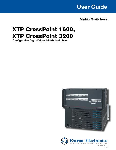
User Guide<br />
Matrix Switchers<br />
<strong>XTP</strong> <strong>CrossPoint</strong> <strong>1600</strong>,<br />
<strong>XTP</strong> <strong>CrossPoint</strong> <strong>3200</strong><br />
Configurable Digital Video Matrix Switchers<br />
68-1736-01 Rev. A<br />
12 13
Safety Instructions<br />
Safety Instructions • English<br />
WARNING: This symbol, , when used on the product, is intended to<br />
alert the user of the presence of uninsulated dangerous voltage within the<br />
product’s enclosure that may present a risk of electric shock.<br />
ATTENTION: This symbol, , when used on the product, is intended<br />
to alert the user of important operating <strong>and</strong> maintenance (servicing)<br />
instructions in the literature provided with the equipment.<br />
For information on safety guidelines, regulatory compliances, EMI/EMF<br />
compatibility, accessibility, <strong>and</strong> related topics, see the <strong>Extron</strong> Safety <strong>and</strong><br />
Regulatory Compliance Guide, part number 68-290-01, on the <strong>Extron</strong> website,<br />
www.extron.com.<br />
Instructions de sécurité • Français<br />
AVERTISSEMENT : Ce pictogramme, , lorsqu’il est utilisé sur le<br />
produit, signale à l’utilisateur la présence à l’intérieur du boîtier du produit<br />
d’une tension électrique dangereuse susceptible de provoquer un choc<br />
électrique.<br />
ATTENTION : Ce pictogramme, , lorsqu’il est utilisé sur le produit,<br />
signale à l’utilisateur des instructions d’utilisation ou de maintenance<br />
importantes qui se trouvent dans la documentation fournie avec le<br />
matériel.<br />
Pour en savoir plus sur les règles de sécurité, la conformité à la réglementation,<br />
la compatibilité EMI/EMF, l’accessibilité, et autres sujets connexes, lisez les<br />
informations de sécurité et de conformité <strong>Extron</strong>, réf. 68-290-01, sur le site<br />
<strong>Extron</strong>, www.extron.com.<br />
Sicherheitsanweisungen • Deutsch<br />
WARNUNG: Dieses Symbol auf dem Produkt soll den Benutzer<br />
darauf aufmerksam machen, dass im Inneren des Gehäuses dieses<br />
Produktes gefährliche Spannungen herrschen, die nicht isoliert sind<br />
und die einen elektrischen Schlag verursachen können.<br />
VORSICHT: Dieses Symbol auf dem Produkt soll dem Benutzer in der<br />
im Lieferumfang enthaltenen Dokumentation besonders wichtige Hinweise<br />
zur Bedienung und Wartung (Inst<strong>and</strong>haltung) geben.<br />
Weitere Informationen über die Sicherheitsrichtlinien, Produkth<strong>and</strong>habung,<br />
EMI/EMF-Kompatibilität, Zugänglichkeit und verw<strong>and</strong>te Themen finden Sie in<br />
den <strong>Extron</strong>-Richtlinien für Sicherheit und H<strong>and</strong>habung (Artikelnummer<br />
68-290-01) auf der <strong>Extron</strong>-Website, www.extron.com.<br />
Instrucciones de seguridad • Español<br />
ADVERTENCIA: Este símbolo, , cu<strong>and</strong>o se utiliza en el producto,<br />
avisa al usuario de la presencia de voltaje peligroso sin aislar dentro del<br />
producto, lo que puede representar un riesgo de descarga eléctrica.<br />
ATENCIÓN: Este símbolo, , cu<strong>and</strong>o se utiliza en el producto, avisa<br />
al usuario de la presencia de importantes instrucciones de uso y<br />
mantenimiento recogidas en la documentación proporcionada con el<br />
equipo.<br />
Para obtener información sobre directrices de seguridad, cumplimiento<br />
de normativas, compatibilidad electromagnética, accesibilidad y temas<br />
relacionados, consulte la Guía de cumplimiento de normativas y seguridad de<br />
<strong>Extron</strong>, referencia 68-290-01, en el sitio Web de <strong>Extron</strong>,www.extron.com.<br />
Инструкция по технике безопасности • Русский<br />
ПРЕДУПРЕЖДЕНИЕ: Данный символ, , если указан<br />
на продукте, предупреждает пользователя о наличии<br />
неизолированного опасного напряжения внутри корпуса<br />
продукта, которое может привести к поражению электрическим<br />
током.<br />
ВНИМАНИЕ: Данный символ, , если указан на продукте,<br />
предупреждает пользователя о наличии важных инструкций<br />
по эксплуатации и обслуживанию в руководстве,<br />
прилагаемом к данному оборудованию.<br />
Для получения информации о правилах техники безопасности,<br />
соблюдении нормативных требований, электромагнитной<br />
совместимости (ЭМП/ЭДС), возможности доступа и других<br />
вопросах см. руководство по безопасности и соблюдению<br />
нормативных требований <strong>Extron</strong> на сайте <strong>Extron</strong>: www.extron.com,<br />
номер по каталогу - 68-290-01.<br />
Chinese Simplified( 简 体 中 文 )<br />
警 告 : 产 品 上 的 这 个 标 志 意 在 警 告 用 户 该 产 品 机 壳 内 有 暴 露 的 危 险 电 压 ,<br />
有 触 电 危 险 。<br />
注 意 : 产 品 上 的 这 个 标 志 意 在 提 示 用 户 设 备 随 附 的 用 户 手 册 中 有<br />
重 要 的 操 作 和 维 护 ( 维 修 ) 说 明 。<br />
关 于 我 们 产 品 的 安 全 指 南 、 遵 循 的 规 范 、EMI/EMF 的 兼 容 性 、 无 障 碍<br />
使 用 的 特 性 等 相 关 内 容 , 敬 请 访 问 <strong>Extron</strong> 网 站 www.extron.com, 参 见<br />
<strong>Extron</strong> 安 全 规 范 指 南 , 产 品 编 号 68-290-01。<br />
Chinese Traditional( )<br />
警 告 : 若 產 品 上 使 用 此 符 號 , 是 為 了 提 醒 使 用 者 , 產 品 機 殼 內 存 在 著<br />
可 能 會 導 致 觸 電 之 風 險 的 未 絕 緣 危 險 電 壓 。<br />
注 意 若 產 品 上 使 用 此 符 號 , 是 為 了 提 醒 使 用 者 , 設 備 隨 附 的 用 戶 手 冊 中 有 重<br />
要 的 操 作 和 維 護 ( 維 修 ) 説 明 。<br />
有 關 安 全 性 指 導 方 針 、 法 規 遵 守 、EMI/EMF 相 容 性 、 存 取 範 圍 和 相 關 主 題 的 詳 細 資<br />
訊 , 請 瀏 覽 <strong>Extron</strong> 網 站 :www.extron.com, 然 後 參 閱 《<strong>Extron</strong> 安 全 性 與 法 規<br />
遵 守 手 冊 》, 準 則 編 號 68-290-01。<br />
Japanese<br />
警 告 : この 記 号 が 製 品 上 に 表 示 されている 場 合 は、 筐 体 内 に 絶 縁 されて<br />
いない 高 電 圧 が 流 れ、 感 電 の 危 険 があることを 示 しています。<br />
注 意 : この 記 号 が 製 品 上 に 表 示 されている 場 合 は、 本 機 の 取 扱 説 明 書<br />
に 記 載 されている 重 要 な 操 作 と 保 守 ( 整 備 )の 指 示 についてユーザーの 注<br />
意 を 喚 起 するものです。<br />
安 全 上 のご 注 意 、 法 規 厳 守 、EMI/EMF 適 合 性 、その 他 の 関 連 項 目 に<br />
ついては、エクストロンのウェブサイト www.extron.com より 『<strong>Extron</strong> Safety<br />
<strong>and</strong> Regulatory Compliance Guide』 (P/N 68-290-01) をご 覧 ください。<br />
Korean<br />
경고: 이 기호 가 제품에 사용될 경우, 제품의 인클로저 내에 있는<br />
접지되지 않은 위험한 전류로 인해 사용자가 감전될 위험이 있음을<br />
경고합니다.<br />
주의: 이 기호 가 제품에 사용될 경우, 장비와 함께 제공된 책자에 나와<br />
있는 주요 운영 및 유지보수(정비) 지침을 경고합니다.<br />
안전 가이드라인, 규제 준수, EMI/EMF 호환성, 접근성, 그리고 관련 항목에<br />
대한 자세한 내용은 <strong>Extron</strong> 웹 사이트(www.extron.com)의 <strong>Extron</strong> 안전 및<br />
규제 준수 안내서, 68-290-01 조항을 참조하십시오.
Conventions Used in this Guide<br />
Notifications<br />
The following notifications are used:<br />
WARNING: A warning indicates a situation that has the potential to result in death or<br />
severe injury.<br />
ATTENTION: Attention indicates a situation that may damage or destroy the product or<br />
associated equipment.<br />
NOTE: A note draws attention to important information.<br />
TIP:<br />
A tip provides a suggestion to make working with the application easier.<br />
Software Comm<strong>and</strong>s<br />
Specifications Availability<br />
Comm<strong>and</strong>s are written in the fonts shown here:<br />
^AR Merge Scene,,Op1 scene 1,1 ^B 51 ^W^C<br />
[01] R 0004 00300 00400 00800 00600 [02] 35 [17] [03]<br />
E X1$ *X1(* X2** X3!* X2( CE}<br />
NOTE: For comm<strong>and</strong>s <strong>and</strong> examples of computer or device responses mentioned<br />
in this guide, the character “0” is used for the number zero <strong>and</strong> “O” represents the<br />
capital letter “o.”<br />
Computer responses <strong>and</strong> directory paths that do not have variables are written in the font<br />
shown here:<br />
Reply from 208.132.180.48: bytes=32 times=2ms TTL=32<br />
C:\Program Files\<strong>Extron</strong><br />
Variables are written in slanted form as shown here:<br />
ping xxx.xxx.xxx.xxx —t<br />
SOH R Data STX Comm<strong>and</strong> ETB ETX<br />
Selectable items, such as menu names, menu options, buttons, tabs, <strong>and</strong> field names are<br />
written in the font shown here:<br />
From the File menu, select New.<br />
Click the OK button.<br />
Product specification are available on the <strong>Extron</strong> website, www.extron.com.
FCC Class A Notice<br />
This equipment has been tested <strong>and</strong> found to comply with the limits for a Class A digital device,<br />
pursuant to part 15 of the FCC rules. The Class A limits provide reasonable protection against harmful<br />
interference when the equipment is operated in a commercial environment. This equipment generates,<br />
uses, <strong>and</strong> can radiate radio frequency energy <strong>and</strong>, if not installed <strong>and</strong> used in accordance with the<br />
instruction manual, may cause harmful interference to radio communications. Operation of this<br />
equipment in a residential area is likely to cause interference. This interference must be corrected at<br />
the expense of the user.<br />
ATTENTION: The Twisted Pair Extension technology works with unshielded twisted pair (UTP)<br />
or shielded twisted pair (STP) cables; but, to ensure FCC Class A <strong>and</strong> CE compliance, STP<br />
cables <strong>and</strong> STP Connectors are required.<br />
For more information on safety guidelines, regulatory compliances, EMI/EMF compatibility,<br />
accessibility, <strong>and</strong> related topics, see the “<strong>Extron</strong> Safety <strong>and</strong> Regulatory Compliance<br />
Guide” on the <strong>Extron</strong> website.<br />
Copyright<br />
© 2013 <strong>Extron</strong> <strong>Electronics</strong>. All rights reserved.<br />
Trademarks<br />
All trademarks mentioned in this guide are the properties of their respective owners.<br />
The following registered trademarks ® , registered service marks (SM) , <strong>and</strong> trademarks (TM) are the property of<br />
RGB Systems, Inc. or <strong>Extron</strong> <strong>Electronics</strong>:<br />
Registered Trademarks (®)<br />
AVTrac, Cable Cubby, <strong>CrossPoint</strong>, eBUS, EDID Manager, EDID Minder, <strong>Extron</strong>, Flat Field, GlobalViewer, Hideaway, Inline, IP Intercom, IP Link,<br />
Key Minder, LockIt, MediaLink, PlenumVault, PoleVault, PowerCage, PURE3, Quantum, SoundField, SpeedMount, SpeedSwitch, System<br />
INTEGRATOR, TeamWork, TouchLink, V‐Lock, VersaTools, VN‐Matrix, VoiceLift, WallVault, WindoWall, <strong>XTP</strong>, <strong>and</strong> <strong>XTP</strong> Systems<br />
Registered Service Mark (SM) : S3 Service Support Solutions<br />
Trademarks ( )<br />
AAP, AFL (Accu‐Rate Frame Lock), ADSP (Advanced Digital Sync Processing), AIS (Advanced Instruction Set), Auto‐Image, CDRS (Class D<br />
Ripple Suppression), DDSP (Digital Display Sync Processing), DMI (Dynamic Motion Interpolation), Driver Configurator, DSP Configurator, DSVP<br />
(Digital Sync Validation Processing), FastBite, FOXBOX, IP Intercom HelpDesk, MAAP, MicroDigital, ProDSP, QS-FPC (QuickSwitch Front Panel<br />
Controller), Scope‐Trigger, SIS, Simple Instruction Set, Skew‐Free, SpeedNav, Triple‐Action Switching, XTRA, ZipCaddy, ZipClip
Contents<br />
Introduction............................................. 1<br />
About this Guide.............................................. 1<br />
About the <strong>XTP</strong> <strong>CrossPoint</strong> Switchers................. 2<br />
Endpoint Configuration................................ 3<br />
Input <strong>and</strong> Output Boards <strong>and</strong> Signal Types.... 4<br />
Features............................................................ 6<br />
Installation............................................... 9<br />
Setup <strong>and</strong> Installation Checklist......................... 9<br />
Rear Panel Cabling <strong>and</strong> Features..................... 10<br />
Input <strong>and</strong> Output Boards............................ 12<br />
Remote Control Ports.................................. 22<br />
Ethernet Connection................................... 22<br />
Reset Button <strong>and</strong> LED................................. 22<br />
Power......................................................... 22<br />
Front Panel Configuration Port <strong>and</strong><br />
Power LEDs.................................................... 23<br />
Operation................................................24<br />
Front Panel Controls <strong>and</strong> Indicators................. 24<br />
Input <strong>and</strong> Output Buttons........................... 26<br />
Control Buttons.......................................... 27<br />
I/O Controls................................................ 29<br />
Power LEDs................................................. 29<br />
Button Icons............................................... 30<br />
Front Panel Operations.................................... 30<br />
Definitions.................................................. 31<br />
Power......................................................... 31<br />
Front Panel Security Lockouts...................... 31<br />
Creating a Configuration............................ 32<br />
Viewing the Configuration.......................... 37<br />
Using Presets.............................................. 40<br />
Muting <strong>and</strong> Unmuting Video <strong>and</strong> Audio<br />
Outputs..................................................... 43<br />
Viewing <strong>and</strong> Adjusting the<br />
Input Audio Level....................................... 45<br />
Viewing <strong>and</strong> Adjusting the<br />
Analog Output Volume.............................. 51<br />
Setting the Front Panel Locks (Executive<br />
Modes)...................................................... 56<br />
Performing a System Reset from the Front<br />
Panel......................................................... 57<br />
Background Illumination............................. 58<br />
Selecting the Rear Panel Remote Port Protocol<br />
<strong>and</strong> Baud Rate........................................... 58<br />
Rear Panel Operations..................................... 60<br />
Performing a Hard Reset (Reset 1)............... 61<br />
Performing Soft System Resets<br />
(Resets 3, 4, <strong>and</strong> 5).................................... 62<br />
Optimizing the Analog Audio......................... 63<br />
Troubleshooting.............................................. 63<br />
Configuration Worksheets.............................. 64<br />
Worksheet Example 1: System Equipment... 64<br />
Worksheet Example 2: Daily Configuration. 65<br />
Worksheet Example 3: Test Configuration... 66<br />
<strong>XTP</strong> <strong>CrossPoint</strong> <strong>3200</strong> Switchers<br />
Configuration Worksheet........................... 67<br />
<strong>XTP</strong> <strong>CrossPoint</strong> <strong>1600</strong> Switchers<br />
Configuration Worksheet........................... 68<br />
Programming Guide...............................69<br />
Local Host-Control Ports................................. 70<br />
Ethernet (LAN) Port......................................... 70<br />
Default IP addresses.................................... 70<br />
Establishing a Connection........................... 71<br />
Connection Timeouts.................................. 71<br />
Number of Connections.............................. 71<br />
Using Verbose Mode................................... 71<br />
Host-to-Switcher Instructions.......................... 72<br />
Switcher-initiated Messages............................ 72<br />
Switcher Error Responses................................ 73<br />
Using the Comm<strong>and</strong> <strong>and</strong> Response Tables...... 73<br />
SIS Comm<strong>and</strong> <strong>and</strong> Response Table for<br />
Basic Matrix Switcher Comm<strong>and</strong>s.................. 79<br />
SIS Comm<strong>and</strong> <strong>and</strong> Response Table for<br />
Input-Board-Specific Comm<strong>and</strong>s.................... 80<br />
SIS Comm<strong>and</strong> <strong>and</strong> Response Table for<br />
Input-Endpoint-Specific Comm<strong>and</strong>s............... 88<br />
SIS Comm<strong>and</strong> <strong>and</strong> Response Table for<br />
Output-Board-Specific Comm<strong>and</strong>s................. 95<br />
SIS Comm<strong>and</strong> <strong>and</strong> Response Table for<br />
Output-Endpoint-Specific Comm<strong>and</strong>s............ 99<br />
SIS Comm<strong>and</strong> <strong>and</strong> Response Table for<br />
Advanced Matrix Switcher Comm<strong>and</strong>s......... 103<br />
SIS Comm<strong>and</strong> <strong>and</strong> Response Table for<br />
IP- <strong>and</strong> Remote Port-Specific Comm<strong>and</strong>s..... 109<br />
Special Characters........................................ 110<br />
<strong>XTP</strong> <strong>CrossPoint</strong> <strong>1600</strong> <strong>and</strong> <strong>3200</strong> Switchers • Contents<br />
v
HTML Operation.................................... 111<br />
Download the Startup Page.......................... 112<br />
Status Tab..................................................... 113<br />
System Status Page................................... 113<br />
DSVP Page................................................ 114<br />
HDCP Page............................................... 115<br />
Configuration Tab......................................... 116<br />
System Settings Page................................ 116<br />
Passwords Page........................................ 119<br />
Email Settings Page................................... 120<br />
Firmware Upgrade Page............................ 122<br />
File Management Tab.................................... 125<br />
File Management Page.............................. 125<br />
Control Tab................................................... 126<br />
Set <strong>and</strong> View Ties page............................. 126<br />
Input Adjustments Page............................ 127<br />
Output Adjustments Page......................... 129<br />
EDID Configuration Page.......................... 131<br />
<strong>XTP</strong> Power Page........................................ 132<br />
Global Presets Page................................... 133<br />
Ethernet Connection............................ 140<br />
Ethernet Link................................................ 140<br />
Ethernet Connection................................. 140<br />
Default IP Address..................................... 140<br />
Pinging to Determine the<br />
<strong>Extron</strong> IP Address..................................... 141<br />
Pinging to Determine the<br />
Web IP Address........................................ 141<br />
Configuring the <strong>XTP</strong> <strong>CrossPoint</strong> Switcher<br />
for Network Use via the ARP Comm<strong>and</strong>... 142<br />
Connecting as a Telnet Client.................... 143<br />
Telnet Tips................................................. 143<br />
Subnetting — A Primer................................. 145<br />
Gateways.................................................. 145<br />
Analog <strong>and</strong> Remote Devices...................... 145<br />
IP Addresses <strong>and</strong> Octets............................ 145<br />
Subnet Masks <strong>and</strong> Octets.......................... 146<br />
Determining Whether Devices Are on the<br />
Same Subnet........................................... 146<br />
Maintenance <strong>and</strong> Modifications.......... 134<br />
Mounting the Switcher................................. 134<br />
UL Guidelines............................................ 134<br />
Mounting Instructions............................... 134<br />
Removing <strong>and</strong> Installing an Input or<br />
Output Board or Blank Panel........................ 135<br />
Removing an Input or Output Board or<br />
Blank Panel.............................................. 135<br />
Installing an Input or Output Board or<br />
Blank Panel.............................................. 136<br />
Removing <strong>and</strong> Installing Button Labels.......... 136<br />
Making Labels Using the Button-Label<br />
Generator Program.................................. 136<br />
Making Labels from Paper Templates........ 137<br />
Installing Labels in the Buttons.................. 138<br />
<strong>XTP</strong> <strong>CrossPoint</strong> <strong>1600</strong> <strong>and</strong> <strong>3200</strong> Switchers • Contents<br />
vi
IR<br />
STANDBY/ON<br />
CONFIG<br />
CHANNEL<br />
SDTV<br />
EDTV<br />
HDTV<br />
PQLS HDMI OPEN/CLOSE FL OFF<br />
USB<br />
POWER<br />
12V<br />
--A MAX<br />
POWER<br />
12V<br />
--A MAX<br />
POWER<br />
12V<br />
--A MAX<br />
PWR HDCP HDMI PC<br />
HDMI INPUT<br />
NET<br />
ACT LINK<br />
INPUTS<br />
SIG LINK<br />
<strong>XTP</strong> T USW 103<br />
OVER <strong>XTP</strong><br />
AUDIO RS-232 IR CONTACT RS-232<br />
RESET<br />
1 2<br />
3 <strong>XTP</strong> OUT ACT NET LINK Tx Rx Tx Rx 1 2 3 Tx Rx<br />
MENU NEXT<br />
HDMI<br />
AUDIO INPUT<br />
COMPUTER IN<br />
ADJUST<br />
INPUTS<br />
HDMI AUDIO<br />
AUDIO INPUT<br />
ON<br />
ANALOG<br />
LOOP-THRU OFF <strong>XTP</strong> T HDMI HDMI<br />
UNIVERSAL<br />
YUV VID<br />
YUV VIDEO<br />
Y<br />
Pb<br />
Pr<br />
VOLUME<br />
AVT 200HD<br />
ATSC TUNER<br />
INPUTS<br />
LOOP-THRU<br />
AUDIO<br />
L<br />
R<br />
+ − + −<br />
AUDIO<br />
L R<br />
+ − + −<br />
OVER <strong>XTP</strong><br />
RS-232 IR<br />
Tx Rx<br />
Tx Rx<br />
Tx Rx<br />
OVER <strong>XTP</strong><br />
AUDIO<br />
RS-232 IR<br />
Tx Rx<br />
SIG<br />
LINK<br />
<strong>XTP</strong> OUT<br />
SIG<br />
LINK<br />
ACT LINK<br />
NET<br />
<strong>XTP</strong> OUT ACT LINK<br />
NET<br />
RESET<br />
<strong>XTP</strong> T VGA<br />
RESET<br />
100-240V 50-60Hz<br />
5A MAX<br />
1 2 COM1 COM2 COM3 COM7 1 2 3 4 1 2 3 4<br />
TX RX TX RX TX RX TX RX RTS CTS S G S G S G S G<br />
SWITCHED 12VDC<br />
IR/SERIAL<br />
40W MAX TOTAL<br />
3 4 COM4 COM5 COM6 COM8 5<br />
TX RX<br />
TX RX<br />
100-240V -- A MAX<br />
50-60Hz<br />
TX RX<br />
TX RX<br />
RTS CTS<br />
S G S G<br />
6 7<br />
S G S G<br />
1−4<br />
5−8<br />
9−12<br />
13−16<br />
1−4<br />
5−8<br />
9−12<br />
13−16<br />
RELAY<br />
8 5 6 7 8<br />
PWR<br />
PWR<br />
SIG<br />
SIG<br />
<strong>XTP</strong><br />
<strong>XTP</strong><br />
LINK<br />
LINK<br />
ACT<br />
ACT<br />
LAN<br />
eBUS<br />
+V D -S+S<br />
PWR OUT = 12W<br />
FLEX I/O<br />
1 2 3 4<br />
REMOTE<br />
RS-232/RS-422<br />
LAN<br />
LINK<br />
LINK<br />
PWR<br />
PWR<br />
SIG<br />
SIG<br />
<strong>XTP</strong><br />
<strong>XTP</strong><br />
LINK<br />
LINK<br />
LINK<br />
LAN<br />
ACT<br />
LAN<br />
ACT<br />
ACT<br />
LAN<br />
LAN<br />
LINK<br />
LINK<br />
PWR<br />
PWR<br />
SIG<br />
SIG<br />
<strong>XTP</strong><br />
RESET<br />
<strong>XTP</strong><br />
LINK<br />
LINK<br />
ACT<br />
ACT<br />
LAN<br />
LAN<br />
LINK<br />
LINK<br />
PWR<br />
PWR<br />
SIG<br />
SIG<br />
<strong>XTP</strong><br />
<strong>XTP</strong><br />
LINK<br />
LINK<br />
ACT<br />
ACT<br />
LAN<br />
LAN<br />
LINK<br />
LINK<br />
RS-232<br />
Tx Rx<br />
IR<br />
Tx Rx<br />
RS-232<br />
Tx Rx<br />
IR<br />
Tx Rx<br />
AUDIO<br />
L R L R L R L R<br />
RS-232<br />
Tx Rx<br />
IR<br />
Tx Rx<br />
RS-232<br />
Tx Rx<br />
IR/RS-232 OVER <strong>XTP</strong><br />
IR<br />
Tx Rx<br />
AUDIO<br />
L R L R L R L R<br />
AUDIO<br />
L R L R L R L R<br />
AUDIO<br />
AUDIO<br />
RS-232<br />
Tx Rx<br />
L R L R L R L R<br />
IR<br />
Tx Rx<br />
RS-232<br />
Tx Rx<br />
IR<br />
Tx Rx<br />
L R L R L R L R<br />
AUDIO<br />
L R L R L R L R<br />
IR/RS-232 OVER <strong>XTP</strong><br />
RS-232<br />
Tx Rx<br />
IR<br />
Tx Rx<br />
RS-232<br />
Tx Rx<br />
IR<br />
Tx Rx<br />
<strong>XTP</strong> CP 4i HDMI<br />
<strong>XTP</strong> CP 4i DVI Pro<br />
<strong>XTP</strong> CP 4i<br />
<strong>XTP</strong> CP 4i VGA<br />
<strong>XTP</strong> CP 4o HDMI<br />
<strong>XTP</strong> CP 4o DVI Pro<br />
<strong>XTP</strong> CP 4o<br />
<strong>XTP</strong> CP 4o SA<br />
POWER<br />
12V<br />
--A MAX<br />
POWER<br />
12V<br />
--A MAX<br />
100-240V 1.3A, 50-60Hz<br />
SIG<br />
<strong>XTP</strong> IN<br />
SIG<br />
LINK<br />
<strong>XTP</strong> IN<br />
ACT LINK<br />
NET<br />
LINK<br />
C<br />
LISTED<br />
ACT LINK<br />
NET<br />
OVER <strong>XTP</strong><br />
RS-232 IR<br />
Tx Rx<br />
OUTPUTS<br />
OVER <strong>XTP</strong> HDMI AUDIO<br />
AUDIO<br />
RS-232 IR ON<br />
L R<br />
Tx Rx<br />
Tx Rx<br />
HDMI AUDIO<br />
ON<br />
OFF<br />
HDMI<br />
OUTPUTS<br />
S/PDIF<br />
AUDIO<br />
RELAYS<br />
L R 1 2<br />
+ − + −<br />
Tx Rx OFF<br />
HDMI + - + -<br />
S/PDIF<br />
17TT<br />
XPA 1002<br />
US AUDIO/VIDEO<br />
APPARATUS<br />
CLASS 2 WIRING<br />
LEVEL<br />
INPUTS REMOTE<br />
OUTPUT<br />
1 2<br />
1<br />
1 2<br />
2<br />
10V 50 mA<br />
LIMITER/<br />
VOL/MUTE<br />
1 2<br />
PROTECT<br />
SIGNAL<br />
0 0<br />
STANDBY<br />
<strong>XTP</strong> SR HDMI<br />
REMOTE<br />
RS-232<br />
RESET<br />
Tx Rx<br />
<strong>XTP</strong> R HDMI<br />
RELAYS<br />
1 2 RESET<br />
Introduction<br />
About this Guide<br />
• About this Guide<br />
• About the <strong>XTP</strong> <strong>CrossPoint</strong> Switchers<br />
• Features<br />
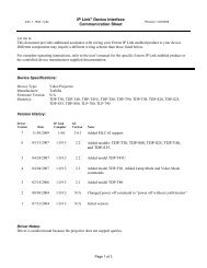
This guide contains installation, configuration, <strong>and</strong> operating information for the <strong>Extron</strong><br />
<strong>XTP</strong> <strong>CrossPoint</strong> <strong>1600</strong> Matrix Switcher (see figure 1) <strong>and</strong> <strong>CrossPoint</strong> <strong>3200</strong> Matrix Switcher.<br />
These customizable matrix switchers support up to 16 (<strong>XTP</strong> <strong>CrossPoint</strong> <strong>1600</strong>) or<br />
32 (<strong>XTP</strong> <strong>CrossPoint</strong> <strong>3200</strong>) inputs <strong>and</strong> outputs.<br />
NOTE: In this guide, the terms “<strong>XTP</strong> <strong>CrossPoint</strong> switchers” <strong>and</strong> “switchers” refers to<br />
either switcher model unless otherwise specified.<br />
Cable Cubby 600<br />
with AAPs<br />
<strong>XTP</strong> T USW 103<br />
AV Control<br />
Network<br />
+-+-<br />
Ethernet<br />
Ethernet<br />
TLP 1000<br />
House Network Switch<br />
COMPUTER AUDIO<br />
Laptop<br />
HDMI<br />
Ethernet<br />
AVT 200 HD<br />
VGA<br />
HDMI<br />
HDMI<br />
Ethernet<br />
<strong>XTP</strong> T UWP 304<br />
AUDIO L<br />
R<br />
CAT 5-type Cable<br />
HDMI with embedded audio<br />
+-+-<br />
IPCP 505<br />
RS-232 IR<br />
Ethernet<br />
INPUTS<br />
IN<br />
IN<br />
IN<br />
IN<br />
Ethernet<br />
IN<br />
IN<br />
IN<br />
IN<br />
Ethernet<br />
IR<br />
HDMI<br />
<strong>XTP</strong> SR HDMI<br />
Ethernet<br />
RS-232<br />
HDMI<br />
Flat Panel Display<br />
Flat Panel Display<br />
Blu-ray Player<br />
Ethernet<br />
OUT<br />
OUT<br />
<strong>XTP</strong> R HDMI<br />
PC<br />
HDMI<br />
VGA<br />
Ethernet<br />
IR<br />
<strong>XTP</strong> T HDMI<br />
OUTPUTS<br />
OUT<br />
OUT<br />
OUT<br />
<strong>Extron</strong><br />
<strong>XTP</strong> <strong>CrossPoint</strong> <strong>1600</strong><br />
OUT<br />
OUT<br />
OUT<br />
HDMI<br />
Stereo Audio<br />
SI 28<br />
Flat Panel Display<br />
<strong>XTP</strong> T VGA<br />
XPA 1002<br />
Figure 1.<br />
Typical <strong>XTP</strong> <strong>CrossPoint</strong> <strong>1600</strong> Application<br />
<strong>XTP</strong> <strong>CrossPoint</strong> <strong>1600</strong> <strong>and</strong> <strong>3200</strong> Switchers • Introduction 1
About the <strong>XTP</strong> <strong>CrossPoint</strong> Switchers<br />
The <strong>XTP</strong> <strong>CrossPoint</strong> matrix switchers are configurable, modular matrix switchers that<br />
distribute a variety of video <strong>and</strong> audio types, depending on how it is configured. A matrix<br />
switcher routes any input signal to any combination of outputs. It can route multiple input<br />
<strong>and</strong> output configurations simultaneously.<br />
The <strong>XTP</strong> <strong>CrossPoint</strong> models are assembled from user-installed <strong>and</strong> hot-swappable input<br />
<strong>and</strong> output boards. Table 1 identifies the four types of input boards <strong>and</strong> four types of output<br />
boards currently available, each of which can receive (input boards) or output (output<br />
boards) up to four signals. See Input <strong>and</strong> Output Boards <strong>and</strong> Signal Types on page 4<br />
for details.<br />
Table 1. Available Input <strong>and</strong> Output Boards<br />
Input Boards<br />
<strong>XTP</strong> CP 4i (<strong>XTP</strong> input board)<br />
Receives inputs from <strong>Extron</strong> <strong>XTP</strong> transmitters <strong>and</strong> local<br />
serial port <strong>and</strong> IR inserts.<br />
<strong>XTP</strong> CP 4i HDMI (HDMI ® input board)<br />
Receives HDMI signals <strong>and</strong> analog audio inputs<br />
<strong>XTP</strong> CP 4i DVI Pro (DVI Pro input board)<br />
Receives DVI Pro signals <strong>and</strong> analog audio inputs<br />
<strong>XTP</strong> CP 4i VGA (universal analog VGA input board)<br />
Receives RGBHV, RGBs, RGsB, HDTV <strong>and</strong> YUV<br />
component video, S-Video <strong>and</strong> composite video analog<br />
inputs <strong>and</strong> analog audio inputs.<br />
Output Boards<br />
<strong>XTP</strong> CP 4o (<strong>XTP</strong> output board)<br />
Outputs signals to <strong>Extron</strong> <strong>XTP</strong> receivers. Includes local<br />
serial port <strong>and</strong> IR inserts.<br />
<strong>XTP</strong> CP 4o HDMI (HDMI output board)<br />
Outputs HDMI <strong>and</strong> analog audio outputs. Output is<br />
HDCP-compliant if the input is HDCP-compliant.<br />
<strong>XTP</strong> CP 4o DVI Pro (DVI Pro output board)<br />
Outputs DVI Pro signals <strong>and</strong> analog audio outputs.<br />
<strong>XTP</strong> CP 4o SA<br />
(Analog audio output board)<br />
Outputs analog audio outputs.<br />
The <strong>XTP</strong> <strong>CrossPoint</strong> <strong>1600</strong> can support up to four input boards <strong>and</strong> four output boards<br />
of any of the type listed above. The <strong>XTP</strong> <strong>CrossPoint</strong> <strong>3200</strong> can support up to eight input<br />
boards <strong>and</strong> eight output boards. The input boards convert their non-<strong>XTP</strong> inputs into the<br />
digital <strong>XTP</strong> format used by <strong>Extron</strong> <strong>XTP</strong> transmitters <strong>and</strong> receivers <strong>and</strong> place them on the<br />
switcher backplane. The output boards with non-<strong>XTP</strong> outputs convert the <strong>XTP</strong> signal to<br />
the appropriate format for that output board type. Thus, as a system, the <strong>XTP</strong> <strong>CrossPoint</strong><br />
switchers can transcode inputs in any valid format to the output formats supported by the<br />
family of output boards, making them single box solutions to complex digital video signal<br />
routing applications. Each input <strong>and</strong> output is individually isolated <strong>and</strong> buffered, <strong>and</strong> any<br />
input can be switched to any one or all outputs with virtually no crosstalk or signal noise<br />
between channels<br />
By adding or removing I/O boards within certain rules that are detailed in Input <strong>and</strong><br />
Output Boards, on page 12, you can exp<strong>and</strong> <strong>and</strong> contract the switcher from a 4-input by<br />
4-output matrix to up to either:<br />
• <strong>XTP</strong> <strong>CrossPoint</strong> <strong>1600</strong> — A 16-input by 16-output matrix<br />
• <strong>XTP</strong> <strong>CrossPoint</strong> <strong>3200</strong> — A 32-input by 32-output matrix<br />
<strong>XTP</strong> <strong>CrossPoint</strong> <strong>1600</strong> <strong>and</strong> <strong>3200</strong> Switchers • Introduction 2
The matrix switchers can be remotely controlled via their rear panel Remote RS-232/RS-422<br />
ports, their rear panel LAN port, <strong>and</strong> their front panel Configuration (USB) port by any of the<br />
following:<br />
• A control system<br />
• A PC<br />
• An <strong>Extron</strong> MKP 2000 remote control panel<br />
• an <strong>Extron</strong> MKP 3000 remote control panel<br />
• (RS-232/RS-422 only) An <strong>Extron</strong> MCP 1000 remote control panel<br />
• (RS-232/RS-422 only) An <strong>Extron</strong> MKP 1000 remote keypad<br />
Control can be via the <strong>Extron</strong> <strong>XTP</strong> Configuration Software, the Simple Instruction Set (SIS),<br />
or HTML pages (LAN port control only). The SIS is a set of basic ASCII code comm<strong>and</strong>s<br />
(see Programming Guide on page 69) that provide simple control through a control<br />
system or PC. The built-in web pages (see HTML Operation on page 111) can be access<br />
via the LAN port using a web browser such as the Microsoft Internet Explorer.<br />
The matrix switchers are housed in rack-mountable, 5U (<strong>XTP</strong> <strong>CrossPoint</strong> <strong>1600</strong>) or<br />
10U (<strong>XTP</strong> <strong>CrossPoint</strong> 3600) high metal enclosures with mounting flanges for st<strong>and</strong>ard<br />
19-inch racks.<br />
The <strong>XTP</strong> <strong>CrossPoint</strong> <strong>3200</strong> ships with three 12 V internal power supplies <strong>and</strong> one 48 V<br />
power supply, on a single AC connection. The switcher can operate using two of the 12 V<br />
supplies with the third as a hot backup. The fourth supply provides power over the <strong>XTP</strong><br />
connection to remote devices (Power over <strong>XTP</strong> [PoX]).<br />
The base <strong>XTP</strong> <strong>CrossPoint</strong> <strong>1600</strong> ships with two internal power supplies on a single AC<br />
connection that provide 12 V <strong>and</strong> 48 V. It can be ordered with two additional optional<br />
redundant (12 V <strong>and</strong> 48 V) power supplies. The customer cannot install the redundant<br />
power supplies.<br />
The 100 VAC to 240 VAC, 50-60 Hz power supplies provide worldwide power compatibility<br />
<strong>and</strong> reliability. Front panel LEDs indicate good <strong>and</strong> failed status for each supply.<br />
Endpoint Configuration<br />
In an <strong>XTP</strong> system, the transmitters connected to the input boards <strong>and</strong> the receivers<br />
connected to the output boards are known as “endpoints”.<br />
When you configure an <strong>XTP</strong> system (consisting of an <strong>XTP</strong> <strong>CrossPoint</strong> Matrix switcher <strong>and</strong><br />
its connected endpoints), connect a computer to the matrix switcher <strong>and</strong> configure the<br />
endpoints from the matrix switcher. Do not connect the computer directly to the endpoint<br />
for configuration when it is part of an <strong>XTP</strong> system.<br />
<strong>XTP</strong> <strong>CrossPoint</strong> <strong>1600</strong> <strong>and</strong> <strong>3200</strong> Switchers • Introduction 3
Input <strong>and</strong> Output Boards <strong>and</strong> Signal Types<br />
The <strong>XTP</strong> <strong>CrossPoint</strong> matrix switchers are assembled from user-installed <strong>and</strong> hot-swappable<br />
input <strong>and</strong> output boards. This section details the signals types processed by each board<br />
<strong>and</strong> the function of boards.<br />
The boards have a primary signal type that is identified by the name of the board <strong>and</strong> used<br />
as the subsections of the “Primary signal type, by board” section, below. Most boards have<br />
secondary signal types that are used as the subsections of the Secondary signal type on<br />
page 6.<br />
See table 2 <strong>and</strong> the following subsections for an explanation of the various input <strong>and</strong> output<br />
boards capabilities.<br />
Table 2. Available Input <strong>and</strong> Output Boards <strong>and</strong> Applicable Signal Types<br />
<strong>XTP</strong> CP 4i<br />
(<strong>XTP</strong> input board)<br />
Signal Type<br />
<strong>XTP</strong> input<br />
<strong>XTP</strong> output<br />
HDMI input<br />
HDMI output<br />
DVI Pro input<br />
DVI pro output<br />
Analog video (VGA) input<br />
Remote power<br />
RS-232 inserts<br />
Dedicated UARTs<br />
Local audio input<br />
Local audio output<br />
(<strong>XTP</strong> output board)<br />
•<br />
•<br />
•<br />
•<br />
(HDMI input board)<br />
<strong>XTP</strong> CP 4o<br />
<strong>XTP</strong> CP 4o HDMI<br />
(HDMI output board)<br />
<strong>XTP</strong> CP 4i HDMI<br />
•<br />
•<br />
•<br />
•<br />
<strong>XTP</strong> CP 4i DVI Pro<br />
(DVI Pro input board)<br />
•<br />
•<br />
<strong>XTP</strong> CP 4o DVI Pro<br />
(DVI Pro output board)<br />
•<br />
•<br />
(Analog video input board)<br />
•<br />
•<br />
(Analog audio output board)<br />
<strong>XTP</strong> CP 4i VGA<br />
•<br />
•<br />
<strong>XTP</strong> CP 4o SA<br />
•<br />
•<br />
•<br />
Primary signal type, by board<br />
<strong>XTP</strong> input <strong>and</strong> output boards<br />
The <strong>XTP</strong> boards are essentially receivers (input boards) <strong>and</strong> transmitters (output boards).<br />
The input board receives up to four <strong>XTP</strong> inputs, on either <strong>Extron</strong> <strong>XTP</strong> DTP 24 SF/UTP cable<br />
or Category (CAT) 5e, 6, or 7 twisted pair (TP) cable, terminated with RJ-45 connectors,<br />
from <strong>Extron</strong> <strong>XTP</strong> transmitters.<br />
The output board transmits <strong>XTP</strong> signals to as many as four <strong>XTP</strong> receivers.<br />
The <strong>XTP</strong> signals can include digital video signals (or digitized analog video if the tied<br />
input is from a universal VGA input board), audio, RS-232, IR, Ethernet, <strong>and</strong> remote<br />
power capability. A second RJ-45 connector is present that allows you to insert Ethernet<br />
communications onto the <strong>XTP</strong> cable to passively extend them to a LAN (Ethernet) port on<br />
the connected endpoint. The maximum transmission distance is 330 feet (100 m).<br />
Each <strong>XTP</strong> board features remote power (48 VDC @ 13 watts per output) on the <strong>XTP</strong> inputs<br />
<strong>and</strong> outputs for <strong>XTP</strong> transmitters <strong>and</strong> receivers.<br />
Both <strong>XTP</strong> boards also support RS-232 inputs <strong>and</strong> dedicated universal asynchronous<br />
receiver/transmitters (UARTs) (see Serial port inserts <strong>and</strong> Dedicated UARTs, both on<br />
page 6).<br />
<strong>XTP</strong> <strong>CrossPoint</strong> <strong>1600</strong> <strong>and</strong> <strong>3200</strong> Switchers • Introduction 4
HDMI <strong>and</strong> DVI Pro input <strong>and</strong> output boards<br />
The HDMI input board has four HDMI input connectors. The HDMI output board has four<br />
HDMI output connectors. The boards also support digital DVI-D signals with adapters.<br />
The DVI Pro input board has four DVI-I input connectors. The DVI Pro output board has<br />
four DVI-I output connectors. Although equipped with DVI-I connectors, the DVI Pro boards<br />
support digital DVI-D signals (<strong>and</strong> HDMI connectors with adapters) only.<br />
The boards meet the DVI 1.0 <strong>and</strong> HDMI 1.3 specifications, support a maximum resolution of<br />
1920 x 1200 @ 60 Hz <strong>and</strong> 1080p @ 60 Hz (deep color), <strong>and</strong> are HDCP-compliant.<br />
The output boards perform down-conversion automatic color bit depth to match the signal<br />
to display capabilities.<br />
All video input boards support 256 bytes of EDID <strong>and</strong> can save, import, <strong>and</strong> export EDID<br />
data.<br />
HDMI input boards <strong>and</strong> DVI Pro input boards both also have four analog balanced stereo<br />
inputs on captive screw connectors (see Analog audio inputs on page 6). HDMI output<br />
boards <strong>and</strong> DVI Pro output boards both also have four analog balanced stereo outputs on<br />
captive screw connectors (see Analog audio outputs on page 6).<br />
Analog audio output boards<br />
The audio output board has four analog stereo audio output connectors for balanced or<br />
unbalanced 2-channel audio. These boards extract 2-channel audio from the embedded<br />
stream for analog audio outputs with mute <strong>and</strong> audio volume controls<br />
VGA universal analog input boards<br />
The VGA universal analog video input board accepts RGBHV, RGBS, RGsB, HDTV<br />
component video, YUV component video, S-video, or composite video on 15-pin HD<br />
connectors. S-video <strong>and</strong> composite video require BNC to VGA adapters. The inputs feature<br />
auto-detect as the default condition, which automatically recognizes the input signal with no<br />
user configuration. The input format can also be forced via remote control.<br />
The universal inputs converts the incoming signal to digital Transition Minimized Differential<br />
Signaling (TMDS, the core technology used in HDMI <strong>and</strong> DVI) before converting to the <strong>XTP</strong><br />
format used on the backplane. The board de-interlaces <strong>and</strong> digitizes S-video <strong>and</strong> composite<br />
video to NTSC 480p or PAL 576p.<br />
The VGA input board can deliver one block of 128 bytes of analog DDC/EDID h<strong>and</strong>shake<br />
data for each input that can be used as an EDID reference for each of the source devices. If<br />
no output references are stored, the switcher can use one of the stored EDID data files<br />
The VGA universal analog video input board also have four analog balanced stereo inputs<br />
on captive screw connectors (see Analog audio inputs).<br />
<strong>XTP</strong> <strong>CrossPoint</strong> <strong>1600</strong> <strong>and</strong> <strong>3200</strong> Switchers • Introduction 5
Secondary signal type<br />
Serial port inserts<br />
The <strong>XTP</strong> input <strong>and</strong> output boards also have four local RS-232 <strong>and</strong> IR insert inputs on<br />
captive screw connectors. The insert inputs support up to a 115k baud rate. Each RS-232<br />
<strong>and</strong> IR insert <strong>and</strong> local output is for the associated input or output only <strong>and</strong> cannot be tied<br />
to other outputs or inputs.<br />
Dedicated UARTs<br />
The <strong>XTP</strong> <strong>CrossPoint</strong> switch can send data strings to inputs <strong>and</strong> outputs on the <strong>XTP</strong> boards<br />
using dedicated UART ports. Each <strong>XTP</strong> input <strong>and</strong> output has a dedicated UART port to<br />
allow bidirectional communication on every <strong>XTP</strong> port simultaneously. Once the Ethernet-to-<br />
RS-232 feature is enabled, via the <strong>XTP</strong> Configuration Software or an SIS comm<strong>and</strong>, the <strong>XTP</strong><br />
input or output is unable to pass any RS-232 comm<strong>and</strong>s from the local insert connections<br />
on the I/O board but instead passes the communications via the UART.<br />
Analog audio inputs<br />
Boards listed in table 2 on page 4 as supporting analog audio input have four stereo audio<br />
input captive screw connectors for balanced or unbalanced 2-channel audio. These boards<br />
can perform analog-to-digital conversion of analog audio inputs for audio breakaway ties.<br />
Analog audio input levels can be adjusted through a range of +24 dB gain through –18 dB<br />
attenuation.<br />
Analog audio outputs<br />
Boards listed in table 2 as supporting analog audio output have four stereo audio output<br />
captive screw connectors for balanced or unbalanced 2-channel audio. These boards<br />
extract 2-channel audio from the embedded stream for analog audio outputs with mute <strong>and</strong><br />
audio volume controls<br />
Features<br />
Available in I/O sizes from 4x4 to 32x32 — System configuration is flexible to match a<br />
wide variety of small to large-sized installations.<br />
15.2 Gbps data-rate digital backplane — Ensures switching <strong>and</strong> distribution of video<br />
signals without degradation, offering the performance required to maintain signal integrity<br />
with the most dem<strong>and</strong>ing high resolution signals.<br />
Compatible with all <strong>XTP</strong> integrated system products — <strong>XTP</strong> <strong>CrossPoint</strong> is<br />
a flexible, reliable signal switching <strong>and</strong> distribution system that provides a completely<br />
integrated solution for multiple digital <strong>and</strong> analog formats.<br />
Fully digital signal routing — Analog signals are digitized, sending a reliable, high quality<br />
digital video signal to the output destination.<br />
Wide selection of input <strong>and</strong> output boards — Boards provide integration for a variety<br />
of signal types <strong>and</strong> formats, ensuring system customization appropriate for a wide range of<br />
applications.<br />
Serial port insertion from the Ethernet control port — System level device control<br />
to all remote locations via the Ethernet port of the matrix switcher, providing comprehensive<br />
control of endpoints <strong>and</strong> attached devices without needing additional cabling.<br />
Remote power to <strong>XTP</strong> transmitters <strong>and</strong> receivers — To simplify installation in spacechallenged<br />
locations, an <strong>XTP</strong> <strong>CrossPoint</strong> matrix switcher can provide power to remote <strong>XTP</strong><br />
transmitters <strong>and</strong> receivers over the same TP cable that is used for sending AV signals. This<br />
avoids the need for external power supplies at remote endpoints.<br />
<strong>XTP</strong> <strong>CrossPoint</strong> <strong>1600</strong> <strong>and</strong> <strong>3200</strong> Switchers • Introduction 6
HDMI 1.3 compatible — Supports HDMI 1.3 specification features, including data rates<br />
up to 6.75 Gbps, Deep Color up to 12-bit, 3D formats, Lip Sync, <strong>and</strong> HD lossless audio<br />
formats.<br />
HDCP compliant — Ensures display of content-protected media <strong>and</strong> interoperability with<br />
other HDCP-compliant devices.<br />
HDCP authentication <strong>and</strong> signal confirmation via RS-232 or Ethernet — The<br />
<strong>XTP</strong> <strong>CrossPoint</strong> provides real-time verification of HDCP status for each digital video input<br />
<strong>and</strong> output. This allows for simple, quick, <strong>and</strong> easy signal <strong>and</strong> HDCP verification through<br />
RS-232/RS-422 or Ethernet, providing valuable feedback to a system operator or helpdesk<br />
support staff.<br />
HDCP Visual Confirmation provides a green signal when encrypted content<br />
is sent to a non-compliant display — A full-screen green signal is sent when HDCPencrypted<br />
content is transmitted to a non-HDCP compliant display, providing immediate<br />
visual confirmation that protected content cannot be viewed on the display.<br />
SpeedSwitch Technology — Provides exceptional switching speed for HDCP-encrypted<br />
content.<br />
SD Pro processing provides deinterlacing of st<strong>and</strong>ard definition video —<br />
Deinterlaces 480i <strong>and</strong> 576i signals for compatibility with HDMI <strong>and</strong> DVI-equipped displays,<br />
without the need for additional scalers.<br />
EDID Minder — Automatically manages EDID communication between connected<br />
devices, ensuring that all sources power up properly <strong>and</strong> reliably output content for display.<br />
Key Minder — Continuously verifies HDCP compliance for quick, reliable switching.<br />
Authenticates <strong>and</strong> maintains continuous HDCP encryption between input <strong>and</strong> output<br />
devices to ensure quick <strong>and</strong> reliable switching in professional AV environments, while<br />
enabling simultaneous distribution of a single source signal to one or more displays.<br />
Modular, field-upgradeable <strong>and</strong> hot-swappable design — The <strong>XTP</strong> <strong>CrossPoint</strong><br />
provides substantial flexibility, exp<strong>and</strong>ability, <strong>and</strong> affordability by allowing users to select the<br />
configuration required for a system. Additional input <strong>and</strong> output boards may be added at<br />
any time for quick <strong>and</strong> easy upgradeability or expansion. Hot-swappable components allow<br />
the user to replace an I/O board at any time without the need to power down the switcher.<br />
This is especially useful for mission-critical applications that require continuous system<br />
operation.<br />
Audio breakaway — Provides the capability to separate an embedded audio signal from<br />
its corresponding video signal within the matrix switcher, allowing the audio <strong>and</strong> video<br />
signals from one source to be switched to different destinations.<br />
Ethernet extension — Centralized 10/100 Ethernet communication can be implemented<br />
via an Ethernet pass-through port to reduce the amount of independent network drops<br />
required within a system.<br />
Digital output boards provide +5 VDC, 250 mA power on each output for<br />
powering external peripheral devices — Power provided via the digital output of a<br />
board eliminates the need of a separate power supply for the connected peripheral device.<br />
Automatic cable equalization for each digital input to 100 feet (30 m) when<br />
used with <strong>Extron</strong> HDMI or DVI Pro cables — Cable input equalization optimizes signal<br />
performance for all incoming signals, ensuring pristine image quality is delivered throughout<br />
an <strong>XTP</strong> <strong>CrossPoint</strong> System.<br />
Automatic output reclocking — Reshapes <strong>and</strong> restores timing of digital video signals<br />
at each output, eliminating high frequency jitter to ensure reliable transmission over long<br />
cables.<br />
<strong>XTP</strong> <strong>CrossPoint</strong> <strong>1600</strong> <strong>and</strong> <strong>3200</strong> Switchers • Introduction 7
Audio input gain <strong>and</strong> attenuation — Allows the level of gain or attenuation to be set,<br />
eliminating noticeable volume differences when switching between sources.<br />
Audio output volume adjustment <strong>and</strong> muting — Audio output can be set dynamically<br />
for each channel through the front panel or serial control eliminating the need for audio<br />
preamplifiers in many system designs.<br />
Ethernet monitoring <strong>and</strong> control — Engineered to meet the needs of professional AV<br />
environments, Ethernet control provides proactive monitoring <strong>and</strong> system management over<br />
a LAN, WAN, or the Internet, using st<strong>and</strong>ard TCP/IP protocols. Ethernet control provides for<br />
remote selection of input <strong>and</strong> output ties, adjustment <strong>and</strong> control of audio input <strong>and</strong> output<br />
levels, <strong>and</strong> advanced system diagnostics.<br />
Tri-color, backlit buttons — Buttons can be custom labeled for easy identification. The<br />
buttons illuminate red, green, or amber, depending on function, for ease of use in low-light<br />
environments.<br />
QuickSwitch Front Panel Controller (QS-FPC) — Provides a discrete button for each<br />
input <strong>and</strong> output, allowing for simple, intuitive operation.<br />
Global presets — Frequently used I/O configurations may be saved <strong>and</strong> recalled<br />
either from the front panel, serial, or Ethernet control. This time-saving feature allows I/O<br />
configurations to be set up <strong>and</strong> stored in memory for future use.<br />
View I/O mode — Users can easily view which inputs <strong>and</strong> outputs are actively connected.<br />
Front panel configuration port — Enables easy configuration without having to access<br />
rear panel of the matrix switcher.<br />
Front panel security lockout — Prevents unauthorized use in non-secure environments.<br />
In lockout mode, a special button combination is required to operate the switcher from the<br />
front panel controller<br />
Optional remote control — The optional MKP 2000 <strong>and</strong> MKP 3000 X-Y Remote Control<br />
Panels provide the flexibility to control the matrix switcher from a remote location.<br />
Rack-mountable 5U (<strong>XTP</strong> <strong>CrossPoint</strong> <strong>1600</strong>) or 10U (<strong>XTP</strong> <strong>CrossPoint</strong> <strong>3200</strong>), full rack width<br />
metal enclosure<br />
Internal universal power supply — The 100-240 VAC, 50/60 Hz, international power<br />
supply provides worldwide power compatibility.<br />
Redundant power supply — A redundant power supply (optional for the<br />
<strong>XTP</strong> Crosspoint <strong>1600</strong>, st<strong>and</strong>ard for the <strong>XTP</strong> <strong>CrossPoint</strong> <strong>3200</strong>) is available for continuous,<br />
mission-critical applications where power reliability is crucial.<br />
<strong>XTP</strong> <strong>CrossPoint</strong> <strong>1600</strong> <strong>and</strong> <strong>3200</strong> Switchers • Introduction 8
Installation<br />
This sections details the installation <strong>and</strong> configuration of the<br />
<strong>XTP</strong> <strong>CrossPoint</strong> <strong>1600</strong> Matrix Switcher <strong>and</strong> <strong>CrossPoint</strong> <strong>3200</strong> Matrix Switcher, including:<br />
• Setup <strong>and</strong> Installation Checklist<br />
• Rear Panel Cabling <strong>and</strong> Features<br />
• Front Panel Configuration Port <strong>and</strong> Power LEDs<br />
Setup <strong>and</strong> Installation Checklist<br />
Get ready<br />
c Familiarize yourself with the <strong>XTP</strong> <strong>CrossPoint</strong> matrix switcher.<br />
c Obtain IP setting information for the matrix switcher from the local network administrator<br />
(see Ethernet Connection on page 140).<br />
Configure the matrix switcher<br />
c Install the desired input <strong>and</strong> output boards (page 136).<br />
Perform physical installation<br />
c If desired, create <strong>and</strong> replace button labels (see Removing <strong>and</strong> Installing Button<br />
Labels on page 136).<br />
c If desired, install the switcher in a rack (page 134).<br />
c Cable input <strong>and</strong> output devices to the input <strong>and</strong> output boards (page 12).<br />
c If desired, connect computers or control systems to any of the remote control ports<br />
(a serial port [page 22], a USB port [page 23], <strong>and</strong> a LAN port [page 22]) on the<br />
switcher.<br />
c Connect power (page 22).<br />
c Test the switcher by creating a tie (page 33).<br />
Ancillary operations<br />
c Install the <strong>XTP</strong> System Configuration software (see the <strong>XTP</strong> System Configuration<br />
Software Guide, available at www.extron.com).<br />
<strong>XTP</strong> <strong>CrossPoint</strong> <strong>1600</strong> <strong>and</strong> <strong>3200</strong> Switchers • Installation 9
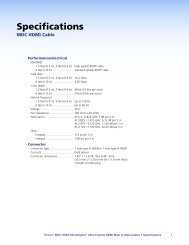
Rear Panel Cabling <strong>and</strong> Features<br />
Figure 2 shows an <strong>XTP</strong> <strong>CrossPoint</strong> <strong>1600</strong>. Figure 3, on the next page, shows an<br />
<strong>XTP</strong> <strong>CrossPoint</strong> <strong>3200</strong>. The two models have similar features, but different-sized enclosures<br />
<strong>and</strong> a different arrangement of the features.<br />
1<br />
1−4<br />
INPUTS<br />
5−8<br />
9−12<br />
13−16<br />
3<br />
REMOTE<br />
RS-232/RS-422<br />
ACT<br />
LAN<br />
LINK<br />
RESET<br />
4<br />
5<br />
1−4<br />
OUTPUTS<br />
5−8<br />
9−12<br />
13−16<br />
100-240V -- A MAX<br />
50-60Hz<br />
6<br />
2<br />
Figure 2.<br />
<strong>XTP</strong> <strong>CrossPoint</strong> <strong>1600</strong> Matrix Switcher Rear Panel<br />
ATTENTION:<br />
• Use electrostatic discharge (ESD) precautions (be electrically grounded) when<br />
making connections. Electrostatic discharge can damage equipment, even if you<br />
cannot feel, see, or hear it.<br />
• Remove system power before making all connections.<br />
a Input boards space (see page 12)<br />
b Output boards space (see page 14)<br />
c Remote RS-232 / RS-422 port (see page 22)<br />
d LAN connection (Ethernet connector) (see page 22)<br />
e Reset button <strong>and</strong> LED (see page 22)<br />
f Power connector (see page 22)<br />
<strong>XTP</strong> <strong>CrossPoint</strong> <strong>1600</strong> <strong>and</strong> <strong>3200</strong> Switchers • Installation 10
LAN<br />
RS 232/RS422<br />
1 2<br />
REMOTE<br />
3<br />
4<br />
ACT<br />
LINK<br />
5<br />
RESET<br />
I<br />
N<br />
P<br />
U<br />
T<br />
S<br />
O<br />
U<br />
T<br />
P<br />
U<br />
T<br />
S<br />
100-240V<br />
--A MAX<br />
6<br />
50-60Hz<br />
DISCONNECT POWER<br />
CORD BEFORE<br />
SERVICING<br />
Figure 3.<br />
<strong>XTP</strong> <strong>CrossPoint</strong> <strong>3200</strong> Matrix Switcher Rear Panel<br />
a Input boards space (see page 12)<br />
b Output boards space (see page 14)<br />
c Remote RS-232 / RS-422 port (see page 22)<br />
d LAN connection (Ethernet connector) (see page 22)<br />
e Reset button <strong>and</strong> LED (see page 22)<br />
f Power connector (see page 22)<br />
<strong>XTP</strong> <strong>CrossPoint</strong> <strong>1600</strong> <strong>and</strong> <strong>3200</strong> Switchers • Installation 11
Input <strong>and</strong> Output Boards<br />
On the <strong>XTP</strong> <strong>CrossPoint</strong> <strong>1600</strong>, the top slots are for input boards <strong>and</strong> the bottom slots are<br />
for output boards. On the <strong>XTP</strong> <strong>CrossPoint</strong> <strong>3200</strong>, slots on the left are for input boards <strong>and</strong><br />
the slots on the right are for output boards. Each board installed in a slot supports up to<br />
four inputs or outputs of the applicable type (see Input <strong>and</strong> Output Boards <strong>and</strong> Signal<br />
Types on page 4, item a, below, <strong>and</strong> item b, on page 14.<br />
Input boards can be installed in any order in the input slot locations. Output boards can<br />
likewise be installed in any order in the output slot locations. You can skip a slot with the<br />
only result being that the inputs or outputs service by that slot location are not present in the<br />
matrix. For example, if you omit installing a board in input slot 3, inputs 9 through 12 are not<br />
present <strong>and</strong> the first connector in input slot 4 remains input 13.<br />
NOTE: Ground pins on the input <strong>and</strong> output boards may be labeled as or . The<br />
wiring <strong>and</strong> function are the same, whichever way your board is labeled.<br />
a Input boards space — Install input boards as desired in input slots 1 through 4<br />
(<strong>XTP</strong> <strong>CrossPoint</strong> <strong>1600</strong>) or input slots 1 through 8 (<strong>XTP</strong> <strong>CrossPoint</strong> <strong>3200</strong>) <strong>and</strong> make<br />
connections. See Installing the Input or Output Board or Blank Panel on<br />
page 136 <strong>and</strong> the individual board descriptions below.<br />
NOTE: Install blank panels in unused locations to ensure proper ventilation.<br />
<strong>XTP</strong> CP 4i (<strong>XTP</strong> Input board) — See figure 4.<br />
1a<br />
1c<br />
1a 1c 1a 1c 1a 1c<br />
IN<br />
PWR<br />
SIG<br />
LINK<br />
PWR<br />
SIG<br />
LINK<br />
PWR<br />
SIG<br />
LINK<br />
PWR<br />
SIG<br />
LINK<br />
RS-232<br />
IR<br />
IR/RS-232 OVER <strong>XTP</strong><br />
RS-232 IR RS-232<br />
IR<br />
RS-232<br />
IR<br />
IN<br />
<strong>XTP</strong> CP 4i<br />
<strong>XTP</strong><br />
ACT<br />
LAN LINK<br />
<strong>XTP</strong><br />
ACT<br />
LAN LINK<br />
<strong>XTP</strong><br />
ACT<br />
LAN LINK<br />
<strong>XTP</strong><br />
ACT<br />
LAN LINK<br />
Tx Rx G Tx Rx Tx Rx G Tx Rx Tx Rx G Tx Rx Tx Rx G Tx Rx<br />
1b<br />
1b<br />
1b<br />
1b<br />
1d<br />
Figure 4.<br />
<strong>XTP</strong> Input Board Connectors <strong>and</strong> Indicators<br />
ATTENTION: The <strong>XTP</strong> input board can provide power over <strong>XTP</strong> (PoX) to<br />
connected devices. PoX is intended for indoors use only. No part of a network that<br />
uses PoX can be routed outdoors.<br />
NOTE: PoX must be enabled using:<br />
• SIS comm<strong>and</strong>s (see the applicable <strong>XTP</strong> Power SIS comm<strong>and</strong>s on page 85)<br />
• Built-in HMTL pages (see <strong>XTP</strong> Power Page, on page 132)<br />
• The <strong>XTP</strong> System Configuration software (see the <strong>XTP</strong> System Configuration<br />
Software Guide, available at www.extron.com)<br />
1a<br />
<strong>XTP</strong> input connectors — Connect a TP cable between a compatible <strong>Extron</strong><br />
<strong>XTP</strong> transmitter <strong>and</strong> this connector. See TP connectors on page 16 to wire the<br />
connector.<br />
1b<br />
<strong>XTP</strong> Power indicators — Light to indicate that the input board is providing<br />
power over internet (PoX) to the transmitter connected to this RJ-45 connector.<br />
1c<br />
LAN (Ethernet) connectors — As desired, connect a TP cable between a<br />
host device or control LAN <strong>and</strong> this connector for passive extension to the LAN<br />
(Ethernet) connector on the connected endpoint. See TP connectors on page 16<br />
to wire the connector.<br />
<strong>XTP</strong> <strong>CrossPoint</strong> <strong>1600</strong> <strong>and</strong> <strong>3200</strong> Switchers • Installation 12
1d<br />
IR/RS-232 Over <strong>XTP</strong> Connectors — If desired, connect serial RS-232 signals,<br />
modulated IR signals, or both to these 3.5 mm, 5-pole captive screw connectors<br />
for bidirectional RS-232 <strong>and</strong> IR communications on the associated inputs. See<br />
RS-232 <strong>and</strong> IR connectors on page 18 to wire the connectors.<br />
<strong>XTP</strong> CP 4i HDMI (HDMI Input board) — See figure 5.<br />
IN<br />
AUDIO<br />
L R L R L R L R<br />
<strong>XTP</strong> CP 4i HDMI<br />
IN<br />
1e<br />
1e<br />
1e<br />
1e<br />
1f<br />
Figure 5.<br />
HDMI Input Board Connectors<br />
1e<br />
Input connector — Connect an HDMI cable between this port <strong>and</strong> the HDMI<br />
output port of the digital video source. See HDMI connectors on page 18 for<br />
pin assignments <strong>and</strong> to use the LockIt HDMI Cable Lacing Bracket to secure the<br />
connector to the transmitter.<br />
1f<br />
Audio Inputs (analog audio) connectors — Connect balanced or<br />
unbalanced stereo audio inputs to these 3.5 mm, 5-pole captive screw<br />
connectors. See Analog audio input connectors on page 20 to<br />
wire the connectors.<br />
<strong>XTP</strong> CP 4i DVI Pro (DVI Pro Input board) — See figure 6.<br />
IN<br />
AUDIO<br />
L R L R L R L R<br />
<strong>XTP</strong> CP 4i DVI Pro<br />
IN<br />
1g<br />
1g<br />
1g<br />
1g<br />
1h<br />
Figure 6.<br />
DVI Pro Input Board Connectors<br />
NOTE: Although the DVI Pro boards use DVI-I connectors, the switchers h<strong>and</strong>le<br />
only DVI-D (digital) video.<br />
1g<br />
Input connector — Connect a DVI cable between this port <strong>and</strong> the DVI<br />
output port of the digital video source. See DVI connectors on page 19 for pin<br />
assignments.<br />
1h<br />
Audio Inputs (analog audio) connectors — Connect balanced<br />
or unbalanced stereo audio inputs to these 3.5 mm, 5-pole captive<br />
screw connectors. See Analog audio input connectors on page 20<br />
to wire the connectors.<br />
<strong>XTP</strong> CP 4i VGA (VGA Input board) — See figure 7.<br />
IN<br />
AUDIO<br />
L R L R L R L R<br />
<strong>XTP</strong> CP 4i VGA<br />
IN<br />
1i<br />
1i<br />
1i<br />
1i<br />
1j<br />
Figure 7.<br />
VGA Input Board Connectors<br />
1i<br />
Input connector — Connect a VGA cable between this port <strong>and</strong> the analog<br />
video output port of the digital video source. See Analog video connectors on<br />
page 20 for pin assignments <strong>and</strong> non-RGB video formats.<br />
1j<br />
Audio Inputs (analog audio) connectors — Connect balanced<br />
or unbalanced stereo audio inputs to these 3.5 mm, 5-pole captive<br />
screw connectors. See Analog audio input connectors on page 20<br />
to wire the connectors.<br />
<strong>XTP</strong> <strong>CrossPoint</strong> <strong>1600</strong> <strong>and</strong> <strong>3200</strong> Switchers • Installation 13
Output boards space — Install output boards as desired in input slots 1 through 4<br />
(<strong>XTP</strong> <strong>CrossPoint</strong> <strong>1600</strong>) or input slots 1 through 8 (<strong>XTP</strong> <strong>CrossPoint</strong> <strong>3200</strong>) <strong>and</strong> make<br />
connections. See Installing the Input or Output Board or Blank Panel on<br />
page 136 <strong>and</strong> the individual board descriptions below.<br />
NOTE: Install blank panels in unused locations to ensure proper ventilation.<br />
<strong>XTP</strong> CP 4o (<strong>XTP</strong> Output board) — See figure 8.<br />
2a<br />
2c<br />
2a 2c 2a 2c 2a 2c<br />
OUT<br />
SIG LINK<br />
PWR<br />
<strong>XTP</strong><br />
ACT<br />
LAN LINK<br />
SIG LINK<br />
PWR<br />
<strong>XTP</strong><br />
ACT<br />
LAN LINK<br />
SIG LINK<br />
PWR<br />
<strong>XTP</strong><br />
ACT<br />
LAN LINK<br />
SIG LINK<br />
PWR<br />
<strong>XTP</strong><br />
ACT<br />
LAN LINK<br />
IR/RS-232 OVER <strong>XTP</strong><br />
RS-232 IR RS-232 IR RS-232 IR RS-232 IR<br />
Tx Rx G Tx Rx Tx Rx G Tx Rx Tx Rx G Tx Rx Tx Rx G<br />
Tx Rx<br />
OUT<br />
<strong>XTP</strong> CP 4o<br />
2b<br />
2b<br />
2b<br />
2b<br />
2d<br />
Figure 8.<br />
<strong>XTP</strong> Output Board Connectors <strong>and</strong> Indicators<br />
ATTENTION: The <strong>XTP</strong> output board can provide PoX to connected devices. PoX<br />
is intended for indoors use only. No part of a network that uses PoX can be routed<br />
outdoors.<br />
NOTE: PoX must be enabled using:<br />
• SIS comm<strong>and</strong>s (see the applicable <strong>XTP</strong> Power SIS comm<strong>and</strong>s on page 85)<br />
• Built-in HMTL pages (see <strong>XTP</strong> Power Page, on page 132)<br />
• The <strong>XTP</strong> System Configuration software (see the <strong>XTP</strong> System Configuration<br />
Software Guide, available at www.extron.com)<br />
2a<br />
<strong>XTP</strong> output connectors — Connect a TP cable between this connector <strong>and</strong><br />
a compatible <strong>Extron</strong> <strong>XTP</strong> receiver. See TP connectors on page 16 to wire the<br />
connector.<br />
2b<br />
<strong>XTP</strong> Power indicators — Lights to indicate that the output board is providing<br />
power over internet (PoX) to the receiver connected to this RJ-45 connector.<br />
2c<br />
LAN (Ethernet) connectors — As desired, connect a TP cable between a<br />
host device or control LAN <strong>and</strong> this connector for passive extension to the LAN<br />
(Ethernet) connector on the connected endpoint. See TP connectors on page 16<br />
to wire the connector.<br />
2d<br />
IR/RS-232 Over <strong>XTP</strong> Connectors — If desired, connect serial RS-232 signals,<br />
modulated IR signals, or both to these 3.5 mm, 5-pole captive screw connectors<br />
for bidirectional RS-232 <strong>and</strong> IR communications on the associated outputs. See<br />
RS-232 <strong>and</strong> IR connectors on page 18 to wire the connectors.<br />
<strong>XTP</strong> <strong>CrossPoint</strong> <strong>1600</strong> <strong>and</strong> <strong>3200</strong> Switchers • Installation 14
<strong>XTP</strong> CP 4o HDMI (HDMI Output board) — See figure 9.<br />
OUT<br />
AUDIO<br />
<strong>XTP</strong> CP 4o HDMI<br />
L R L R L R L R<br />
OUT<br />
2e<br />
2e<br />
2e<br />
2e<br />
2f<br />
Figure 9.<br />
HDMI Output Board Connectors<br />
2e<br />
Input connector — Connect an HDMI cable between this port <strong>and</strong> an HDMI<br />
video display. See HDMI connectors on page 18 for pin assignments <strong>and</strong> to use<br />
the LockIt HDMI Cable Lacing Bracket to secure the connector to the transmitter.<br />
2f<br />
Audio Outputs (analog audio) connectors — Connect audio<br />
devices such as an audio amplifier or powered speakers, to these<br />
3.5 mm, 5-pole captive screw connectors. These connectors output<br />
unamplified, level audio, whether it is tied from an analog analog input<br />
or de-embedded from a digital input. See Analog audio output connectors on<br />
page 21 to wire the connectors.<br />
<strong>XTP</strong> CP 4o DVI Pro (DVI Pro Output board) — See figure 10.<br />
OUT<br />
AUDIO<br />
L R L R L R L R<br />
<strong>XTP</strong> CP 4o DVI Pro<br />
OUT<br />
2g<br />
2g<br />
2g<br />
2g<br />
2h<br />
Figure 10.<br />
DVI Pro Output Board Connectors<br />
NOTE: Although the DVI Pro boards use DVI-I connectors, the switchers h<strong>and</strong>le<br />
only DVI-D (digital) video.<br />
2g<br />
Input connector — Connect a DVI cable between this port <strong>and</strong> an DVI video<br />
display. See DVI connectors on page 19 for pin assignments.<br />
2h<br />
Audio Outputs (analog audio) connectors — Connect audio<br />
devices such as an audio amplifier or powered speakers, to these<br />
3.5 mm, 5-pole captive screw connectors. These connectors output<br />
unamplified, level audio, whether it is tied from an analog analog input<br />
or de-embedded from a digital input. See Analog audio output connectors on<br />
page 21 to wire the connectors.<br />
<strong>XTP</strong> CP 4o SA (Analog Audio Output board) — See figure 11.<br />
OUT<br />
AUDIO<br />
L R L R L R L R<br />
<strong>XTP</strong> CP 4o SA<br />
OUT<br />
2i<br />
Figure 11.<br />
Analog Audio Board Connectors<br />
2i<br />
Audio Outputs (analog audio) connectors — Connect audio<br />
devices such as an audio amplifier or powered speakers, to these<br />
3.5 mm, 5-pole captive screw connectors. These connectors output<br />
unamplified, level audio, whether it is tied from an analog analog input<br />
or de-embedded from a digital input. See Analog audio output connectors on<br />
page 21 to wire the connectors.<br />
<strong>XTP</strong> <strong>CrossPoint</strong> <strong>1600</strong> <strong>and</strong> <strong>3200</strong> Switchers • Installation 15
Input <strong>and</strong> output pin assignments <strong>and</strong> wiring<br />
TP connectors<br />
It is essential that your cables (on the <strong>XTP</strong> <strong>and</strong> LAN [Ethernet] connectors) be the correct<br />
type <strong>and</strong> that they be properly terminated with the correct pinout. These links use<br />
unshielded twisted pair (UTP) or shielded twisted pair (STP) cables, terminated with RJ-45<br />
connectors. <strong>XTP</strong> <strong>and</strong> LAN cables are limited to a length of 330 feet (100 m).<br />
NOTES:<br />
• Do not use st<strong>and</strong>ard telephone cables. Telephone cables do not support Ethernet<br />
or Fast Ethernet.<br />
• Do not stretch or bend cables. Transmission errors can occur.<br />
The cable used depends on your network speed. The switcher LAN port supports both<br />
10 Mbps (10Base-T — Ethernet) <strong>and</strong> 100 Mbps (100Base-T — Fast Ethernet), half-duplex<br />
<strong>and</strong> full-duplex Ethernet connections. Input <strong>and</strong> output boards support 100Base-T only.<br />
• 10Base-T Ethernet requires CAT 3 UTP or STP cable at minimum.<br />
• 100Base-T Fast Ethernet requires CAT 5e UTP or STP cable at minimum.<br />
The TP cable can be terminated as a straight-through cable or a crossover cable <strong>and</strong> must<br />
be properly terminated for your application (see figure 12).<br />
• Crossover cable — Direct connection between the computer <strong>and</strong> the <strong>XTP</strong> matrix<br />
switcher<br />
• Patch (straight) cable — Connection of the <strong>XTP</strong> matrix switcher to an Ethernet LAN<br />
<strong>and</strong> connection to the input <strong>and</strong> output board <strong>XTP</strong> connectors.<br />
Crossover Cable<br />
Straight-through Cable<br />
Pins: LAN Port <strong>XTP</strong> Ports <strong>and</strong> LAN Port<br />
12345678<br />
Insert Twisted<br />
Pair Wires<br />
RJ-45<br />
Connector<br />
Figure 12.<br />
End 1 End 2 End 1 End 2<br />
Pin<br />
1<br />
2<br />
3<br />
4<br />
5<br />
6<br />
7<br />
8<br />
Wire color<br />
White-green<br />
Green<br />
White-orange<br />
Blue<br />
White-blue<br />
Orange<br />
White-brown<br />
Brown<br />
Wire color<br />
White-orange<br />
Orange<br />
White-green<br />
Blue<br />
White-blue<br />
Green<br />
White-brown<br />
Brown<br />
Pin<br />
1<br />
2<br />
3<br />
4<br />
5<br />
6<br />
7<br />
8<br />
Wire color<br />
White-orange<br />
Orange<br />
White-green<br />
Blue<br />
White-blue<br />
Green<br />
White-brown<br />
Brown<br />
Wire color<br />
White-orange<br />
Orange<br />
White-green<br />
Blue<br />
White-blue<br />
Green<br />
White-brown<br />
Brown<br />
T568A<br />
T568B<br />
A cable that is wired as T568A at one end<br />
<strong>and</strong> T568B at the other (Tx <strong>and</strong> Rx pairs<br />
reversed) is a "crossover" cable.<br />
RJ-45 Connector <strong>and</strong> Pinout Tables<br />
T568B<br />
T568B<br />
A cable that is wired the same at both ends is<br />
called a "straight-through" cable, because<br />
no pin/pair assignments are swapped.<br />
Switcher <strong>and</strong> <strong>XTP</strong> board LAN ports —<br />
The LAN ports require CAT 3, CAT 5e, or CAT 6a, crossover or patch cables.<br />
<strong>XTP</strong> <strong>CrossPoint</strong> <strong>1600</strong> <strong>and</strong> <strong>3200</strong> Switchers • Installation 16
<strong>XTP</strong> board <strong>XTP</strong> ports —<br />
The <strong>XTP</strong> input boards <strong>and</strong> output boards are compatible with <strong>Extron</strong> <strong>XTP</strong> DTP 24 SF/UTP<br />
cables, as well as CAT 5e, 6, 6a, <strong>and</strong> 7 shielded twisted pair (F/UTP, SF/UTP, <strong>and</strong> S/FTP)<br />
<strong>and</strong> unshielded twisted pair (U/UTP) cable.<br />
ATTENTION:<br />
• Do not connect these boards to a computer data or telecommunications network.<br />
• Do not use <strong>Extron</strong> UTP23SF-4 Enhanced Skew-Free AV UTP cable or STP201<br />
cable to link the <strong>XTP</strong> products.<br />
• To ensure FCC Class A <strong>and</strong> CE compliance, STP cables <strong>and</strong> STP connectors are<br />
required.<br />
<strong>Extron</strong> recommends using the following practices to achieve full transmission distances up<br />
to 330 feet (100 m) <strong>and</strong> reduce transmission errors.<br />
• Use the following <strong>Extron</strong> <strong>XTP</strong> DTP 24 SF/UTP cables <strong>and</strong> connectors for the best<br />
performance:<br />
• <strong>XTP</strong> DTP 24/1000 Non-Plenum 1000' (305 m) spool 22-236-03<br />
• <strong>XTP</strong> DTP 24P/1000 Plenum 1000' (305 m) spool 22-235-03<br />
• <strong>XTP</strong> DTP 24 Plug Package of 10 101-005-02<br />
• If not using <strong>XTP</strong> DTP 24 cable, at a minimum, <strong>Extron</strong> recommends 24 AWG, solid<br />
conductor, STP cable with a minimum b<strong>and</strong>width of 400 MHz.<br />
• Terminate cables with shielded connectors to the TIA/EIA T 568 B st<strong>and</strong>ard only (patch<br />
cables, see figure 12 on the previous page).<br />
• Limit the use of more than two pass-through points, which may include patch points,<br />
punch down connectors, couplers, <strong>and</strong> power injectors. If these pass-through points<br />
are required, use CAT 6 or 6a shielded couplers <strong>and</strong> punch down connectors.<br />
NOTE: When using cable in bundles or conduits, consider the following:<br />
• Do not exceed 40% fill capacity in conduits.<br />
• Do not comb the cable for the first 20 m, where cables are straightened, aligned,<br />
<strong>and</strong> secured in tight bundles.<br />
• Loosely place cables <strong>and</strong> limit the use of tie wraps or hook <strong>and</strong> loop fasteners.<br />
• Separate twisted pair cables from AC power cables.<br />
<strong>XTP</strong> <strong>CrossPoint</strong> <strong>1600</strong> <strong>and</strong> <strong>3200</strong> Switchers • Installation 17
RS-232 <strong>and</strong> IR connectors<br />
Figure 13 shows how to wire the RS-232 <strong>and</strong> IR connector.<br />
Tx/Rx<br />
Pins<br />
IR Device<br />
Rx Tx Gnd<br />
RS-232 IR<br />
Tx Rx G Tx Rx<br />
Tx Rx Gnd<br />
RS-232 Device<br />
Figure 13. RS-232 <strong>and</strong> IR Connector Wiring<br />
NOTES:<br />
• The length of exposed wires is critical. The ideal length is 3/16 inch (5 mm).<br />
• If the stripped section of wire is longer than 3/16 inch, the exposed wires may<br />
touch, causing a short circuit.<br />
• If the stripped section of wire is shorter than 3/16 inch, wires can be easily<br />
pulled out even if tightly fastened by the captive screws.<br />
• Do not tin the power supply leads before installing them in the connector. Tinned<br />
wires are not as secure in the connector <strong>and</strong> could be pulled out.<br />
HDMI connectors<br />
Figure 14 defines the pinout for the HDMI protocol.<br />
19 1<br />
1 19<br />
18 2<br />
HDMI<br />
Type A Receptacle<br />
2 18<br />
HDMI<br />
Type A Plug<br />
Pin<br />
Signal<br />
Pin<br />
Signal<br />
Pin<br />
Signal<br />
1 TMDS data 2+<br />
7 TMDS data 0+ 13<br />
CEC control<br />
2<br />
TMDS data 2<br />
shield<br />
8<br />
TMDS data 0<br />
shield<br />
Reserved<br />
(NC)<br />
3 TMDS data 2- 9 TMDS data 0- 15 SCL<br />
14<br />
4 TMDS data 1+ 10 TMDS clock+ 16<br />
SDA<br />
5<br />
6<br />
TMDS data 1<br />
shield<br />
TMDS data 1-<br />
11 TMDS clock 17<br />
shield<br />
12 TMDS clock- 18<br />
DDC / CEC<br />
Ground<br />
+5 V power<br />
19<br />
Hot plug detect<br />
Figure 14. HDMI Connector<br />
<strong>XTP</strong> <strong>CrossPoint</strong> <strong>1600</strong> <strong>and</strong> <strong>3200</strong> Switchers • Installation 18
Use the LockIt Lacing Brackets, supplied with the input or output board, to securely fasten<br />
HDMI cables to devices as follows:<br />
1. Plug the HDMI cable into the panel connection (see a in figure 15).<br />
3<br />
4<br />
3<br />
1<br />
2<br />
5<br />
Figure 15.<br />
Installing the LockIt Lacing Bracket<br />
2. Loosen the HDMI connection mounting screw from the panel enough to allow the<br />
LockIt lacing bracket to be placed over it (b). The screw does not have to be removed.<br />
3. Place the LockIt lacing bracket on the screw <strong>and</strong> against the HDMI connector, then<br />
tighten the screw to secure the bracket (c).<br />
ATTENTION: Do not overtighten the HDMI connector mounting screw. The shield<br />
to which it fastens is very thin <strong>and</strong> can easily be stripped.<br />
4. Loosely place the included tie wrap around the HDMI connector <strong>and</strong> the LockIt lacing<br />
bracket as shown (d).<br />
5. While holding the connector securely against the lacing bracket, use pliers or similar<br />
tools to tighten the tie wrap, then remove any excess length (e).<br />
DVI connectors<br />
Figure 14 defines the pinout for the DVI protocol.<br />
9<br />
1<br />
C5<br />
17 24 C3 C4<br />
Female Connector<br />
Male Connector (cable)<br />
* CEC control on pin 8<br />
is a proprietary usage,<br />
not the industry<br />
st<strong>and</strong>ard.<br />
Figure 16.<br />
8<br />
C1<br />
C2<br />
Pin<br />
DVI Connectors<br />
Signal<br />
Pin<br />
Signal<br />
Pin<br />
1<br />
2<br />
TMDS data 2–<br />
TMDS data 2+<br />
9<br />
10<br />
TMDS data 1–<br />
TMDS data 1+<br />
17<br />
18<br />
3<br />
TMDS data 2 TMDS data 1<br />
11<br />
shield<br />
shield<br />
19<br />
4 Spare 12 Spare 20<br />
5 Spare 13 Spare 21<br />
6 DDC clock 14 +5 V power 22<br />
7 DDC data 15 Ground 23<br />
8 CEC control* 16 Hot Plug Detect 24<br />
Signal<br />
TMDS data 0–<br />
TMDS data 0+<br />
TMDS data 0<br />
shield<br />
Spare<br />
Spare<br />
TMDS clock<br />
Shield<br />
TMDS clock+<br />
TMDS clock–<br />
<strong>XTP</strong> <strong>CrossPoint</strong> <strong>1600</strong> <strong>and</strong> <strong>3200</strong> Switchers • Installation 19
5<br />
Analog video connectors<br />
The 15-pin HD (VGA) universal analog input ports accept RGB (RGBHV, RGBs, RGsB), HDTV,<br />
component video (bi- or tri-level sync), S-video, or composite video signals, <strong>and</strong> support<br />
EDID emulation. Figure 17 shows the pinouts for each format type on the connector.<br />
15<br />
1<br />
11<br />
Pin<br />
RGBHV<br />
RGBs<br />
Component<br />
S-video<br />
1<br />
2<br />
Red<br />
Green<br />
Red<br />
Green<br />
R-Y<br />
Y<br />
NC<br />
Luma (Y)<br />
NC<br />
Video<br />
3 Blue Blue B-Y Chroma (C) NC<br />
4 NC<br />
NC<br />
NC NC NC<br />
5 NC<br />
NC<br />
NC NC NC<br />
6 Red return Red return R-Y return NC<br />
7 Green return Green return Y return Luma return<br />
8 Blue return Blue return B-Y NC<br />
9 NC<br />
NC<br />
NC NC<br />
10 Ground Ground NC NC<br />
11 NC<br />
NC<br />
NC NC<br />
12 EDIC/DDC EDID/DDC NC NC<br />
13 H sync C sync<br />
NC NC<br />
14 V sync<br />
NC<br />
NC NC<br />
15 EDID/DDC return EDID/DDC return NC NC<br />
Composite<br />
NC<br />
Video return<br />
NC<br />
NC<br />
NC<br />
NC<br />
NC<br />
NC<br />
NC<br />
NC<br />
Figure 17.<br />
VGA Connectors<br />
Analog audio input connectors<br />
Connectors are included with each switcher, but you must supply the audio cable.<br />
See figure 18 to wire a connector for the appropriate input type. Use the supplied tie-wrap<br />
to strap the audio cable to the extended tail of the connector. High impedance is generally<br />
over 800 ohms.<br />
Do not tin the wires!<br />
Tip<br />
Sleeve<br />
Tip<br />
Sleeve<br />
Unbalanced Stereo Input<br />
L R<br />
Tip<br />
Ring<br />
Sleeves<br />
Tip<br />
Ring<br />
Balanced Stereo Input<br />
Figure 18. Captive Screw Connector Wiring for Audio Inputs<br />
L R<br />
NOTE: The length of exposed wires is important. The ideal length is 3/16 inch (5 mm).<br />
See the NOTES on page 18 for details.<br />
A mono audio connector consists of a tip <strong>and</strong> sleeve. A stereo audio connector consists of<br />
a tip, ring <strong>and</strong> sleeve. See figure 19 to identify the tip, ring, <strong>and</strong> sleeve parts of the connector<br />
when you are making connections for the switcher from existing audio cables. The ring, tip,<br />
<strong>and</strong> sleeve wires are also shown on the captive screw audio connector diagrams, figure 18,<br />
above, <strong>and</strong> figure 20, on the next page.<br />
Tip (+)<br />
Tip (+)<br />
Ring (-)<br />
Sleeve ( ) Sleeve ( )<br />
RCA Connector<br />
3.5 mm Stereo Plug Connector<br />
(balanced)<br />
Figure 19. Typical Audio Connectors<br />
<strong>XTP</strong> <strong>CrossPoint</strong> <strong>1600</strong> <strong>and</strong> <strong>3200</strong> Switchers • Installation 20
The level for each analog audio input can be individually set via the front panel or remote<br />
control to ensure that the level on the output does not vary from input to input (see<br />
Viewing <strong>and</strong> Adjusting the Input Audio Level on page 45). You can also use an SIS<br />
comm<strong>and</strong> (see page 83), the <strong>XTP</strong> System Configuration software (see the <strong>XTP</strong> System<br />
Configuration Software Guide, available at www.extron.com), or the HTML pages (see<br />
Changing the input gain <strong>and</strong> attenuation on page 128).<br />
Analog audio output connectors<br />
Connect audio devices, such as an audio amplifier or powered speakers, to these 3.5 mm,<br />
5-pole captive screw connectors. These connectors output the tied unamplified, line level<br />
audio. See figure 20 to wire an output connector. Use the supplied tie-wrap to strap the<br />
audio cable to the extended tail of the connector.<br />
Do not tin the wires!<br />
NO GROUND HERE<br />
Tip<br />
Sleeves<br />
Tip<br />
NO GROUND HERE<br />
Unbalanced Stereo Output<br />
L R<br />
Tip<br />
Ring<br />
Tip<br />
Ring<br />
Balanced Stereo Output<br />
Figure 20. Captive Screw Connector Wiring for Audio Outputs<br />
ATTENTION: For unbalanced audio, connect the sleeves to the ground contact.<br />
DO NOT connect the sleeves to the negative (-) contacts.<br />
NOTES:<br />
• The length of exposed wires is important. The ideal length is 3/16 inch (5 mm). See<br />
the NOTES on page 18 for details.<br />
• The audio that is output on these connectors is converted from the tied embedded<br />
input signal or the analog audio input. This feature allows you to duplicate the<br />
outputs while eliminating the need for extra receivers.<br />
The volume level for each analog output can be individually set via the front panel or remote<br />
control (see the Viewing <strong>and</strong> Adjusting the Analog Output Volume on page 51). You<br />
can also use an SIS comm<strong>and</strong> (see page 96), the <strong>XTP</strong> System Configuration software<br />
(see the <strong>XTP</strong> System Configuration Software Guide, available at www.extron.com), or the<br />
HTML pages (see Changing the output volume level on page 130).<br />
By default, the audio ties follow the video ties. Audio breakaway, which can be activated<br />
via the front panel or under remote control, allows you to select from any one of the<br />
audio input sources <strong>and</strong> route it separately from its corresponding video source (see<br />
Example 3: Remove a tie from a set of ties on page 35). You can also use an<br />
SIS comm<strong>and</strong> (see page 79), the <strong>XTP</strong> System Configuration software (see the <strong>XTP</strong> System<br />
Configuration Software Guide, available at www.extron.com), or the HTML pages (see<br />
Set <strong>and</strong> View Ties Page on page 126).<br />
L R<br />
<strong>XTP</strong> <strong>CrossPoint</strong> <strong>1600</strong> <strong>and</strong> <strong>3200</strong> Switchers • Installation 21
Remote Control Ports<br />
c Remote RS-232/RS-422 port (see figure 2 on page 10 <strong>and</strong> figure 3 on page 11) —<br />
Connect a host device, such as a computer or touchpanel control to the switcher via<br />
this 9-pin D connector for serial RS-232/RS-422 control (see figure 21).<br />
REMOTE<br />
RS 232/RS422<br />
9<br />
6<br />
5<br />
1<br />
Figure 21.<br />
Pin RS-232 Function<br />
1<br />
2<br />
3<br />
4<br />
5<br />
6<br />
7<br />
8<br />
9<br />
—<br />
TX<br />
RX<br />
—<br />
Gnd<br />
—<br />
—<br />
—<br />
—<br />
Not used<br />
Transmit data<br />
Receive data<br />
Not used<br />
Signal ground<br />
Not used<br />
Not used<br />
Not used<br />
Not used<br />
RS-422 Function<br />
— Not used<br />
TX– Transmit data (–)<br />
RX– Receive data (–)<br />
— Not used<br />
Gnd Signal ground<br />
— Not used<br />
RX+ Receive data (+)<br />
TX+ Transmit data (+)<br />
— Not used<br />
Remote RS-232/RS-422 Port<br />
See the Programming Guide section, beginning on page 69, for definitions of the SIS<br />
comm<strong>and</strong>s (serial comm<strong>and</strong>s to control the switcher <strong>and</strong> connected endpoints via this<br />
connector.<br />
NOTE: The switcher can support either the RS-232 or RS-422 serial<br />
communication protocol, <strong>and</strong> can operate at 9600, 19200, 38400, or 115200<br />
baud rates.<br />
See Selecting the Rear Panel Remote Port Protocol <strong>and</strong> Baud Rate on<br />
page 58 to configure the RS-232/RS-422 port from the front panel.<br />
If desired, connect an MKP 2000 or MKP 3000 remote control panel to the rear panel<br />
Remote port on the switcher. Refer to the MKP 2000 Remote Control Panel User Guide<br />
or the MKP 3000 User Guide for details.<br />
Ethernet Connection<br />
d LAN port (see figure 2 <strong>and</strong> figure 3) — If desired, for IP control of the<br />
system, connect the matrix switcher to a PC or to an Ethernet LAN via this<br />
RJ-45 connector. You can use a PC to control the networked switcher with<br />
SIS comm<strong>and</strong>s from anywhere in the world. You can also control the switcher<br />
ACT<br />
LAN<br />
LINK<br />
from a PC that is running the <strong>Extron</strong> <strong>XTP</strong> Configuration Software or has downloaded<br />
HTML pages from the switcher. See TP connectors on page 16 to wire the connector.<br />
Act LED indicator — The Act LED indicates transmission of data packets on the<br />
RJ-45 connector. This LED should flicker as the switcher communicates.<br />
Link LED indicator — The Link LED indicates that the switcher is properly connected<br />
to an Ethernet LAN. This LED should light steadily.<br />
Reset Button <strong>and</strong> LED<br />
e Reset button (see figure 2 <strong>and</strong> figure 3) — The Reset button initiates four RESET<br />
levels of reset of the matrix switcher. For four different reset levels, press <strong>and</strong><br />
hold the button while the switcher is running or while you power up the<br />
switcher (see Rear Panel Operations on page 60 for details).<br />
Power<br />
f AC power connector (see figure 2 <strong>and</strong> figure 3) — Plug a st<strong>and</strong>ard IEC power cord<br />
into this connector to connect the switcher to a 100 VAC to 240 VAC, 50-60 Hz power<br />
source.<br />
<strong>XTP</strong> <strong>CrossPoint</strong> <strong>1600</strong> <strong>and</strong> <strong>3200</strong> Switchers • Installation 22
Front Panel Configuration Port <strong>and</strong> Power LEDs<br />
CONTROL<br />
I/O<br />
CONTROL<br />
I/O<br />
CONFIG<br />
AUDIO<br />
VIDEO<br />
ENTER PRESET VIEW ESC<br />
ENTER PRESET VIEW ESC AUDIO<br />
VIDEO<br />
CONFIG<br />
PRIMARY<br />
1 2<br />
REDUNDANT<br />
POWER<br />
1 3<br />
2 4<br />
POWER<br />
<strong>XTP</strong> CROSSPOINT <strong>1600</strong><br />
<strong>XTP</strong> SERIES DIGITAL MATRIX SWITCHER<br />
<strong>XTP</strong> CROSSPOINT <strong>3200</strong><br />
<strong>XTP</strong> SERIES DIGITAL MATRIX SWITCHER<br />
1 2<br />
<strong>XTP</strong> <strong>CrossPoint</strong> <strong>1600</strong><br />
1 2<br />
<strong>XTP</strong> <strong>CrossPoint</strong> <strong>3200</strong><br />
Figure 22. Front Panel Configuration (Config) Port <strong>and</strong> Power LEDs<br />
a Configuration port — This mini USB B port serves a similar communications function<br />
as the rear panel Remote port, but it is easier to access than the rear port after the<br />
matrix switcher has been installed <strong>and</strong> cabled.<br />
NOTE: A front panel Configuration port connection <strong>and</strong> a rear panel Remote<br />
port connection can both be active at the same time. If comm<strong>and</strong>s are sent<br />
simultaneously to both, the comm<strong>and</strong> that reaches the processor first is h<strong>and</strong>led<br />
first.<br />
b Power LEDs —<br />
NOTE: The <strong>XTP</strong> <strong>CrossPoint</strong> <strong>3200</strong> has four power supplies installed. These power<br />
supplies are indicated by the following LEDs:<br />
• LEDs 1 <strong>and</strong> 2 — Indicate the status of the two primary 12 V supplies.<br />
• LED 3 — Indicates the status of the redundant 12 V supply.<br />
• LED 4 — Indicates the status of the 48 V power supply, which provides<br />
PoX.<br />
The <strong>XTP</strong> <strong>CrossPoint</strong> <strong>1600</strong> has two power supplies, which provide 12 V<br />
<strong>and</strong> 48 V in its st<strong>and</strong>ard configuration, with two optional, redundant second<br />
power supplies available. These power supplies are indicated by the<br />
following LEDs:<br />
• Primary LED 1 — Indicates the status from the st<strong>and</strong>ard primary 12 V<br />
supply.<br />
• Redundant LED 1 — Indicates the status of 12 V from the optional<br />
redundant supply.<br />
• Primary LED 2 — Indicates the status from the st<strong>and</strong>ard primary 48 V<br />
supply, which provides PoX.<br />
• Redundant LED 2 — Indicates the status of 48 V from the optional<br />
redundant supply.<br />
Green — Indicates that the associated power supply is operating within normal<br />
tolerances.<br />
Red — Indicates that the associated power supply is operating outside the normal<br />
tolerances or has failed.<br />
<strong>XTP</strong> <strong>CrossPoint</strong> <strong>1600</strong> <strong>and</strong> <strong>3200</strong> Switchers • Installation 23
POWER<br />
Operation<br />
This section describes the front panel operation of the <strong>XTP</strong> <strong>CrossPoint</strong> Matrix Switcher,<br />
including:<br />
• Front Panel Controls <strong>and</strong> Indicators<br />
• Front Panel Operations<br />
• Rear Panel Operations<br />
• Optimizing the Analog Audio<br />
• Troubleshooting<br />
• Configuration Worksheets<br />
Front Panel Controls <strong>and</strong> Indicators<br />
The front panel controls (see figure 23 <strong>and</strong> figure 24, on the next page) are grouped into<br />
two sets. The input <strong>and</strong> output buttons, a <strong>and</strong> b, are grouped on the left side of the<br />
control panel. The control buttons <strong>and</strong> video/audio (I/O) selection buttons, c through h,<br />
are grouped on the right side of the panel.<br />
3<br />
4<br />
1<br />
INPUTS<br />
1 2 3 4 5 6 7 8 9 10 11 12 13 14 15 16<br />
5<br />
6<br />
2<br />
OUTPUTS<br />
1 2 3 4 5 6 7 8 9 10 11 12 13 14 15 16<br />
CONFIG<br />
CONTROL<br />
ENTER PRESET VIEW ESC<br />
VIDEO<br />
I/O<br />
AUDIO<br />
7<br />
8<br />
PRIMARY<br />
1 2<br />
REDUNDANT<br />
9<br />
POWER<br />
1 2<br />
1 2<br />
<strong>XTP</strong> CROSSPOINT <strong>1600</strong><br />
<strong>XTP</strong> SERIES DIGITAL MATRIX SWITCHER<br />
Figure 23. Front Panel, <strong>XTP</strong> <strong>CrossPoint</strong> <strong>1600</strong> Switcher<br />
a Input buttons (see page 26)<br />
b Output buttons (see page 26)<br />
c Enter button (see page 27)<br />
d Preset button (see page 27)<br />
e View button (see page 28)<br />
f Esc button (see page 28)<br />
g Video button (see page 29)<br />
h Audio button (see page 29)<br />
i Power LEDs (see page 29)<br />
<strong>XTP</strong> <strong>CrossPoint</strong> <strong>1600</strong> <strong>and</strong> <strong>3200</strong> Switchers • Operation 24
<strong>XTP</strong> CROSSPOINT <strong>3200</strong><br />
1<br />
2<br />
INPUTS<br />
1 2 3 4 5 6 7 8 9 10 11 12 13 14 15 16<br />
17 18 19 20 21 22 23 24 25 26 27 28 29 30 31 32<br />
1 2 3 4 5 6 7 8 9 10 11 12 13 14 15 16<br />
17 18 19 20 21 22 23 24 25 26 27 28 29 30 31 32<br />
OUTPUTS<br />
CONTROL<br />
I/O<br />
CONFIG 8<br />
ENTER PRESET VIEW ESC<br />
AUDIO<br />
VIDEO<br />
1 3<br />
2 4<br />
POWER<br />
3<br />
4<br />
5<br />
6<br />
7<br />
9<br />
<strong>XTP</strong> SERIES DIGITAL MATRIX SWITCHER<br />
Figure 24. Front Panel, <strong>XTP</strong> <strong>CrossPoint</strong> <strong>3200</strong><br />
a Input buttons (see page 26)<br />
b Output buttons (see page 26)<br />
c Enter button (see page 27)<br />
d Preset button (see page 27)<br />
e View button (see page 28)<br />
f Esc button (see page 28)<br />
g Video button (see page 29)<br />
h Audio button (see page 29)<br />
i Power LEDs (see page 29)<br />
The illuminated pushbuttons can be labeled with text, graphics, or both. The buttons<br />
can be set to provide amber background illumination all the time, or the background<br />
illumination can be turned off (see Background Illumination on page 58). The buttons<br />
blink or are lit at full intensity (depending on the operation) when selected.<br />
<strong>XTP</strong> <strong>CrossPoint</strong> <strong>1600</strong> <strong>and</strong> <strong>3200</strong> Switchers • Operation 25
Input <strong>and</strong> Output Buttons<br />
NOTES:<br />
• Input <strong>and</strong> output buttons cannot select an input or output number that is higher<br />
than your matrix size or if the board that supports it is not installed. Unselectable<br />
buttons do have other functions as described in the following pages.<br />
• See Front Panel Operations, beginning on page 30 for detailed descriptions of<br />
the following operations.<br />
Primary functions<br />
Action<br />
Indication<br />
Select input or output for tie being created.<br />
Blink: potential tie/untie.<br />
Lit: current tie<br />
Amber: video <strong>and</strong> audio tie<br />
Green: video only tie<br />
Red: audio only tie<br />
1 2 3<br />
16<br />
32<br />
through<br />
or<br />
Secondary functions<br />
Presets Action Select a preset in Preset mode.<br />
Indication<br />
Lit: A preset has already been saved to this location.<br />
Blink: Preset location is selected to be saved.<br />
Input audio Action<br />
Input buttons: Select the input for audio gain or attenuation adjustment.<br />
level Indication<br />
Input buttons lit: Input audio selected for adjustment.<br />
Indication Output buttons lit or blinking: Indicate the input gain or attenuation level.<br />
Output Action<br />
Output buttons: Select the output for audio volume adjustment.<br />
audio Indication<br />
Output buttons lit: Output audio is selected for adjustment.<br />
volume<br />
Indication<br />
Input buttons lit or blinking: Indicated the output volume level.<br />
Output Action<br />
Output buttons: Press <strong>and</strong> hold to mute or unmute the output.<br />
mutes Indication<br />
Output buttons blinking: Output is muted.<br />
Background Action Input 1 <strong>and</strong> Input 2 buttons:<br />
illumination<br />
Toggle between background<br />
illumination or buttons unlit.<br />
a Input buttons — The input buttons have one primary function (❏) <strong>and</strong> three<br />
secondary functions (•):<br />
❏ Select <strong>and</strong> identify an input for creating ties or for audio level adjustment.<br />
• Select a preset.<br />
• Display the output volume level.<br />
• (Input 1 <strong>and</strong> Input 2 only) Toggle background illumination of the buttons on <strong>and</strong> off.<br />
b Output buttons — The output buttons have one primary function (❏) <strong>and</strong> three<br />
secondary functions (•):<br />
❏ Select <strong>and</strong> identify an output for ties or for volume adjustment.<br />
• Select a preset.<br />
• Mute the output.<br />
• Display the audio level of the selected input.<br />
<strong>XTP</strong> <strong>CrossPoint</strong> <strong>1600</strong> <strong>and</strong> <strong>3200</strong> Switchers • Operation 26
Control Buttons<br />
Primary functions<br />
NOTE: See Front Panel Operations, beginning on page 30 for detailed descriptions<br />
of the following operations.<br />
Action Save changes Select Preset mode Select View mode Cancel or Escape<br />
Indication Blink: Save needed Blink: Save preset<br />
Lit: Recall preset<br />
View mode<br />
selected<br />
Flashes once<br />
ENTER PRESET VIEW ESC<br />
Secondary functions<br />
Port<br />
Action 1<br />
Select Configuration mode.<br />
configuration Action 2 Select 9600 baud Select 19200 baud Select 38400 baud Select 115200 baud<br />
Indication Blink: 9600 baud Blink: 19200 baud Blink: 38400 baud Blink: 115200 baud<br />
Front panel<br />
locks<br />
Action1<br />
Select Lock mode 1 or toggle between<br />
mode 2 <strong>and</strong> mode 1.<br />
Action 2 Select Lock mode 2 or toggle between mode 0 <strong>and</strong> mode 2.<br />
Audio Action In Audio mode,<br />
decrease input<br />
level or output<br />
volume.<br />
In Audio mode,<br />
increase input<br />
level or output<br />
volume.<br />
c Enter button — The Enter button has two primary functions (❏) <strong>and</strong> two secondary<br />
functions (•):<br />
❏ Saves configuration or preset changes that you make on the front panel. To create<br />
a simple configuration:<br />
Specify video, audio, or both (see I/O buttons [item g] <strong>and</strong> [item h]).<br />
Press the desired input button (item a).<br />
Press the desired output button or buttons (item b).<br />
Press the Enter button.<br />
❏ Indicates that a potential tie has been created but not saved.<br />
• With the Preset, View, <strong>and</strong> Esc buttons, selects Serial Port Configuration mode.<br />
• Selects 9600 baud for the rear panel Remote port in Serial Port Configuration mode<br />
<strong>and</strong> indicates the selection.<br />
d Preset button — The Preset button has two primary functions (❏) <strong>and</strong> three secondary<br />
functions (•):<br />
❏ Activates Save Preset mode to save a configuration as a preset <strong>and</strong> Recall Preset<br />
mode to activate a previously-defined preset.<br />
❏ Blinks when Save Preset mode is active <strong>and</strong> lights steadily when Recall Preset<br />
mode is active.<br />
• With the Enter, View, <strong>and</strong> Esc buttons, selects Serial Port Configuration mode.<br />
• Selects 19200 baud for the rear panel Remote port in Serial Port Configuration<br />
mode <strong>and</strong> indicates the selection.<br />
• With the Vew <strong>and</strong> Esc buttons, selects front panel security Lock mode 2 or toggles<br />
between mode 0 (unlocked) <strong>and</strong> mode 2.<br />
<strong>XTP</strong> <strong>CrossPoint</strong> <strong>1600</strong> <strong>and</strong> <strong>3200</strong> Switchers • Operation 27
e View () button has two primary functions (❏) <strong>and</strong> six secondary<br />
functions (•):<br />
❏ Cancels operations or selections in progress <strong>and</strong> resets the front panel button<br />
indicators.<br />
❏ Flashes once to indicate that the escape function has been activated.<br />
• Increases the audio level of the selected analog input.<br />
• Increases the volume of the selected analog output.<br />
• With the Enter, Preset, <strong>and</strong> View buttons, selects Serial Port Configuration mode.<br />
• Selects 115200 baud for the rear panel Remote port in Serial Port Configuration<br />
mode <strong>and</strong> indicates the selection.<br />
• With the Preset button <strong>and</strong> View button, selects between front panel locks<br />
(Lock mode 2 <strong>and</strong> Lock mode 0)<br />
• With the View button, selects between front panel locks (Lock mode 2 <strong>and</strong><br />
Lock mode 1).<br />
<strong>XTP</strong> <strong>CrossPoint</strong> <strong>1600</strong> <strong>and</strong> <strong>3200</strong> Switchers • Operation 28
I/O Controls<br />
NOTE: See Front Panel Operations, beginning on page 30 for detailed descriptions<br />
of the following operations.<br />
Primary functions<br />
Action Select video Select audio<br />
Indication Green: selected Red: selected<br />
VIDEO<br />
AUDIO<br />
Secondary functions<br />
Resets Action 1: Perform a system reset.<br />
Port<br />
Action Select RS-232. Select RS-422<br />
Configuration Indication Blink: selected Blink: selected<br />
Audio Action Select Audio mode.<br />
g Video button — The Video button has one primary function (❏) <strong>and</strong> two secondary<br />
functions (•):<br />
❏ Selects <strong>and</strong> deselects video for a configuration that is being created or viewed <strong>and</strong><br />
lights green to indicate that video is available for configuring or for viewing.<br />
• With the Audio button, comm<strong>and</strong>s the front panel system reset.<br />
• Selects the RS-232 protocol for the rear panel Remote port in Serial Port<br />
Configuration mode <strong>and</strong> indicates the selection.<br />
h Audio button — The Audio button has one primary function (❏) <strong>and</strong> three secondary<br />
functions (•):<br />
❏ Selects <strong>and</strong> deselects audio for a configuration that is being created or viewed <strong>and</strong><br />
lights to indicate that audio is available for configuration or viewing.<br />
• Selects the Audio mode, in which you can adjust the analog input audio level <strong>and</strong><br />
the analog output audio volume.<br />
• With the Video button, comm<strong>and</strong>s the front panel system reset.<br />
• Selects the RS-422 protocol for the rear panel Remote port in Serial Port<br />
Configuration mode <strong>and</strong> indicates the selection.<br />
Power LEDs<br />
i Primary <strong>and</strong> Redundant Power Supply LEDs —<br />
NOTE: See item b, on page 23, to identify the power supplies indicated by the<br />
LEDs.<br />
Green — Indicates that the associated power supply is operating within normal<br />
tolerances.<br />
Red — Indicates that the associated power supply is operating outside the normal<br />
tolerances or has failed.<br />
<strong>XTP</strong> <strong>CrossPoint</strong> <strong>1600</strong> <strong>and</strong> <strong>3200</strong> Switchers • Operation 29
Button Icons<br />
The numbered translucent covers on the input <strong>and</strong> output pushbuttons can be removed<br />
<strong>and</strong> replaced to insert labels behind the covers.<br />
Input <strong>and</strong> output labels can be created easily with the <strong>Extron</strong> Button-Label Generator<br />
software, which is shipped with every <strong>Extron</strong> matrix switcher. Each input <strong>and</strong> output can be<br />
labeled with names, alphanumeric characters, or color bitmaps for easy <strong>and</strong> intuitive input<br />
<strong>and</strong> output selection (see figure 25). See the Removing <strong>and</strong> Installing Button Labels,<br />
on page 136, for details on using the labeling software, blank labels you can fill in yourself,<br />
<strong>and</strong> a procedure for removing <strong>and</strong> replacing the translucent covers.<br />
INPUTS<br />
8 9<br />
10 VCR 13 15<br />
Computer<br />
Computer<br />
VTG 200<br />
8 9<br />
DVD<br />
Document<br />
Camera<br />
28 29 30<br />
31 32<br />
Figure 25. Sample Button Icons<br />
Front Panel Operations<br />
The following sections detail the power-up process <strong>and</strong> then provide sample procedures for<br />
the following actions:<br />
• Creating ties, sets of ties, <strong>and</strong> configurations<br />
• Changing a configuration<br />
• Viewing ties, sets of ties, <strong>and</strong> configurations<br />
• Saving a preset<br />
• Recalling a preset<br />
• Muting <strong>and</strong> unmuting outputs<br />
• Viewing <strong>and</strong> Adjusting the Analog Input Audio Level<br />
• Viewing <strong>and</strong> Adjusting the Analog Output Volume<br />
• Locking <strong>and</strong> unlocking the front panel<br />
• Performing front panel resets<br />
• Toggling background illumination on <strong>and</strong> off<br />
• Reading <strong>and</strong> setting the Remote port settings<br />
<strong>XTP</strong> <strong>CrossPoint</strong> <strong>1600</strong> <strong>and</strong> <strong>3200</strong> Switchers • Operation 30
Definitions<br />
The following <strong>Extron</strong> matrix switcher terms are used throughout this guide:<br />
Tie — An input-to-output connection<br />
Set of ties — An input tied to two or more outputs.<br />
NOTE: An output can never be tied to more than one input.<br />
Configuration — One or more ties or one or more sets of ties<br />
Current configuration — The configuration that is currently active in the switcher (also<br />
called configuration 0)<br />
Global memory preset — A configuration that has been stored. Up to 32 global memory<br />
presets can be stored in memory. Preset locations are assigned to the input buttons <strong>and</strong><br />
(where necessary) output buttons. When a preset is retrieved from memory, it becomes the<br />
current configuration.<br />
Power<br />
Apply power by connecting the power cord between the switcher <strong>and</strong> an AC source. The<br />
switcher performs a self-test that flashes the front panel button indicators red, green, <strong>and</strong><br />
amber <strong>and</strong> then turns them off. An error-free power-up self-test sequence leaves all input,<br />
output, <strong>and</strong> control buttons either unlit or showing background illumination <strong>and</strong> the Video<br />
button <strong>and</strong> the Audio button lit.<br />
The current configuration <strong>and</strong> all presets are saved in non-volatile memory. When power is<br />
applied, the most recent configuration is retrieved. The previous presets remain intact.<br />
If an error occurs during the self-test, the switcher locks up <strong>and</strong> does not operate. If your<br />
switcher locks up on power-up, call the <strong>Extron</strong> S3 Sales <strong>and</strong> Technical Support Hotline. See<br />
the end of this guide for the phone number in your region of the world.<br />
Front Panel Security Lockouts<br />
In the procedural descriptions that follow, it is assumed that the switcher is in Lock mode 0<br />
(fully unlocked). The following two Lock modes are also available:<br />
• Lock mode 1 — All changes are locked from the front panel (except for setting Lock<br />
mode 2). Some functions can be viewed.<br />
• Lock mode 2 — Advanced features are locked <strong>and</strong> can be viewed only. Basic functions<br />
are unlocked.<br />
NOTE: The switcher is shipped from the factory in Lock mode 2. See Setting the<br />
Front Panel Locks (Executive Modes) on page 56 for a detailed list of basic <strong>and</strong><br />
advanced functions <strong>and</strong> the procedure to set the various front panel locks.<br />
<strong>XTP</strong> <strong>CrossPoint</strong> <strong>1600</strong> <strong>and</strong> <strong>3200</strong> Switchers • Operation 31
Creating a Configuration<br />
The current configuration can be changed using the front panel buttons. Change the current<br />
configuration as follows:<br />
1. Press the Esc button to clear any input button indicators, output button indicators, or<br />
control button indicators that may be lit.<br />
2. Select video, audio, or both for configuration by pressing the Video button <strong>and</strong> Audio<br />
button as necessary.<br />
3. Select the desired input <strong>and</strong> output(s) by pressing the input <strong>and</strong> output buttons.<br />
• Input buttons <strong>and</strong> output buttons light or blink:<br />
• Amber to indicate video <strong>and</strong> audio ties<br />
• Green to indicate video only ties<br />
• Red to indicate audio only ties<br />
• To indicate potential ties, output buttons blink the appropriate color when an input<br />
is selected.<br />
• To indicate current ties, output buttons light steadily the appropriate color when an<br />
input is selected.<br />
• To clear unwanted outputs, press <strong>and</strong> release the associated lit output buttons. To<br />
indicate potential unties, output buttons blink the appropriate color when an output<br />
is deselected but not untied from the input.<br />
4. Press <strong>and</strong> release the Enter button to accept the tie or to break an existing tie.<br />
5. Repeat steps 1 through 4 to create or clear additional ties until the desired configuration<br />
is complete.<br />
NOTES:<br />
• Only one video input <strong>and</strong> one audio input can be tied to an output.<br />
• If a tie is made between an input <strong>and</strong> an output, <strong>and</strong> the selected output was<br />
previously tied to another input, the older tie is broken in favor of the newer tie.<br />
• If an input with no tie is selected, only the button for the selected input lights.<br />
• When the Video button <strong>and</strong> the Audio button are lit, if an input with an audio<br />
tie but no video tie is selected, the button for the input <strong>and</strong> the button for the<br />
output light the appropriate color (amber, green, or red).<br />
• As each input <strong>and</strong> output is selected, the associated output button blinks<br />
the appropriate color to indicate a tentative tie. Buttons for outputs that were<br />
already tied to the input light the appropriate color steadily. Outputs that are<br />
already tied can be left on, along with new blinking selections, or toggled off by<br />
pressing the associated output button.<br />
<strong>XTP</strong> <strong>CrossPoint</strong> <strong>1600</strong> <strong>and</strong> <strong>3200</strong> Switchers • Operation 32
Example 1: Create a set of video <strong>and</strong> audio ties<br />
1. Clear all selections: Press <strong>and</strong> release the Esc button.<br />
Press the Esc button to clear all selections.<br />
C O N T R O L<br />
ENTER PRESET<br />
VIEW<br />
ESC<br />
The button flashes once.<br />
2. Select video <strong>and</strong> audio for the tie: If necessary, press <strong>and</strong> release the Video button<br />
<strong>and</strong> the Audio button to light both.<br />
I / O<br />
VIDEO<br />
AUDIO<br />
Press the Video button to toggle on <strong>and</strong> off.<br />
The button lights green when selected.<br />
Press the Audio button to toggle on <strong>and</strong> off.<br />
The button lights red when selected.<br />
3. Select an input: Press <strong>and</strong> release the input 5 button.<br />
Press the button.<br />
The button lights amber.<br />
INPUTS<br />
1 2 3 4 5 6 7 8 15 16<br />
4. Select the outputs: Press <strong>and</strong> release the output 3, output 4, <strong>and</strong> output 8 buttons.<br />
Press the buttons.<br />
The buttons blink amber to indicate that the selected video <strong>and</strong> audio inputs<br />
will be tied to these outputs.<br />
OUTPUTS<br />
C O N T R O L<br />
1 2 3 4 5 6 7 8 15 16<br />
ENTER PRESET<br />
VIEW<br />
ESC<br />
The Enter button blinks<br />
green to indicate the need to<br />
confirm the change.<br />
NOTE: You can cancel the entire set of ties at this point by pressing <strong>and</strong> releasing<br />
the Esc button. The Esc button flashes once.<br />
5. Confirm the change: Press <strong>and</strong> release the Enter button.<br />
Press the Enter button to confirm<br />
the configuration change.<br />
ENTER<br />
All input buttons <strong>and</strong> output buttons<br />
return to unlit or background illumination.<br />
The Enter button returns to<br />
unlit or background illumination.<br />
<strong>XTP</strong> <strong>CrossPoint</strong> <strong>1600</strong> <strong>and</strong> <strong>3200</strong> Switchers • Operation 33
The current configuration (see figure 26) is now input 5 video <strong>and</strong> audio are tied to output 3,<br />
output 4, <strong>and</strong> output 8<br />
Input 5 (video <strong>and</strong> audio)<br />
tied to outputs 3, 4, <strong>and</strong> 8<br />
Input<br />
5<br />
3<br />
4<br />
Output<br />
8<br />
Video<br />
Audio<br />
Figure 26. Final Configuration, Example 1<br />
Example 2: Add a video tie to a set of video <strong>and</strong> audio ties<br />
In the following example, a new video tie is added to the current configuration. The example<br />
shows the front panel indications that result from your actions.<br />
NOTE: This example assumes that you have performed example 1.<br />
1. Clear all selections: Press <strong>and</strong> release the Esc button.<br />
2. Select video only for the tie: Press <strong>and</strong> release the Video button <strong>and</strong> the Audio<br />
button as necessary to light Video only.<br />
I / O<br />
VIDEO<br />
AUDIO<br />
Press the Video button to toggle on <strong>and</strong> off.<br />
The button lights green when selected.<br />
3. Select an input: Press <strong>and</strong> release the Input 5 button.<br />
Press the button.<br />
The button lights green to indicate that video<br />
outputs can be tied to or untied from this input.<br />
Press the Audio button to toggle on <strong>and</strong> off.<br />
The button is unlit or background illuminated when deselected.<br />
The Output 3, Output 4, <strong>and</strong> Output 8 buttons light<br />
green to indicate the video ties created in example 1.<br />
1 2 3 4 5 6 7 8<br />
INPUTS<br />
1 2 3 4 5 6 7 8<br />
OUTPUTS<br />
4. Select the output: Press <strong>and</strong> release the Output 1 button.<br />
Press the button.<br />
The button blinks green to indicate that only the selected video<br />
input will be tied to this output.<br />
OUTPUTS<br />
C O N T R O L<br />
1 2 3 4 5 6 7 8 15 16<br />
ENTER PRESET<br />
VIEW<br />
ESC<br />
5. Confirm the change: Press <strong>and</strong> release the Enter button.<br />
Press the Enter button to confirm<br />
the configuration change.<br />
The Enter button blinks<br />
green to indicate the need to<br />
confirm the change.<br />
ENTER<br />
All input buttons <strong>and</strong> output buttons<br />
return to unlit or background illumination.<br />
The Enter button returns to<br />
unlit or background illumination.<br />
<strong>XTP</strong> <strong>CrossPoint</strong> <strong>1600</strong> <strong>and</strong> <strong>3200</strong> Switchers • Operation 34
The current configuration (see figure 27) is now:<br />
• Video — Input 5 video is tied to output 1, output 3, output 4, <strong>and</strong> output 8.<br />
• Audio — Input 5 audio is tied to output 3, output 4, <strong>and</strong> output 8.<br />
Input 5 video tied<br />
to outputs 1, 3, 4, <strong>and</strong> 8<br />
Input 5 audio tied<br />
to outputs 3, 4, <strong>and</strong> 8<br />
Input<br />
5<br />
1<br />
3<br />
4<br />
Output<br />
8<br />
Video<br />
Audio<br />
Figure 27. Final Configuration, Example 2<br />
Example 3: Remove a tie from a set of ties<br />
In the following example, an existing tie is removed from the current configuration. The<br />
example shows the front panel indications that result from your actions.<br />
NOTE: This example assumes that you have performed example 1 <strong>and</strong> example 2.<br />
1. Clear all selections: Press <strong>and</strong> release the Esc button.<br />
2. Select audio only for the tie: Press <strong>and</strong> release the Video button <strong>and</strong> the Audio<br />
button as necessary to light Audio only.<br />
I / O<br />
VIDEO<br />
AUDIO<br />
Press the Video button to toggle on <strong>and</strong> off.<br />
The button is unlit or background illuminated<br />
when deselected.<br />
Press the Audio button to toggle on <strong>and</strong> off.<br />
The button lights red when selected.<br />
3. Select an input: Press <strong>and</strong> release the input 5 button.<br />
Press the button.<br />
The button lights red.<br />
INPUTS<br />
1 2 3 4 5 6 7 8 15 16<br />
The Output 3, Output 4, <strong>and</strong> Output 8 buttons light<br />
red to indicate the audio ties created in example 1.<br />
OUTPUTS<br />
1 2 3 4 5 6 7 8 15 16<br />
The Output 1 button does not light to indicate the tie<br />
created in example 2 because that tie is video only.<br />
<strong>XTP</strong> <strong>CrossPoint</strong> <strong>1600</strong> <strong>and</strong> <strong>3200</strong> Switchers • Operation 35
4. Select the output: Press <strong>and</strong> release the output 4 button.<br />
Press the button.<br />
The button blinks red to indicate the pending change:<br />
audio input will be untied.<br />
C O N T R O L<br />
ENTER PRESET VIEW<br />
ESC<br />
OUTPUTS<br />
1 2 3 4 5 6 7 8 15 16<br />
The Enter button blinks<br />
green to indicate the need to<br />
confirm the change.<br />
5. Confirm the change: Press <strong>and</strong> release the Enter button.<br />
Press the Enter button to confirm<br />
the configuration change.<br />
ENTER<br />
All input buttons <strong>and</strong> output buttons<br />
return to unlit or background illumination.<br />
The Enter button returns to<br />
unlit or background illumination.<br />
The current configuration (see figure 28) is now:<br />
• Video — Input 5 video is tied to output 1, output 3, output 4, <strong>and</strong> output 8.<br />
• Audio — Input 5 audio is tied to output 3 <strong>and</strong> output 8.<br />
Input 5 video tied<br />
to outputs 1, 3, 4, <strong>and</strong> 8<br />
Input 5 audio tied<br />
to outputs 3 <strong>and</strong> 8<br />
Input<br />
5<br />
1<br />
3<br />
4<br />
Output<br />
8<br />
Video<br />
Audio<br />
Figure 28. Final Configuration, Example 3<br />
<strong>XTP</strong> <strong>CrossPoint</strong> <strong>1600</strong> <strong>and</strong> <strong>3200</strong> Switchers • Operation 36
Viewing the Configuration<br />
The current configuration can be viewed using the front panel buttons. The View-only mode<br />
prevents inadvertent changes to the current configuration. View-only mode also provides a<br />
way to mute audio outputs (see Muting <strong>and</strong> Unmuting Audio Outputs on page 43).<br />
View the current configuration as follows:<br />
1. Press the Esc button to clear any input button indications, output button indications, or<br />
control button indications that may be on.<br />
2. Press <strong>and</strong> release the View button. All of the buttons light for outputs that are not tied<br />
as follows:<br />
• Amber: No tied video or audio input<br />
• Green: No tied video input<br />
• Red: No tied audio input<br />
If you press an output button for which there are no ties, the output buttons light for all<br />
outputs without ties.<br />
3. Select video, audio, or both to view by pressing the Video button, Audio button, or<br />
both.<br />
4. Select the desired input or outputs whose ties you wish to view by pressing the input<br />
<strong>and</strong> output buttons.<br />
NOTES:<br />
• To see all ties of the current configuration, press <strong>and</strong> release each input <strong>and</strong><br />
output button, one at a time, with the Video button <strong>and</strong> the Audio button lit.<br />
• When you view video <strong>and</strong> audio ties, the Video button is lit green <strong>and</strong> the Audio<br />
button is lit red. After you select an input or output, the output buttons light<br />
different colors to show where video <strong>and</strong> audio ties are not the same (audio is<br />
broken away). Amber indicates video <strong>and</strong> audio, green indicates video only, <strong>and</strong><br />
red indicates audio only.<br />
• After 30 seconds of front panel inactivity, View-only mode automatically<br />
deselects.<br />
<strong>XTP</strong> <strong>CrossPoint</strong> <strong>1600</strong> <strong>and</strong> <strong>3200</strong> Switchers • Operation 37
Example 4: Viewing video <strong>and</strong> audio, audio only, <strong>and</strong> video only ties<br />
In the following example, we view the video <strong>and</strong> audio, audio only, <strong>and</strong> video-only ties in the<br />
current configuration. The steps show the front panel indications that result from your action.<br />
NOTE: This example assumes that you have performed example 1, example 2, <strong>and</strong><br />
example 3.<br />
1. Clear all selections: Press <strong>and</strong> release the Esc button.<br />
2. Select View-only mode: Press <strong>and</strong> release the View button. The View button lights<br />
red.<br />
3. Select video <strong>and</strong> audio for viewing: Press <strong>and</strong> release the Video button <strong>and</strong> the<br />
Audio button as necessary to light both.<br />
Press the Video button<br />
to toggle on <strong>and</strong> off.<br />
The button lights<br />
green when selected.<br />
VIDEO<br />
I / O<br />
AUDIO<br />
Press the Audio button<br />
to toggle on <strong>and</strong> off.<br />
The button lights red<br />
when selected.<br />
Until you select an input, the buttons for all untied<br />
outputs light the appropriate color:<br />
Amber if no inputs are tied<br />
Green if no video inputs are tied (only audio is tied)<br />
Red if no audio inputs are tied (only video is tied).<br />
OUTPUTS<br />
1 2 3 4 5 6 7 8 15 16<br />
4. Select an input: Press <strong>and</strong> release the input 5 button.<br />
Press the button. It lights amber.<br />
INPUTS<br />
1 2 3 4 5 6 7 8 15 16<br />
The output buttons for outputs that are tied to Input 5<br />
light or blink the appropriate color:<br />
Amber for audio <strong>and</strong> video ties (audio follow)<br />
Green for video ties (audio breakaway)<br />
Red for audio ties (audio breakaway)<br />
OUTPUTS<br />
1 2 3 4 5 6 7 8 15 16<br />
The output buttons for outputs that are not tied to Input 5 are<br />
either unlit or background illuminated.<br />
NOTE: You can also view a set of ties by selecting a tied output. Demonstrate this<br />
as follows:<br />
• Note the number of a lit output button, <strong>and</strong> then press <strong>and</strong> release the<br />
output button for an untied (unlit or background illumination) output.<br />
• Observe that all of the untied outputs light.<br />
• Then press the output button that you noted previously<br />
• Observe that the selected output button, the tied input button (input 5),<br />
<strong>and</strong> the output buttons light for all of the outputs that are tied to the<br />
input.<br />
<strong>XTP</strong> <strong>CrossPoint</strong> <strong>1600</strong> <strong>and</strong> <strong>3200</strong> Switchers • Operation 38
5. Deselect video: Press <strong>and</strong> release the Video button.<br />
Press the button.<br />
The button is unlit or<br />
background illuminated<br />
when deselected.<br />
VIDEO<br />
I / O<br />
AUDIO<br />
The Audio button<br />
remains lit red to<br />
indicate that only<br />
audio is selected.<br />
The output buttons for outputs that are tied to Input 5<br />
light red to indicate audio ties (audio breakaway).<br />
OUTPUTS<br />
1 2 3 4 5 6 7 8 15 16<br />
The output buttons for outputs that are not tied to Input 5 are<br />
either unlit or background illuminated.<br />
6. Toggle audio off <strong>and</strong> video on: Press <strong>and</strong> release the Video button <strong>and</strong> the Audio<br />
button.<br />
Press button.<br />
The button lights<br />
green when selected.<br />
VIDEO<br />
I / O<br />
AUDIO<br />
Press the button.<br />
The button is unlit<br />
or background<br />
illuminated when<br />
deselected.<br />
The output buttons for outputs that are tied to Input 5<br />
light green to indicate video ties (audio breakaway).<br />
OUTPUTS<br />
1 2 3 4 5 6 7 8 15 16<br />
The output buttons for outputs that are not tied to Input 5 are<br />
either unlit or background illuminated.<br />
If video ties are established for input 5, the output buttons light green for all video<br />
outputs tied to input 5. If no ties are established for input 5, all output buttons return to<br />
either unlit or to background illumination.<br />
7. Exit View-only mode: Press <strong>and</strong> release the View button<br />
Press the button.<br />
VIEW<br />
All input buttons <strong>and</strong> output buttons<br />
return to unlit or background illumination.<br />
The View button returns to unlit or background illumination.<br />
<strong>XTP</strong> <strong>CrossPoint</strong> <strong>1600</strong> <strong>and</strong> <strong>3200</strong> Switchers • Operation 39
Using Presets<br />
The current configuration (configuration 0) can be saved as a preset in any one of 32 preset<br />
memory addresses. All 32 presets are assigned to the input buttons <strong>and</strong> (where necessary)<br />
output buttons <strong>and</strong> are available to be either saved or retrieved from the front panel. All 32<br />
presets can be selected from the front panel to be either saved or retrieved. When a preset<br />
is retrieved from memory, it becomes the current configuration.<br />
NOTES:<br />
• Only the audio <strong>and</strong> video ties are stored <strong>and</strong> recalled; audio gain settings are not<br />
saved, <strong>and</strong> they do not change when a preset is recalled.<br />
• Presets cannot be viewed from the front panel unless they are recalled as the<br />
current configuration.<br />
• The current configuration <strong>and</strong> all presets are stored in non-volatile memory. When<br />
power is removed <strong>and</strong> restored, the current configuration is still active <strong>and</strong> all<br />
presets are retained.<br />
• When a preset is recalled, it replaces the current configuration, which is lost<br />
unless it is also stored as a preset. The recalled preset overwrites all of the current<br />
configuration ties in favor of the preset configuration ties.<br />
• All models have 32 presets; on the <strong>XTP</strong> <strong>CrossPoint</strong> <strong>1600</strong>, preset numbers 17<br />
through 32 are available using the output buttons. Figure 24 shows the presets<br />
associated with the input <strong>and</strong> output buttons on the <strong>XTP</strong> <strong>CrossPoint</strong> Matrix <strong>1600</strong>.<br />
Input<br />
buttons<br />
Preset<br />
1<br />
Preset<br />
2<br />
Preset<br />
3<br />
Preset<br />
4<br />
Preset<br />
5<br />
Preset<br />
6<br />
Preset<br />
7<br />
Preset Preset<br />
8 9<br />
INPUTS<br />
Preset<br />
10<br />
Preset<br />
11<br />
Preset<br />
12<br />
Preset<br />
13<br />
Preset<br />
14<br />
Preset<br />
15<br />
1 2 3 4 5 6 7 8 9 10 11 12 13 14 15 16<br />
Preset<br />
16<br />
Output<br />
buttons<br />
1 2 3 4 5 6 7 8 9 10 11 12 13 14 15 16<br />
Preset<br />
17<br />
Preset<br />
18<br />
Preset<br />
19<br />
Preset<br />
20<br />
Preset<br />
21<br />
Preset<br />
22<br />
Preset<br />
23<br />
OUTPUTS<br />
Preset<br />
24<br />
Preset<br />
25<br />
Preset<br />
26<br />
Figure 29. <strong>XTP</strong> <strong>CrossPoint</strong> <strong>1600</strong> Preset Locations<br />
Preset<br />
27<br />
Preset<br />
28<br />
Preset<br />
29<br />
Preset<br />
30<br />
Preset<br />
31<br />
Preset<br />
32<br />
<strong>XTP</strong> <strong>CrossPoint</strong> <strong>1600</strong> <strong>and</strong> <strong>3200</strong> Switchers • Operation 40
Example 5: Saving a preset<br />
In the following an example, the current configuration is saved as a preset. The example<br />
shows the front panel indications that result from your actions.<br />
1. Clear all selections: Press <strong>and</strong> release the Esc button.<br />
2. Select Save Preset mode: Press <strong>and</strong> hold the Preset button for approximately<br />
2 seconds until it blinks.<br />
Press <strong>and</strong> hold the Preset button until it blinks.<br />
PRESET PRESET<br />
1 2 3 14 15 16<br />
2 seconds All input buttons with assigned<br />
presets light red.<br />
If you then save the configuration<br />
to a lit preset number, the<br />
configuration data at that preset<br />
location will be overwritten.<br />
Preset Assigned<br />
No Preset Assigned<br />
3. Select the preset: Press <strong>and</strong> release the input button or output button for the desired<br />
preset.<br />
Press the button.<br />
The button blinks to indicate that this<br />
preset number is selected but not saved.<br />
INPUTS<br />
1 2 3 4 5 6 7 8 15 16<br />
C O N T R O L<br />
ENTER PRESET VIEW<br />
ESC<br />
• The Enter button blinks<br />
to indicate the need to<br />
save the preset.<br />
• The Preset button<br />
continues to blink.<br />
4. Save the Preset: Press <strong>and</strong> release the Enter button to save the preset. The current<br />
configuration is now stored in the selected memory location.<br />
Press the button.<br />
C O N T R O L<br />
ENTER PRESET<br />
VIEW<br />
ESC<br />
The Enter <strong>and</strong> Preset<br />
buttons return to unlit or<br />
background illumination.<br />
1 2 3 14 15 16<br />
All input buttons return to unlit or background illumination.<br />
<strong>XTP</strong> <strong>CrossPoint</strong> <strong>1600</strong> <strong>and</strong> <strong>3200</strong> Switchers • Operation 41
Example 6: Recalling a preset<br />
In the following example, a preset is recalled to become the current configuration. The steps<br />
show the front panel indications that result from your action.<br />
1. Clear all selections: Press <strong>and</strong> release the Esc button.<br />
2. Select Recall Preset mode: Press <strong>and</strong> release the Preset button.<br />
Press <strong>and</strong> release the Preset button.<br />
The Preset button lights.<br />
PRESET<br />
1 2 3 14 15 16<br />
All input buttons with assigned<br />
presets light red.<br />
Preset Assigned<br />
No Preset Assigned<br />
3. Select the preset: Press <strong>and</strong> release the input button or output button for the desired<br />
preset.<br />
Press the button.<br />
The button blinks to indicate that this<br />
preset number is selected but not recalled.<br />
INPUTS<br />
1 2 3 4 5 6 7 8 15 16<br />
C O N T R O L<br />
ENTER PRESET VIEW<br />
ESC<br />
The Enter button blinks to<br />
indicate the need to recall<br />
the preset.<br />
4. Recall the preset: Press <strong>and</strong> release the Enter button. The configuration stored in<br />
the selected memory location is now the current configuration <strong>and</strong> can be viewed in the<br />
View-only mode (see example 4 on page 38).<br />
Press the button.<br />
C O N T R O L<br />
ENTER PRESET<br />
VIEW<br />
ESC<br />
The Enter <strong>and</strong> Preset<br />
buttons return to unlit or<br />
background illumination.<br />
1 2 3 14 15 16<br />
All input buttons return to unlit or background illumination.<br />
<strong>XTP</strong> <strong>CrossPoint</strong> <strong>1600</strong> <strong>and</strong> <strong>3200</strong> Switchers • Operation 42
Muting <strong>and</strong> Unmuting Video <strong>and</strong> Audio Outputs<br />
Individual outputs can be muted or unmuted as follows:<br />
NOTE: Output mutes are protected when front panel Lock mode 2 is selected. You<br />
can view the status of the output (muted or unmuted) in Lock mode 2 but you cannot<br />
change it from the front panel (see Setting the Front Panel Locks (Executive<br />
Modes) on page 56).<br />
1. Press the Esc button to clear any input button indications, output button indications, or<br />
control button indications that may be on.<br />
2. Press <strong>and</strong> release the View button.<br />
3. Select video, audio, or both to mute or unmute by pressing the Video button <strong>and</strong> the<br />
Audio button.<br />
4. One at a time, press <strong>and</strong> hold the buttons for the desired outputs for approximately<br />
2 seconds. The output buttons for the selected outputs blink to indicate the mute or<br />
return to their previous state to indicate the unmute.<br />
5. Press <strong>and</strong> release the View button to return to normal switcher operation.<br />
NOTES:<br />
• You can mute video <strong>and</strong> audio, video-only, or audio-only outputs. Pressing <strong>and</strong><br />
releasing the Video button <strong>and</strong> the Audio button toggles each selection on <strong>and</strong><br />
off.<br />
• When you enter View-only mode, the output LEDs turn on for all outputs<br />
without ties.<br />
• Mutes are saved to non-volatile memory. When power is removed <strong>and</strong> restored,<br />
the mute settings are retained.<br />
<strong>XTP</strong> <strong>CrossPoint</strong> <strong>1600</strong> <strong>and</strong> <strong>3200</strong> Switchers • Operation 43
Example 7: Muting <strong>and</strong> unmuting an audio output<br />
In the following example, a switcher output is muted <strong>and</strong> unmuted. The steps show the front<br />
panel indications that result from your action.<br />
1. Clear all selections: Press <strong>and</strong> release the Esc button.<br />
2. Select View-only mode: Press <strong>and</strong> release the View button. The View button lights red.<br />
3. Select both video <strong>and</strong> audio for viewing <strong>and</strong> muting: If necessary, press <strong>and</strong><br />
release the Video button <strong>and</strong> the Audio button.<br />
NOTE: This example assumes that you have performed example 1, example 2,<br />
<strong>and</strong> example 3.<br />
Press the Video button<br />
to toggle on <strong>and</strong> off.<br />
The button lights<br />
green when selected.<br />
VIDEO<br />
I / O<br />
AUDIO<br />
Press the Audio button<br />
to toggle on <strong>and</strong> off.<br />
The button lights red<br />
when selected.<br />
Until you select an input, the buttons for all untied outputs light<br />
amber if no inputs are tied, green if no video inputs are tied<br />
(only audio is tied), or red if no audio are tied (only video is tied).<br />
OUTPUTS<br />
1 2 3 4 5 6 7 8 15 16<br />
NOTE: Output mutes are protected when front panel Lock mode 2 is selected. You<br />
can view the mutes in Lock mode 2 but you cannot change them from the front<br />
panel (see Setting the Front Panel Locks (Executive Modes) on page 56).<br />
If front panel Lock mode 2 is selected <strong>and</strong> you try to perform steps 4 <strong>and</strong> 5, the<br />
actions are ignored.<br />
4. Mute outputs: One at a time:<br />
a. Press <strong>and</strong> hold the Output 3 button for approximately 2 seconds until the button<br />
begins to blink.<br />
b. Press <strong>and</strong> hold the Output 4 button for approximately 2 seconds until the button<br />
begins to blink.<br />
Mute outputs one at a time.<br />
3<br />
Press <strong>and</strong> hold the Output 3 button.<br />
2 seconds<br />
3<br />
The button blinks indicate<br />
that the output is muted.<br />
NOTE: Video is muted in this example.<br />
Green = Video is muted.<br />
Red = Audio is muted.<br />
Amber = Video <strong>and</strong> audio are muted. (Amber is visible only<br />
after you have selected the Video <strong>and</strong> Audio buttons).<br />
4<br />
Press <strong>and</strong> hold the Output 4 button.<br />
2 seconds<br />
4<br />
The button blinks indicate<br />
that the output is muted.<br />
NOTES:<br />
• If both video <strong>and</strong> audio are selected, the mute action toggles both the video<br />
<strong>and</strong> audio outputs. If either the video output or the audio output is already<br />
muted, the unmuted output is muted <strong>and</strong> the muted output is unmuted.<br />
• If both video <strong>and</strong> audio are selected <strong>and</strong> only video is muted, the output<br />
button flashes between green <strong>and</strong> amber. If only audio is selected, the<br />
output button flashes between red <strong>and</strong> amber.<br />
<strong>XTP</strong> <strong>CrossPoint</strong> <strong>1600</strong> <strong>and</strong> <strong>3200</strong> Switchers • Operation 44
INPUTS<br />
OUTPUTS<br />
CONFIG<br />
PRIMARY 1 2<br />
REDUNDANT<br />
POWER<br />
CONTROL<br />
ENTER PRESET VIEW ESC<br />
VIDEO<br />
I/O<br />
AUDIO<br />
<strong>XTP</strong> CROSSPOINT <strong>1600</strong><br />
<strong>XTP</strong> SERIES DIGITAL MATRIX SWITCHER<br />
5. Mute outputs: One at a time:<br />
a. Press <strong>and</strong> hold the Output 3 button for approximately 2 seconds until the button<br />
returns to its previous state. The output 3 video <strong>and</strong> audio signals are unmuted.<br />
b. Press <strong>and</strong> hold the Output 4 button for approximately 2 seconds until the button<br />
returns to its previous state. The output 4 video <strong>and</strong> audio signals are unmuted.<br />
Unmute outputs one at a time.<br />
3<br />
Press <strong>and</strong> hold the Output 3 button.<br />
2 seconds<br />
3<br />
The button returns to its previous indication<br />
(either lit, background illuminated, or unlit)<br />
to indicate that the output is unmuted.<br />
4<br />
Press <strong>and</strong> hold the Output 4 button.<br />
2 seconds<br />
4<br />
The button returns to its previous indication<br />
(either lit, background illuminated, or unlit)<br />
to indicate that the output is unmuted.<br />
NOTE: If both video <strong>and</strong> audio are selected, the unmute action toggles both<br />
the video <strong>and</strong> audio outputs. If either the video output or the audio output is<br />
already unmuted, the muted output is unmuted <strong>and</strong> the unmuted output is<br />
muted.<br />
6. Exit View-only mode: Press <strong>and</strong> release the View button.<br />
Press the button.<br />
VIEW<br />
All input buttons <strong>and</strong> output buttons<br />
return to unlit or background illumination.<br />
The View button returns to unlit or background illumination.<br />
Viewing <strong>and</strong> Adjusting the Input Audio Level<br />
The level of each analog audio input can be displayed <strong>and</strong> adjusted through a range of<br />
-18 dB to +24 dB to ensure that there is no noticeable volume difference among sources<br />
(see figure 30). The audio level can be adjusted from the front panel or under remote control.<br />
The default audio level is 0 dB.<br />
dBu<br />
+24<br />
+21<br />
+19<br />
+16<br />
+13<br />
+10<br />
+7<br />
+4<br />
+1<br />
-2<br />
-5<br />
-8<br />
-12<br />
-15<br />
-18<br />
VU<br />
21<br />
18<br />
15<br />
12<br />
9<br />
6<br />
3<br />
0<br />
-3<br />
-6<br />
-9<br />
-12<br />
-15<br />
-18<br />
-21<br />
Low Audio<br />
Output Level<br />
Local Audio<br />
Inputs<br />
VCR<br />
1 2 3 4 5 6 7 8 9 10 11 12 13 14 15 16<br />
dBu<br />
+24<br />
+21<br />
+19<br />
+16<br />
+13<br />
+10<br />
+7<br />
+4<br />
+1<br />
-2<br />
-5<br />
-8<br />
-12<br />
-15<br />
-18<br />
VU<br />
21<br />
18<br />
15<br />
12<br />
9<br />
6<br />
3<br />
0<br />
-3<br />
-6<br />
-9<br />
-12<br />
-15<br />
-18<br />
-21<br />
Output<br />
Level<br />
1 2 3 4 5 6 7 8 9 10 11 12 13 14 15 16<br />
dBu<br />
+24<br />
+21<br />
+19<br />
+16<br />
+13<br />
+10<br />
+7<br />
+4<br />
+1<br />
-2<br />
-5<br />
-8<br />
-12<br />
-15<br />
-18<br />
VU<br />
21<br />
18<br />
15<br />
12<br />
9<br />
6<br />
3<br />
0<br />
-3<br />
-6<br />
-9<br />
-12<br />
-15<br />
-18<br />
-21<br />
Local Audio<br />
Inputs<br />
<strong>XTP</strong> <strong>CrossPoint</strong> <strong>1600</strong><br />
No noticeable<br />
volume differences<br />
between sources<br />
Audio System<br />
High Audio<br />
Output Level<br />
CD Jukebox<br />
Figure 30. Audio Gain <strong>and</strong> Attenuation<br />
<strong>XTP</strong> <strong>CrossPoint</strong> <strong>1600</strong> <strong>and</strong> <strong>3200</strong> Switchers • Operation 45
1. Press the Esc button to clear any input buttons, output buttons, or control buttons that<br />
may be lit.<br />
2. To enter Audio mode, press <strong>and</strong> hold the Audio button until the button begins to blink<br />
red, then release the button.<br />
3. Press <strong>and</strong> release an input button to select an input that has analog audio. The output<br />
buttons display the audio level for the selected input; the more output LEDs lit, the<br />
greater the gain or attenuation.<br />
• Green output buttons indicate a gain (+) audio level.<br />
• Red output buttons indicate an attenuation (–) level.<br />
Audio gain <strong>and</strong> attenuation is displayed differently on different models.<br />
• <strong>XTP</strong> <strong>CrossPoint</strong> <strong>3200</strong> — Each output button indicates 1 dB when lit steadily<br />
(see table 4 on page 47).<br />
• <strong>XTP</strong> <strong>CrossPoint</strong> <strong>1600</strong> — Each output button indicates 1 dB when blinking <strong>and</strong><br />
2 dB when lit steadily (see table 5 on page 48).<br />
4. Press <strong>and</strong> release the Esc (>) <strong>and</strong> View (
Table 4.<br />
<strong>XTP</strong> <strong>CrossPoint</strong> <strong>3200</strong> Audio Gain <strong>and</strong> Attenuation Display<br />
dB Output LED Indication dB<br />
Output LED Indication<br />
12<br />
1 2 3 4 5 6 7 8 9 10 11 12 13 14 15 16 1 2 3 4 5 6 7 8 9 10 11 12 13 14 15 16<br />
24<br />
17 18 19 20 21 22 23 24 25 26 27 28 29 30 31 32 17 18 19 20 21 22 23 24 25 26 27 28 29 30 31 32<br />
11<br />
1 2 3 4 5 6 7 8 9 10 11 12 13 14 15 16<br />
17 18 19 20 21 22 23 24 25 26 27 28 29 30 31 32<br />
23<br />
1 2 3 4 5 6 7 8 9 10 11 12 13 14 15 16<br />
17 18 19 20 21 22 23 24 25 26 27 28 29 30 31 32<br />
10<br />
1 2 3 4 5 6 7 8 9 10 11 12 13 14 15 16<br />
17 18 19 20 21 22 23 24 25 26 27 28 29 30 31 32<br />
22<br />
1 2 3 4 5 6 7 8 9 10 11 12 13 14 15 16<br />
17 18 19 20 21 22 23 24 25 26 27 28 29 30 31 32<br />
9<br />
1 2 3 4 5 6 7 8 9 10 11 12 13 14 15 16<br />
17 18 19 20 21 22 23 24 25 26 27 28 29 30 31 32<br />
21<br />
1 2 3 4 5 6 7 8 9 10 11 12 13 14 15 16<br />
17 18 19 20 21 22 23 24 25 26 27 28 29 30 31 32<br />
8<br />
1 2 3 4 5 6 7 8 9 10 11 12 13 14 15 16<br />
17 18 19 20 21 22 23 24 25 26 27 28 29 30 31 32<br />
20<br />
1 2 3 4 5 6 7 8 9 10 11 12 13 14 15 16<br />
17 18 19 20 21 22 23 24 25 26 27 28 29 30 31 32<br />
7<br />
1 2 3 4 5 6 7 8 9 10 11 12 13 14 15 16<br />
17 18 19 20 21 22 23 24 25 26 27 28 29 30 31 32<br />
19<br />
1 2 3 4 5 6 7 8 9 10 11 12 13 14 15 16<br />
17 18 19 20 21 22 23 24 25 26 27 28 29 30 31 32<br />
6<br />
1 2 3 4 5 6 7 8 9 10 11 12 13 14 15 16<br />
17 18 19 20 21 22 23 24 25 26 27 28 29 30 31 32<br />
18<br />
1 2 3 4 5 6 7 8 9 10 11 12 13 14 15 16<br />
17 18 19 20 21 22 23 24 25 26 27 28 29 30 31 32<br />
5<br />
1 2 3 4 5 6 7 8 9 10 11 12 13 14 15 16<br />
17 18 19 20 21 22 23 24 25 26 27 28 29 30 31 32<br />
17<br />
1 2 3 4 5 6 7 8 9 10 11 12 13 14 15 16<br />
17 18 19 20 21 22 23 24 25 26 27 28 29 30 31 32<br />
4<br />
1 2 3 4 5 6 7 8 9 10 11 12 13 14 15 16<br />
17 18 19 20 21 22 23 24 25 26 27 28 29 30 31 32<br />
16<br />
1 2 3 4 5 6 7 8 9 10 11 12 13 14 15 16<br />
17 18 19 20 21 22 23 24 25 26 27 28 29 30 31 32<br />
3<br />
1 2 3 4 5 6 7 8 9 10 11 12 13 14 15 16<br />
17 18 19 20 21 22 23 24 25 26 27 28 29 30 31 32<br />
15<br />
1 2 3 4 5 6 7 8 9 10 11 12 13 14 15 16<br />
17 18 19 20 21 22 23 24 25 26 27 28 29 30 31 32<br />
2<br />
1 2 3 4 5 6 7 8 9 10 11 12 13 14 15 16<br />
17 18 19 20 21 22 23 24 25 26 27 28 29 30 31 32<br />
14<br />
1 2 3 4 5 6 7 8 9 10 11 12 13 14 15 16<br />
17 18 19 20 21 22 23 24 25 26 27 28 29 30 31 32<br />
1<br />
1<br />
17<br />
2 3 4 5 6 7 8 9 10 11 12 13 14 15 16<br />
18 19 20 21 22 23 24 25 26 27 28 29 30 31 32<br />
13<br />
1 2 3 4 5 6 7 8 9 10 11 12 13 14 15 16<br />
17 18 19 20 21 22 23 24 25 26 27 28 29 30 31 32<br />
0<br />
1 2 3 4 5 6 7 8 9 10 11 12 13 14 15 16<br />
17 18 19 20 21 22 23 24 25 26 27 28 29 30 31 32<br />
= unlit button<br />
Green indicates a positive (gain) level.<br />
= lit button<br />
Red indicates a negative (attenuation) level.<br />
<strong>XTP</strong> <strong>CrossPoint</strong> <strong>1600</strong> <strong>and</strong> <strong>3200</strong> Switchers • Operation 47
Table 5.<br />
dB<br />
24<br />
<strong>XTP</strong> <strong>CrossPoint</strong> <strong>1600</strong> Audio Gain <strong>and</strong> Attenuation Display<br />
Output LED Indication<br />
1 2 3 4 5 6 7 8 9 10 11 12 13 14 15 16<br />
23<br />
1 2 3 4 5 6 7 8 9 10 11 12 13 14<br />
15 16<br />
22<br />
1 2 3 4 5 6 7 8 9 10<br />
11 12<br />
13 14<br />
15 16<br />
21<br />
1 2 3 4 5 6 7 8 9 10<br />
11<br />
12<br />
13 14<br />
15 16<br />
20<br />
1 2 3 4 5 6 7 8 9 10<br />
11 12<br />
13 14<br />
15 16<br />
19<br />
1 2 3 4 5 6 7 8 9 10<br />
11 12<br />
13 14<br />
15 16<br />
18<br />
17<br />
1 2 3 4 5 6 7 8 9<br />
1 2 3 4 5 6 7 8 9<br />
10 11 12<br />
10 11 12<br />
13 14<br />
13 14<br />
15 16<br />
15 16<br />
16<br />
1 2 3 4 5 6 7 8<br />
9<br />
10 11 12<br />
13 14<br />
15 16<br />
15<br />
1 2 3 4 5 6 7 8<br />
9<br />
10 11 12<br />
13 14<br />
15 16<br />
14<br />
1 2 3 4 5 6 7<br />
8 9 10 11 12<br />
13 14<br />
15 16<br />
13<br />
1 2 3 4 5 6 7<br />
8 9 10 11 12<br />
13 14<br />
15 16<br />
12<br />
1 2 3 4 5 6<br />
7 8 9 10 11 12<br />
13 14<br />
15 16<br />
11<br />
1 2 3 4 5 6<br />
7 8 9 10 11 12<br />
13 14<br />
15 16<br />
10<br />
1 2 3 4 5<br />
6 7 8 9 10 11 12<br />
13 14<br />
15 16<br />
9<br />
1 2 3 4 5<br />
6 7 8 9 10 11 12<br />
13 14<br />
15 16<br />
8<br />
1 2 3 4<br />
5 6 7 8 9 10 11 12<br />
13 14<br />
15 16<br />
7<br />
1 2 3 4<br />
5 6 7 8 9 10 11 12<br />
13 14<br />
15 16<br />
6<br />
1 2 3<br />
4 5 6 7 8 9 10 11 12<br />
13 14<br />
15 16<br />
5<br />
1 2 3<br />
4 5 6 7 8 9 10 11 12<br />
13 14<br />
15 16<br />
4<br />
1<br />
2<br />
3 4 5 6 7 8 9 10 11 12<br />
13 14<br />
15 16<br />
3<br />
1<br />
2<br />
3 4 5 6 7 8 9 10 11 12<br />
13 14<br />
15 16<br />
2<br />
1<br />
2 3 4 5 6 7 8 9 10 11 12<br />
13 14<br />
15 16<br />
1<br />
1<br />
2 3 4 5 6 7 8 9 10 11 12<br />
13 14<br />
15 16<br />
0<br />
1 2 3 4 5 6 7 8 9 10 11 12<br />
13<br />
14<br />
15 16<br />
= Unlit button = Lit button = Blinking button<br />
Green indicates a positive (gain) level.<br />
Red indicates a negative (attenuation) level.<br />
<strong>XTP</strong> <strong>CrossPoint</strong> <strong>1600</strong> <strong>and</strong> <strong>3200</strong> Switchers • Operation 48
Example 8: Viewing <strong>and</strong> adjusting an input audio level<br />
Because of the different gain <strong>and</strong> attenuation display schemes, the input audio levels that<br />
result from the following example are shown two times:<br />
• As displayed on an <strong>XTP</strong> <strong>CrossPoint</strong> <strong>3200</strong> switcher<br />
• As displayed on an <strong>XTP</strong> <strong>CrossPoint</strong> <strong>1600</strong> switcher<br />
The <strong>XTP</strong> <strong>CrossPoint</strong> <strong>3200</strong> drawings show the actions that led up to the display. The<br />
<strong>XTP</strong> <strong>CrossPoint</strong> <strong>1600</strong> drawings show the gain or attenuation display only, not the actions<br />
that caused it. The actions are the same for both models.<br />
In the following example, an audio level is viewed <strong>and</strong> adjusted. The steps show the front<br />
panel indications that result from your action.<br />
1. Clear all selections: Press <strong>and</strong> release the Esc button.<br />
2. Select Audio mode: Press <strong>and</strong> hold the Audio button for approximately 2 seconds<br />
until it blinks.<br />
AUDIO<br />
Press <strong>and</strong> hold.<br />
2 seconds<br />
AUDIO<br />
3. Select an input with analog audio: Press <strong>and</strong> release the Input 5 button (see<br />
figure 31).<br />
Figure 31 <strong>and</strong> figure 32 show an audio gain level of +8 dB.<br />
Press the button. It lights green.<br />
INPUTS<br />
1 2 3 4 5 6 7 8 15 16<br />
The output buttons display the audio level <strong>and</strong> polarity (gain or attenuation)<br />
of the selected input.<br />
Each output button indicates 1 dB when lit.<br />
When the buttons are lit green, then indicate a gain (+) audio level.<br />
When the output buttons are lit red, they indicate an attenuation (-) level.<br />
OUTPUTS<br />
1 2 3 4 5 6 7 8 15 16<br />
Figure 31.<br />
Select an Input<br />
Figure 32 shows the same +8 dB level as figure 31, but displayed on an<br />
<strong>XTP</strong> <strong>CrossPoint</strong> <strong>1600</strong> switcher.<br />
OUTPUTS<br />
1 2 3 4 5 6 7 8 15 16<br />
Figure 32.<br />
Level Display on an <strong>XTP</strong> <strong>CrossPoint</strong> <strong>1600</strong> Switcher<br />
<strong>XTP</strong> <strong>CrossPoint</strong> <strong>1600</strong> <strong>and</strong> <strong>3200</strong> Switchers • Operation 49
4. Change the audio level: Press <strong>and</strong> release the View (
Viewing <strong>and</strong> Adjusting the Analog Output Volume<br />
The level of each analog audio output can be displayed <strong>and</strong> adjusted through a range<br />
of 100% (no attenuation) to 0% (maximum [76 dB] attenuation). The audio level can be<br />
adjusted from the front panel or under serial port, USB port, or Ethernet control. The default<br />
volume is 100% (no attenuation).<br />
NOTE: Output volume is protected when front panel Lock mode 2 is selected. You can<br />
view the volume in Lock mode 2 but you cannot adjust it from the front panel (see<br />
Setting the Front Panel Locks (Executive Modes) on page 56).<br />
1. Press the Esc button to clear any input buttons, output buttons, or control buttons that<br />
may be lit.<br />
2. To enter Audio mode, press <strong>and</strong> hold the Audio button until the button begins to blink<br />
red, then release the button.<br />
3. Press <strong>and</strong> release an output button to select an output that has analog audio. The input<br />
buttons display the volume level for the selected output. As a general rule, the more<br />
buttons that are lit, the higher the volume. The fewer buttons that are lit, the lower the<br />
volume.<br />
For a more detailed analysis of decoding the displayed value, see “Reading the<br />
displayed volume,” starting below.<br />
4. Press <strong>and</strong> release the Esc (>) <strong>and</strong> View (
For each display scheme, the input buttons blink or light sequentially to indicate the<br />
approximate volume of the selected output. Volume is defined as a percentage of the input<br />
audio signal that is applied to the output. From 0% of volume, the first Esc (>) button push<br />
applies 5.5% of the input audio signal. From 5.5% on, each Esc (>) push applies 1.5% more<br />
of the input audio signal to the output:<br />
• Push Esc (>) button again — 5.5% + 1.5% = 7% volume<br />
• <strong>XTP</strong> <strong>CrossPoint</strong> <strong>1600</strong> — The Input 1 button blinks slowly<br />
• <strong>XTP</strong> <strong>CrossPoint</strong> <strong>3200</strong> — The Input 1 button lights steadily<br />
• Push Esc (>) button twice more — 7% + 1.5% + 1.5% = 10% volume<br />
• <strong>XTP</strong> <strong>CrossPoint</strong> <strong>1600</strong> — The Input 1 button lights steadily<br />
• <strong>XTP</strong> <strong>CrossPoint</strong> <strong>3200</strong> — The Input 1 <strong>and</strong> Input 2 button light steadily<br />
• Push Esc (>) button 19 times more — 10% + (19 times 1.5%) = 38.5% volume<br />
• <strong>XTP</strong> <strong>CrossPoint</strong> <strong>1600</strong> — The Input 1 through 5 buttons light steadily <strong>and</strong> the<br />
Input 6 button blinks<br />
• <strong>XTP</strong> <strong>CrossPoint</strong> <strong>3200</strong> — The Input 1 through Input 11 buttons light steadily <strong>and</strong><br />
the Input 12 button blinks<br />
When all input buttons are lit for any switcher model, the audio output is 100% of the audio<br />
input level.<br />
Another way to view the volume level is to think in terms of the attenuation that is applied to<br />
the output. Attenuation reduction is indicated by the lit or blinking input buttons: when fewer<br />
input buttons are lit, attenuation is greater (<strong>and</strong> the volume is quieter).<br />
• At minimum volume, all input buttons are unlit or background illuminated <strong>and</strong> 76 dB of<br />
attenuation is applied to the output. The audio output is effectively muted.<br />
• The first step of volume increase causes the Input 1 button to blink. Attenuation is<br />
reduced by 13 dB (63 dB of attenuation is applied to the output).<br />
• The second step of volume increase reduces the attenuation by an additional 1 dB<br />
(62 dB of attenuation is applied to the output). (On the <strong>XTP</strong> <strong>CrossPoint</strong> <strong>3200</strong>, the Input<br />
1 button lights steadily.)<br />
• Successive steps of volume increase cause consecutive input buttons to first blink <strong>and</strong><br />
then light steadily. (On the <strong>XTP</strong> <strong>CrossPoint</strong> <strong>3200</strong>, each consecutive button indicates a<br />
1 dB attenuation reduction when blinking <strong>and</strong> a 2 dB attenuation reduction when lit.)<br />
For example: When lit steadily, the Input 3 button indicates the following, depending<br />
on the switcher model:<br />
• <strong>XTP</strong> <strong>CrossPoint</strong> <strong>1600</strong> — 52 dB of attenuation when compared to the Input 3<br />
button blinking (53 dB to 55 dB of attenuation). The blinking Input 4 button (49 dB<br />
to 51 dB of attenuation) is at least 2 dB less than the blinking Input 3 button (53 dB<br />
minus 51 dB) <strong>and</strong> at most 6 dB less (55 dB minus 49 dB).<br />
• <strong>XTP</strong> <strong>CrossPoint</strong> <strong>3200</strong> — 58 dB of attenuation when compared to the Input<br />
3 button blinking (59 dB of attenuation). The blinking Input 4 button (57 dB of<br />
attenuation) is 6 dB less than the steadily-lit Input 2 button (60 dB minus 57 dB).<br />
• On the <strong>XTP</strong> <strong>CrossPoint</strong> <strong>3200</strong>, the volume indications of the buttons are additive.<br />
For example: Input 1 lit (23 dB [22 dB + 1 dB] of attenuation reduction), Input<br />
2 lit (2 dB [1 dB + 1 dB] of attenuation reduction), <strong>and</strong> Input 3 blinking (1 dB of<br />
attenuation reduction) indicate that the output attenuation has been reduced<br />
by a total of 25 dB (22 dB + 2 dB + 1 dB = 25 dB).<br />
• At full volume, no attenuation is applied to the output <strong>and</strong> all input buttons are lit<br />
steadily.<br />
<strong>XTP</strong> <strong>CrossPoint</strong> <strong>1600</strong> <strong>and</strong> <strong>3200</strong> Switchers • Operation 52
Table 6.<br />
Audio Volume Display<br />
Highest # input button lit<br />
<strong>XTP</strong> <strong>CrossPoint</strong> <strong>1600</strong> <strong>XTP</strong> <strong>CrossPoint</strong> <strong>3200</strong><br />
None<br />
1<br />
1<br />
2<br />
2<br />
3<br />
3<br />
4<br />
4<br />
5<br />
5<br />
6<br />
6<br />
7<br />
7<br />
8<br />
8<br />
None<br />
1<br />
1<br />
2<br />
2<br />
3<br />
3<br />
4<br />
4<br />
5<br />
5<br />
6<br />
6<br />
7<br />
7<br />
8<br />
8<br />
9<br />
9<br />
10<br />
10<br />
11<br />
11<br />
12<br />
12<br />
13<br />
13<br />
14<br />
14<br />
15<br />
15<br />
16<br />
16<br />
dB of<br />
attenuation<br />
Output<br />
volume<br />
76 0%<br />
63<br />
62<br />
61<br />
60<br />
59<br />
58<br />
57<br />
56<br />
55<br />
54<br />
53<br />
52<br />
51<br />
50<br />
49<br />
48<br />
47<br />
46<br />
45<br />
44<br />
43<br />
42<br />
41<br />
40<br />
39<br />
38<br />
37<br />
36<br />
35<br />
34<br />
33<br />
32<br />
5.5%<br />
7%<br />
8.5%<br />
10%<br />
11.5%<br />
13%<br />
14.5%<br />
16%<br />
17.5%<br />
19%<br />
20.5%<br />
22%<br />
23.5%<br />
25%<br />
26.5%<br />
28%<br />
29.5%<br />
31%<br />
32.5%<br />
34%<br />
35.5%<br />
37%<br />
38.5%<br />
40%<br />
41.5%<br />
43%<br />
44.5%<br />
46%<br />
47.5%<br />
49%<br />
50.5%<br />
52%<br />
Highest # input button lit<br />
<strong>XTP</strong> <strong>CrossPoint</strong> <strong>1600</strong> <strong>XTP</strong> <strong>CrossPoint</strong> <strong>3200</strong><br />
17<br />
9<br />
17<br />
18<br />
9<br />
18<br />
19<br />
10<br />
19<br />
20<br />
10<br />
20<br />
21<br />
11<br />
21<br />
22<br />
11<br />
22<br />
23<br />
12<br />
23<br />
24<br />
12<br />
24<br />
25<br />
13<br />
25<br />
26<br />
13<br />
26<br />
27<br />
14<br />
27<br />
28<br />
14<br />
28<br />
29<br />
15<br />
29<br />
30<br />
15<br />
30<br />
31<br />
16<br />
31<br />
32<br />
16<br />
32<br />
dB of<br />
attenuation<br />
Output<br />
volume<br />
31 53.5%<br />
30 55%<br />
29<br />
28<br />
27<br />
26<br />
25<br />
24<br />
23<br />
22<br />
21<br />
20<br />
19<br />
18<br />
17<br />
16<br />
15<br />
14<br />
13<br />
12<br />
11<br />
10<br />
9<br />
8<br />
7<br />
6<br />
5<br />
4<br />
3<br />
2<br />
1<br />
0<br />
56.5%<br />
58%<br />
59.5%<br />
61%<br />
62.5%<br />
64%<br />
65.5%<br />
67%<br />
68.5%<br />
70%<br />
71.5%<br />
73%<br />
74.5%<br />
76%<br />
77.5%<br />
79%<br />
80.5%<br />
82%<br />
83.5%<br />
85%<br />
86.5%<br />
88%<br />
89.5%<br />
91%<br />
92.5%<br />
94%<br />
95.5%<br />
97%<br />
98.5%<br />
100%<br />
= blinking LED<br />
<strong>XTP</strong> <strong>CrossPoint</strong> <strong>1600</strong> <strong>and</strong> <strong>3200</strong> Switchers • Operation 53
Example 9: Viewing <strong>and</strong> adjusting an analog output volume level<br />
In the following example, the audio output volume is viewed <strong>and</strong> adjusted. The steps show<br />
the front panel indications that result from your action.<br />
Because of the different volume display schemes, the output audio levels that result from<br />
the following example are shown twice:<br />
• As displayed on an <strong>XTP</strong> <strong>CrossPoint</strong> <strong>3200</strong> switcher<br />
• As displayed on an <strong>XTP</strong> <strong>CrossPoint</strong> <strong>1600</strong> switcher<br />
The <strong>XTP</strong> <strong>CrossPoint</strong> <strong>3200</strong> drawings show the actions that led up to the display.<br />
The <strong>XTP</strong> <strong>CrossPoint</strong> <strong>1600</strong> drawing shows the volume display only, not the actions that<br />
caused it.<br />
1. Clear all selections: Press <strong>and</strong> release the Esc button.<br />
2. Select Audio mode: Press <strong>and</strong> hold the Audio button for approximately 2 seconds<br />
until it blinks.<br />
AUDIO<br />
Press <strong>and</strong> hold.<br />
2 seconds<br />
AUDIO<br />
3. Select an output: Press <strong>and</strong> release the output 1 button (see figure 35).<br />
In figure 35 <strong>and</strong> figure 36, the lit or blinking input buttons indicate 41.5 percent of the<br />
applied audio input. The unlit input buttons indicate an audio volume attenuation of 39 dB.<br />
INPUTS<br />
39 dB attenuation<br />
41.5% volume<br />
Press to light<br />
the button.<br />
1 2 16 1 2 3 1 12 13 14 15 16<br />
17 18 19 27 28 29 30 31 32<br />
Figure 35. Select Output 1<br />
Each lit input button beyond input 1 indicates that 3 percent of the total input volume<br />
is applied to the output. The flashing button indicates an additional 1.5 percent.<br />
Figure 36 shows the same volume as figure 35, but displayed on an<br />
<strong>XTP</strong> <strong>CrossPoint</strong> <strong>1600</strong>.<br />
39 dB attenuation,<br />
41.5% volume<br />
INPUTS<br />
1 2 3 4 5 6 7 8 9 10 11 12 13 14 15 16<br />
Figure 36.<br />
Volume Display on an <strong>XTP</strong> <strong>CrossPoint</strong> <strong>1600</strong> Switcher<br />
NOTE: Volume is protected when front panel Lock mode 2 is selected. You can<br />
view the volume in Lock mode 2 but you cannot change it from the front panel<br />
(see Setting the Front Panel Locks (Executive Modes) on page 56).<br />
If front panel Lock mode 2 is selected <strong>and</strong> you try to perform step 4, the actions<br />
are ignored <strong>and</strong> the Enter, Video, <strong>and</strong> Audio buttons flash.<br />
<strong>XTP</strong> <strong>CrossPoint</strong> <strong>1600</strong> <strong>and</strong> <strong>3200</strong> Switchers • Operation 54
4. Change the volume: Press <strong>and</strong> release the Esc (>) button once (see figure 37) to<br />
increase the volume by 1.5%.<br />
Press <strong>and</strong> release the Esc (>) button several more times (figure 37) to increase the<br />
volume by 1.5% per button press. Note the input button indication changes that occur<br />
each time the Esc (>) button is pressed <strong>and</strong> released.<br />
NOTE: You can press <strong>and</strong> hold the Esc (>) or View (>) button to ramp the level up<br />
or down by 3 dB per second to the high or low limit.<br />
Figure 37 shows the result of pressing the Esc (>) button a total of 13 times. In figure 37<br />
<strong>and</strong> figure 38, the lit or blinking input buttons indicate 61 percent of the applied audio<br />
input. The unlit input buttons indicate an audio volume attenuation of 26 dB.<br />
Press the button<br />
ESC<br />
INPUTS<br />
1 2 3 1 12 13 14 15 16<br />
Decrease the audio<br />
attenuation (thereby<br />
increasing the audio level)<br />
that is applied to the<br />
output volume level by<br />
1 dB per button push.<br />
17 18 19 27 28 29 30 31 32<br />
26 dB attenuation,<br />
61% volume<br />
Each lit input button beyond input 1 indicates that 3 percent of the total input is applied to the output.<br />
Figure 37.<br />
Adjust the Output Audio Volume<br />
Figure 38 shows the same volume (61%) as in figure 37, but displayed on an<br />
<strong>XTP</strong> <strong>CrossPoint</strong> <strong>1600</strong> switcher.<br />
INPUTS<br />
26 dB attenuation<br />
61% volume<br />
1 2 3 4 5 6 7 8 9 10 11 12 13 14 15 16<br />
Figure 38.<br />
Volume Display on an <strong>XTP</strong> <strong>CrossPoint</strong> <strong>1600</strong> Switcher<br />
5. Exit Audio mode: Press <strong>and</strong> release the Audio button.<br />
Press the button.<br />
I / O<br />
The Video button<br />
lights green.<br />
VIDEO AUDIO<br />
The Audio button stops<br />
blinking <strong>and</strong> lights.<br />
All input buttons <strong>and</strong> output buttons<br />
return to unlit or background illumination.<br />
<strong>XTP</strong> <strong>CrossPoint</strong> <strong>1600</strong> <strong>and</strong> <strong>3200</strong> Switchers • Operation 55
Setting the Front Panel Locks (Executive Modes)<br />
The matrix switcher has three levels of front panel security lock that limit the operation of the<br />
switcher from the front panel. The three levels are:<br />
• Lock mode 0 — The front panel is completely unlocked. All front panel functions are<br />
available.<br />
• Lock mode 1 — All changes are locked from the front panel (except for setting Lock<br />
mode 2). Some functions can be viewed.<br />
• Lock mode 2 — Basic functions are unlocked. Advanced features are locked <strong>and</strong> can<br />
be viewed only.<br />
Basic functions consist of:<br />
• Making ties<br />
• Saving <strong>and</strong> recalling presets<br />
• Setting input audio gain <strong>and</strong> attenuation<br />
• Changing Lock modes<br />
Advanced functions consist of:<br />
• Setting audio output mutes<br />
• Setting audio output volume<br />
• Setting the rear panel remote port protocol <strong>and</strong> baud rate<br />
NOTE: The switcher is shipped from the factory in Lock mode 2.<br />
Selecting Lock mode 2 or toggling between mode 2 <strong>and</strong> mode 0<br />
NOTE: If the switcher is in Lock mode 0 or mode 1, this procedure selects mode 2. The<br />
Preset, View, <strong>and</strong> Esc buttons flash twice.<br />
If the switcher is in Lock mode 2, this procedure selects mode 0 (unlocks the switcher).<br />
The View <strong>and</strong> Esc flash twice.<br />
Toggle the lock on <strong>and</strong> off by pressing <strong>and</strong> holding the Preset button, the View button, <strong>and</strong><br />
the Esc button simultaneously for approximately 2 seconds (see figure 39).<br />
Lock mode 2 Lock mode 0<br />
C O N T R O L<br />
C O N T R O L<br />
C O N T R O L<br />
C O N T R O L<br />
ENTER<br />
PRESET<br />
VIEW<br />
ESC<br />
ENTER PRESET<br />
VIEW<br />
ESC<br />
ENTER<br />
PRESET<br />
VIEW<br />
ESC<br />
ENTER PRESET<br />
VIEW<br />
ESC<br />
Press <strong>and</strong> hold for<br />
2 seconds.<br />
Press <strong>and</strong> hold for<br />
2 seconds.<br />
Figure 39. Toggle Front Panel Lock Between Mode 2 <strong>and</strong> Mode 0<br />
<strong>XTP</strong> <strong>CrossPoint</strong> <strong>1600</strong> <strong>and</strong> <strong>3200</strong> Switchers • Operation 56
Selecting Lock mode 2 or toggling between mode 2 <strong>and</strong> mode 1<br />
NOTE: If the switcher is in Lock mode 0 or mode 1, this procedure selects mode 2.<br />
If the switcher is in Lock mode 2, this procedure selects mode 1.<br />
Toggle the lock on <strong>and</strong> off by pressing <strong>and</strong> holding the Video button <strong>and</strong> the Audio button<br />
simultaneously for approximately 2 seconds (see figure 40).<br />
Lock mode 1 Lock mode 2<br />
C O N T R O L<br />
C O N T R O L<br />
C O N T R O L<br />
C O N T R O L<br />
ENTER<br />
PRESET<br />
VIEW<br />
ESC<br />
ENTER PRESET<br />
VIEW<br />
ESC<br />
ENTER<br />
PRESET<br />
VIEW<br />
ESC<br />
ENTER PRESET<br />
VIEW<br />
ESC<br />
Press <strong>and</strong> hold for<br />
2 seconds.<br />
Press <strong>and</strong> hold for<br />
2 seconds.<br />
Figure 40. Toggle Front Panel Lock Between Mode 2 <strong>and</strong> Mode 1<br />
Performing a System Reset from the Front Panel<br />
The front panel reset is identical to issuing the EZXXX} SIS comm<strong>and</strong> defined on<br />
page 104. A system reset performs the following functions:<br />
NOTE: System reset does not reset the Internet protocol (IP) settings or replace userinstalled<br />
firmware.<br />
• Clears all ties <strong>and</strong> presets<br />
• Clears all mutes<br />
• Disables all RS-232 output inserts<br />
• Resets all input audio levels to unity gain (0 dB)<br />
• Sets all output volume levels to 100% (0 dB of attenuation)<br />
Reset the switcher to the factory default settings by pressing <strong>and</strong> holding the Video button<br />
<strong>and</strong> Audio button simultaneously while you apply AC power to the switcher (see figure 41).<br />
The switcher flashes<br />
the button indicators<br />
<strong>and</strong> then turns them off.<br />
Press <strong>and</strong> hold the Video <strong>and</strong> Audio<br />
buttons simultaneously while you<br />
apply power to the switcher.<br />
VIDEO<br />
I / O<br />
AUDIO<br />
Continue to hold the Video <strong>and</strong> Audio<br />
buttons until all input <strong>and</strong> output buttons<br />
return to unlit <strong>and</strong> the Video <strong>and</strong> Audio<br />
buttons turn on.<br />
Power<br />
Release the Video <strong>and</strong> Audio buttons.<br />
Figure 41. System Reset<br />
NOTE: If background illumination was turned on before the reset, the I/O <strong>and</strong> control<br />
buttons are unlit after the reset. But, when you cycle power, background illumination<br />
returns to the condition that you previously selected.<br />
<strong>XTP</strong> <strong>CrossPoint</strong> <strong>1600</strong> <strong>and</strong> <strong>3200</strong> Switchers • Operation 57
Background Illumination<br />
The buttons on the front panel can be set to provide amber background illumination at<br />
all times or the background illumination can be turned off. To toggle the background<br />
illumination on or off, press <strong>and</strong> hold the Input 1 <strong>and</strong> Input 2 buttons simultaneously for<br />
approximately 2 seconds (see figure 42).<br />
Press <strong>and</strong> hold the buttons.<br />
1 2 5 16<br />
After the illumination status of the<br />
buttons change (after approximately<br />
2 seconds), release the buttons.<br />
Figure 42. Toggle Background Illumination on or off<br />
Selecting the Rear Panel Remote Port Protocol <strong>and</strong> Baud Rate<br />
The switchers can operate at the 9600, 19200, 38400, <strong>and</strong> 115200 baud rate <strong>and</strong> can<br />
support either RS-232 or RS-422 serial communication protocol. The settings of these<br />
variables can be viewed <strong>and</strong> changed from the front panel.<br />
View <strong>and</strong> configure the serial communications settings as follows:<br />
1. Select Serial Port Configuration mode: Simultaneously press <strong>and</strong> hold all Control<br />
buttons (Enter, Preset, View, <strong>and</strong> Esc).<br />
Press <strong>and</strong> hold the buttons.<br />
C O N T R O L<br />
ENTER PRESET VIEW<br />
ESC<br />
2 seconds<br />
C O N T R O L<br />
ENTER PRESET VIEW<br />
ESC<br />
VIDEO<br />
I / O<br />
AUDIO<br />
2. Release the Control buttons.<br />
• All Control buttons light with • Both I/O buttons light<br />
one flashing.<br />
with one flashing.<br />
The flashing Control button indicates the baud rate as follows:<br />
Enter — 9600 Preset — 19200<br />
View — 38400 Esc — 115200<br />
The flashing I/O button indicates the protocol as follows:<br />
Video — RS-232<br />
Audio — RS-422/RS-485<br />
In this example, the port is set to RS-232 at 9600 baud.<br />
NOTE: If front panel Lock mode 2 is selected <strong>and</strong> you try to perform step 3, the<br />
actions are ignored <strong>and</strong> the Enter, Video, <strong>and</strong> Audio buttons flash (see Setting<br />
the Front Panel Locks (Executive Modes) on page 56).<br />
<strong>XTP</strong> <strong>CrossPoint</strong> <strong>1600</strong> <strong>and</strong> <strong>3200</strong> Switchers • Operation 58
3. Change a value: Press <strong>and</strong> release the button that relates to the desired value.<br />
Press <strong>and</strong> release the button(s) to configure the port as<br />
follows:<br />
Baud rate:<br />
Enter — 9600 Preset — 19200<br />
View — 38400 Esc — 115200<br />
Serial protocol:<br />
Video — RS-232<br />
Audio — RS-422/RS-485<br />
The selected buttons blink <strong>and</strong> the others remain lit.<br />
In this example, the port is set to RS-422 at 38400 baud.<br />
C O N T R O L<br />
I / O<br />
ENTER PRESET<br />
VIEW<br />
ESC<br />
VIDEO<br />
AUDIO<br />
4. Exit the Serial Port Configuration mode: Press <strong>and</strong> release an output button.<br />
Press <strong>and</strong> release<br />
an output button.<br />
All Control <strong>and</strong> I/O buttons return<br />
to unlit or background illumination.<br />
C O N T R O L<br />
I / O<br />
5<br />
ENTER PRESET<br />
VIEW<br />
ESC<br />
VIDEO<br />
AUDIO<br />
<strong>XTP</strong> <strong>CrossPoint</strong> <strong>1600</strong> <strong>and</strong> <strong>3200</strong> Switchers • Operation 59
Rear Panel Operations<br />
The rear panel has a Reset button that initiates four levels of resets (numbered 1, 3, 4, <strong>and</strong><br />
5 for the sake of comparison with an <strong>Extron</strong> IPL product). The Reset button is recessed, so<br />
use a small screwdriver, a pointed stylus, or a ballpoint pen.<br />
See table 7, below, for a summary of the modes.<br />
ATTENTION: Review the reset modes carefully. Using the wrong reset mode may<br />
result in unintended loss of flash memory programming, port reassignment, or a<br />
controller reboot.<br />
NOTE: The reset modes listed below close all open IP <strong>and</strong> Telnet connections <strong>and</strong> close<br />
all sockets. Also, the following modes are separate functions, not a continuation from<br />
Mode 1 to Mode 5.<br />
Table 7.<br />
Reset Mode Comparison <strong>and</strong> Summary<br />
Mode Activation Result Purpose <strong>and</strong> Notes<br />
1 Hold down the recessed Reset button while<br />
applying power to the switcher.<br />
NOTE: After a mode 1 reset is<br />
performed, update the<br />
switcher firmware to the latest<br />
version. Do not operate the<br />
switcher firmware version that<br />
results from the mode 1 reset.<br />
If you want to use the factory<br />
default firmware, you must upload<br />
that version again (see Firmware<br />
Upgrade Page on page 122 for<br />
details on uploading firmware).<br />
The switcher reverts to the factory default<br />
firmware. Event scripting will not start if the switcher is<br />
powered on in this mode. All user files <strong>and</strong> settings (such<br />
as drivers, adjustments, <strong>and</strong> IP settings) are maintained.<br />
NOTE: If you do not want to update firmware,<br />
or you performed a mode 1 reset by mistake,<br />
cycle power to the switcher to return to the<br />
firmware version that was running before the<br />
mode 1 reset. Use the 0Q SIS comm<strong>and</strong> (see<br />
page 107) to confirm that the factory default<br />
firmware is no longer running (look for the<br />
asterisk [*] following the version number.<br />
Use mode 1 to revert<br />
to the factory default<br />
firmware version if<br />
incompatibility issues<br />
arise with user-loaded<br />
firmware.<br />
3 Hold down the Reset button for about 3<br />
seconds, until the Reset LED blinks once,<br />
then press <strong>and</strong> release Reset (
Performing a Hard Reset (Reset 1)<br />
The hard reset function restores the switcher to the base firmware that it was shipped with.<br />
After a hard reset, events do not automatically start, but user settings <strong>and</strong> files are restored.<br />
Perform a hard reset as follows:<br />
NOTE: The hard reset restores the factory-installed firmware. The switcher reverts to<br />
that factory firmware the next time power is cycled off <strong>and</strong> on unless a firmware<br />
update is performed before the power cycle.<br />
1. If necessary, turn off power to the switcher.<br />
2. Press <strong>and</strong> hold the Reset button on the rear panel while you apply AC power to the<br />
switcher (see figure 43).<br />
Press <strong>and</strong> hold the button<br />
while you apply power.<br />
RESET<br />
The switcher flashes the front panel<br />
button indicators green, red, <strong>and</strong><br />
amber <strong>and</strong> then turns them off.<br />
Continue to hold the Reset button until<br />
all input <strong>and</strong> output buttons return to<br />
either unlit or to background illumination<br />
<strong>and</strong> the Video <strong>and</strong> Audio buttons turn on.<br />
Power<br />
Release the Reset button.<br />
RESET<br />
Figure 43.<br />
Hard Reset<br />
<strong>XTP</strong> <strong>CrossPoint</strong> <strong>1600</strong> <strong>and</strong> <strong>3200</strong> Switchers • Operation 61
Performing Soft System Resets (Resets 3, 4, <strong>and</strong> 5)<br />
Perform a soft reset of the switcher as follows:<br />
1. Use a small screwdriver to press <strong>and</strong> hold the rear panel Reset button until the Reset<br />
LED <strong>and</strong> the front panel Video <strong>and</strong> Audio buttons blink the number of times for the<br />
desired reset: once (events reset), twice (system reset), or three times (absolute reset)<br />
(see figure 44).<br />
Press <strong>and</strong> hold<br />
the Reset button. Reset LED flashes once.<br />
RESET<br />
RESET<br />
Events Reset<br />
3 seconds<br />
(Mode 3)<br />
Release, then immediately<br />
press <strong>and</strong> release again.<br />
RESET<br />
Front panel I/O buttons flash once.<br />
I / O<br />
VIDEO<br />
AUDIO<br />
Press <strong>and</strong> hold<br />
the Reset button.<br />
Reset LED flashes twice.<br />
Release, then immediately<br />
press <strong>and</strong> release again.<br />
IP Settings<br />
Reset<br />
(Mode 4)<br />
RESET<br />
6 seconds<br />
RESET<br />
RESET<br />
Front panel I/O buttons flash twice.<br />
I / O<br />
VIDEO<br />
AUDIO<br />
Absolute Reset<br />
(Mode 5)<br />
Press <strong>and</strong> hold<br />
the Reset button.<br />
RESET<br />
9 seconds<br />
Reset LED flashes<br />
three times.<br />
RESET<br />
Release, then immediately<br />
press <strong>and</strong> release again.<br />
RESET<br />
Front panel I/O buttons flash three times.<br />
I / O<br />
VIDEO<br />
AUDIO<br />
Figure 44.<br />
Soft System Resets<br />
2. Release the Reset button <strong>and</strong> then immediately press <strong>and</strong> release the Reset button<br />
again. Nothing happens if the second momentary press does not occur within 1 second.<br />
<strong>XTP</strong> <strong>CrossPoint</strong> <strong>1600</strong> <strong>and</strong> <strong>3200</strong> Switchers • Operation 62
Optimizing the Analog Audio<br />
Troubleshooting<br />
The level for each analog audio input can be adjusted within a range of -18 dB to +24 dB,<br />
so there are no noticeable volume differences between sources <strong>and</strong> for the best headroom<br />
<strong>and</strong> signal-to-noise ratio. The volume for each analog audio output can be adjusted from full<br />
loudness to effectively muted. Adjust the levels as follows:<br />
1. Connect analog audio sources to all desired inputs <strong>and</strong> connect the analog audio<br />
outputs to output devices such as audio players (see Input <strong>and</strong> Output Boards on<br />
page 12). For best results, wire all of the inputs <strong>and</strong> the outputs balanced.<br />
2. Power on the audio sources, the switcher, <strong>and</strong> the audio players.<br />
3. Switch among the inputs (see Creating a Configuration on page 32), listening to the<br />
audio with a critical ear or measuring the output audio level with test equipment, such<br />
as a VU meter.<br />
4. As necessary, adjust the input audio level of each input (see Viewing <strong>and</strong> Adjusting<br />
the Input Audio Level on page 45) so that the approximate output level is the same<br />
for all selected inputs.<br />
5. Tie an audio input to each analog audio output.<br />
6. As necessary, adjust the output audio level of each output (see Viewing <strong>and</strong><br />
Adjusting the Analog Output Volume on page 51).<br />
This section recommends what to do if you have problems operating the switcher.<br />
1. Ensure that all devices are plugged in <strong>and</strong> powered on.<br />
2. Check to see if one or more outputs are muted.<br />
3. Ensure an active input is selected for output on the switcher.<br />
4. Ensure that the proper signal format is supplied.<br />
5. Check the cabling <strong>and</strong> make corrections as necessary.<br />
6. Call the <strong>Extron</strong> S3 Sales <strong>and</strong> Technical Support Hotline if necessary. See the end of<br />
this guide for the phone number in your region of the world.<br />
<strong>XTP</strong> <strong>CrossPoint</strong> <strong>1600</strong> <strong>and</strong> <strong>3200</strong> Switchers • Operation 63
Configuration Worksheets<br />
Rather than trying to remember the configuration for each preset, use worksheets to record<br />
this information. Make copies of the blank worksheet on page 67 (<strong>XTP</strong> <strong>CrossPoint</strong> <strong>3200</strong>)<br />
<strong>and</strong> page 68 (<strong>XTP</strong> <strong>CrossPoint</strong> <strong>1600</strong>) <strong>and</strong> use one for each preset configuration. Cross out<br />
all unused or inactive inputs <strong>and</strong> outputs. Use different colors for video <strong>and</strong> audio.<br />
NOTE: All of the equipment in the following examples is connected through the<br />
appropriate input board, output board, transmitter, or receiver.<br />
Worksheet Example 1: System Equipment<br />
Figure 45 shows a portion of a worksheet for an <strong>XTP</strong> <strong>CrossPoint</strong> <strong>1600</strong> in a fictional<br />
organization with the system hardware annotated. Inputs 10, 11, <strong>and</strong> 13 have no<br />
connection in this organization, so they are crossed out on the worksheet. Similarly, outputs<br />
7 <strong>and</strong> 9 through 16 are crossed out.<br />
Input sources<br />
Camera/<br />
mic - Main<br />
podium<br />
Camera<br />
#2<br />
PC 1<br />
RGB 202<br />
PC 2<br />
RGB 202<br />
Audio<br />
CD<br />
Classroom<br />
#1 VCR<br />
USP 405<br />
Classroom<br />
#2 VCR<br />
USP 405<br />
Laptop<br />
RGB 202<br />
Rack DVD<br />
(USP 405)<br />
VTG 400<br />
1 2 3 4 5 6 7 8<br />
9 10 11<br />
12 13<br />
1 2 3 4 5 6 7 8<br />
9<br />
10<br />
11<br />
Main hall<br />
FP #1<br />
Main hall<br />
FP #2<br />
Podium<br />
monitor<br />
Sound<br />
system<br />
#1<br />
Sound<br />
system<br />
#2<br />
VCR<br />
(VSC 500)<br />
DA 6<br />
Output destinations<br />
Preset # 3 Title: Weekly status mtg Video: Audio:<br />
Fill in the preset number <strong>and</strong> use colors, dashes, etc., to make connecting lines.<br />
Indicate if the configuration is for video, audio, or both.<br />
Figure 45. Worksheet Example 1: System Equipment<br />
Inputs include PCs, an audio CD player, cameras, <strong>and</strong> an <strong>Extron</strong> VTG 400DVI. Output<br />
devices include monitors, projectors, a stereo, a VCR for recording presentations, <strong>and</strong> a DA.<br />
The VTG 400DVI video test generator connected to input 12 enables a video test pattern to<br />
be sent to one, several, or all output devices for problem isolation or adjustment purposes.<br />
An audio test tape or CD could be used in a similar manner to check out the audio<br />
components.<br />
<strong>XTP</strong> <strong>CrossPoint</strong> <strong>1600</strong> <strong>and</strong> <strong>3200</strong> Switchers • Operation 64
Worksheet Example 2: Daily Configuration<br />
Figure 46 continues from worksheet example 1 by showing the video <strong>and</strong> audio ties that<br />
make up the configuration of preset 1. Black lines shows video ties <strong>and</strong> red lines show the<br />
audio ties.<br />
Input sources<br />
Camera/<br />
mic - Main<br />
podium<br />
Camera<br />
#2<br />
PC 1<br />
RGB 202<br />
PC 2<br />
RGB 202<br />
Audio<br />
CD<br />
Classroom<br />
#1 VCR<br />
USP 405<br />
Classroom<br />
#2 VCR<br />
USP 405<br />
Laptop<br />
RGB 202<br />
Rack DVD<br />
(USP 405)<br />
VTG 400<br />
1 2 3 4 5 6 7 8<br />
9 10 11<br />
12 13<br />
1 2 3 4 5 6 7 8<br />
9<br />
10<br />
11<br />
Main hall<br />
FP #1<br />
Main hall<br />
FP #2<br />
Podium<br />
monitor<br />
Sound<br />
system<br />
#1<br />
Sound<br />
system<br />
#2<br />
VCR<br />
(VSC 500)<br />
DA 6<br />
Output destinations<br />
Preset # 3 Title: Weekly status mtg Video: Audio:<br />
Fill in the preset number <strong>and</strong> use colors, dashes, etc., to make connecting lines.<br />
Indicate if the configuration is for video, audio, or both.<br />
Figure 46. Worksheet Example 2: Daily Configuration<br />
In this example:<br />
• The image of the presenter, from the main podium camera (input 1), is:<br />
• Displayed in the main hall (output 1)<br />
• Displayed in the lobby via a distribution amplifier (output 8)<br />
• Tied to the VCR (output 6)<br />
• The presenter has a presentation on her laptop computer (input 4) that is:<br />
• Displayed in the main hall (output 2)<br />
• Displayed locally on the podium (output 3)<br />
• The audio from the microphone the presenter uses (input 1) is:<br />
• Played in the hall (output 1)<br />
• Played in the conference room (output 4)<br />
• Sent to the VCR (output 6)<br />
• Classical music from the CD player (input 5) is:<br />
• Played in the background in the main hall on sound system #2 (output 5)<br />
• Played in the lobby via a distribution amplifier (output 8)<br />
<strong>XTP</strong> <strong>CrossPoint</strong> <strong>1600</strong> <strong>and</strong> <strong>3200</strong> Switchers • Operation 65
Worksheet Example 3: Test Configuration<br />
The AV system in our fictional organization needs to be fine tuned on a regular basis.<br />
Figure 47 shows a typical test configuration, with an <strong>Extron</strong> video test generator (input 12)<br />
generating a test pattern to all monitors (outputs 1, 2, 3, <strong>and</strong> 8). Sound checks are run from<br />
the CD player (input 5) to all audio systems (outputs 1, 2, 4, 5, <strong>and</strong> 8).<br />
Input sources<br />
Camera/<br />
mic - Main<br />
podium<br />
Camera<br />
#2<br />
PC 1<br />
RGB 202<br />
PC 2<br />
RGB 202<br />
Audio<br />
CD<br />
Classroom<br />
#1 VCR<br />
USP 405<br />
Classroom<br />
#2 VCR<br />
USP 405<br />
Laptop<br />
RGB 202<br />
Rack DVD<br />
(USP 405)<br />
VTG 400<br />
1 2 3 4 5 6 7 8<br />
9 10 11<br />
12 13<br />
1 2 3 4 5 6 7 8<br />
9<br />
10<br />
11<br />
Main hall<br />
FP #1<br />
Main hall<br />
FP #2<br />
Podium<br />
monitor<br />
Sound<br />
system<br />
#1<br />
Sound<br />
system<br />
#2<br />
VCR<br />
(VSC 500)<br />
DA 6<br />
Output destinations<br />
Preset # 3 Title: Weekly status mtg Video: Audio:<br />
Fill in the preset number <strong>and</strong> use colors, dashes, etc., to make connecting lines.<br />
Indicate if the configuration is for video, audio, or both.<br />
Figure 47. Worksheet Example 3: Test Configuration<br />
<strong>XTP</strong> <strong>CrossPoint</strong> <strong>1600</strong> <strong>and</strong> <strong>3200</strong> Switchers • Operation 66
<strong>XTP</strong> <strong>CrossPoint</strong> <strong>3200</strong> Switchers Configuration Worksheet<br />
Input sources<br />
1 2 3 4 5 6 7 8 9 10 11 12 13 14 15 16<br />
17 18 19 20 21 22 23 24 25<br />
26 27 28 29 30 31 32<br />
1 2 3 4 5 6 7 8 9 10 11 12 13 14 15 16<br />
17 18 19 20 21 22 23 24 25<br />
26 27 28 29 30 31 32<br />
Preset # Title: Video: Audio:<br />
Fill in the preset number <strong>and</strong> use colors, or dashes, etc. to make connecting lines.<br />
Indicate if the configuration is for Video, Audio, or both.<br />
Output destinations<br />
<strong>XTP</strong> <strong>CrossPoint</strong> <strong>1600</strong> <strong>and</strong> <strong>3200</strong> Switchers • Operation 67
<strong>XTP</strong> <strong>CrossPoint</strong> <strong>1600</strong> Switchers Configuration Worksheet<br />
Input sources<br />
1 2 3 4 5 6 7 8<br />
9 10 11<br />
12 13 14 15 16<br />
1 2 3 4 5 6 7 8 9<br />
10 11 12 13 14 15 16<br />
Output destinations<br />
Preset # Title: Video: Audio:<br />
Fill in the preset number <strong>and</strong> use colors, or dashes, etc. to make connecting lines.<br />
Indicate if the configuration is for video, audio, or both.<br />
<strong>XTP</strong> <strong>CrossPoint</strong> <strong>1600</strong> <strong>and</strong> <strong>3200</strong> Switchers • Operation 68
Programming<br />
Guide<br />
The <strong>XTP</strong> <strong>CrossPoint</strong> Matrix Switcher can be remotely controlled via:<br />
• The <strong>XTP</strong> System Configuration software (see the <strong>XTP</strong> System Configuration Software<br />
Guide, available at www.extron.com).<br />
• Built-in HMTL pages (see HTML Operation, beginning on page 111)<br />
• SIS comm<strong>and</strong>s (see below)<br />
This section describes the operation of the <strong>XTP</strong> <strong>CrossPoint</strong> Matrix Switchers via SIS<br />
comm<strong>and</strong>s, including:<br />
• Local Host-Control Ports<br />
• Ethernet (LAN) Port<br />
• Host-to-Switcher Instructions<br />
• Switcher-Initiated Messages<br />
• Switcher Error Responses<br />
• Using the Comm<strong>and</strong> <strong>and</strong> Response Tables<br />
• SIS Comm<strong>and</strong> <strong>and</strong> Response Table for Basic Matrix Switcher Comm<strong>and</strong>s<br />
• SIS Comm<strong>and</strong> <strong>and</strong> Response Table for Input-Board-Specific Comm<strong>and</strong>s<br />
• SIS Comm<strong>and</strong> <strong>and</strong> Response Table for Input-Endpoint-Specific Comm<strong>and</strong>s<br />
• SIS Comm<strong>and</strong> <strong>and</strong> Response Table for Output-Board-Specific Comm<strong>and</strong>s<br />
• SIS Comm<strong>and</strong> <strong>and</strong> Response Table for Output-Endpoint-Specific Comm<strong>and</strong>s<br />
• SIS Comm<strong>and</strong> <strong>and</strong> Response Table for Advanced Matrix Switcher<br />
Comm<strong>and</strong>s<br />
• SIS Comm<strong>and</strong> <strong>and</strong> Response Table for IP- <strong>and</strong> Remote Port-Specific<br />
Comm<strong>and</strong>s<br />
• Special Characters<br />
<strong>XTP</strong> <strong>CrossPoint</strong> <strong>1600</strong> <strong>and</strong> <strong>3200</strong> Switchers • Programming Guide 69
Local Host-Control Ports<br />
The switcher has two local ports that can be directly connected to a host device such as<br />
a computer running the <strong>Extron</strong> DataViewer utility or a control system. These ports make<br />
remote control of the switcher possible using a direct connection. The local ports are:<br />
• The rear panel Remote RS-232 / RS-422 port, a serial port on a 9-pin D female<br />
connector (see item c on page 22)<br />
NOTES:<br />
• The rear panel <strong>and</strong> front panel ports are independent of one another. A front<br />
panel Configuration port connection <strong>and</strong> a rear panel Remote port connection<br />
can be active at the same time.<br />
• The serial port protocol of the rear panel Remote RS-232 / RS-422 port is:<br />
• 9600 baud • No parity • 8-bit<br />
• No flow control • 1 stop bit<br />
• See Selecting the Rear Panel Remote Port Protocol <strong>and</strong> Baud Rate<br />
on page 58 to configure the rear panel Remote port from the front panel.<br />
• <strong>Extron</strong> recommends leaving the Remote RS-232 / RS-422 port at 9600 baud.<br />
• The front panel Configuration port, a mini USB B port (see item a on page 23). A<br />
st<strong>and</strong>ard USB cable <strong>and</strong> the <strong>Extron</strong> DataViewer utility, version 2.0 or newer, can be<br />
used for connection to the Configuration port.<br />
NOTE: Before you use the Configuration (USB) port for the first time, you need to<br />
install <strong>and</strong> activate the USB driver on your computer. The simplest way to do this<br />
is to install <strong>and</strong> run the <strong>XTP</strong> System Configuration software (see the <strong>XTP</strong> System<br />
Configuration Software Guide, available at www.extron.com).<br />
Ethernet (LAN) Port<br />
The Ethernet cable can be terminated as a straight-through cable or a crossover cable <strong>and</strong><br />
must be properly terminated for your application (see item d on page 22).<br />
• Crossover cable — Direct connection between the computer <strong>and</strong> the <strong>XTP</strong> <strong>CrossPoint</strong><br />
switcher.<br />
• Patch (straight-through) cable — Connection of the <strong>XTP</strong> <strong>CrossPoint</strong> switcher to an<br />
Ethernet LAN.<br />
Default IP addresses<br />
To access the <strong>XTP</strong> <strong>CrossPoint</strong> switcher via the LAN port, you need the IP address for the<br />
unit, <strong>and</strong> may need the subnet mask <strong>and</strong> the gateway address. If the IP address has been<br />
changed to an address comprised of words <strong>and</strong> characters, you can determine the actual<br />
numeric IP address using the ping (ICMP) utility (see Ethernet Link on page 140 for more<br />
details). If the addresses have not been changed, the factory-specified defaults are:<br />
• IP address 192.168.254.254<br />
• Subnet mask 255.255.0.0<br />
• Gateway address 0.0.0.0<br />
<strong>XTP</strong> <strong>CrossPoint</strong> <strong>1600</strong> <strong>and</strong> <strong>3200</strong> Switchers • Programming Guide 70
Establishing a Connection<br />
Establish a network connection to an <strong>XTP</strong> <strong>CrossPoint</strong> switcher as follows:<br />
1. Open a TCP socket to port 23 using the IP address of the switcher.<br />
NOTE: If the local system administrators have not changed the value, the factoryspecified<br />
default, 192.168.254.254, is the correct value for this field.<br />
The switcher responds with a copyright message including the date, the name of the<br />
product, firmware version, part number, <strong>and</strong> the current date <strong>and</strong> time.<br />
NOTES:<br />
• If the switcher is not password-protected, the device is ready to accept SIS<br />
comm<strong>and</strong>s immediately after it sends the copyright message.<br />
• If the switcher is password-protected, a password prompt appears below the<br />
copyright message.<br />
2. If the switcher is password protected, enter the appropriate administrator or user<br />
password.<br />
If the password is accepted, the switcher responds with Login User or Login<br />
Administrator.<br />
If the password is not accepted, the Password prompt reappears.<br />
Connection Timeouts<br />
The Ethernet link times out after a designated period of time of no communications. By<br />
default, this timeout value is set to five minutes but the value can be changed. See the<br />
Configure port timeout SIS comm<strong>and</strong>s on page 110.<br />
NOTE: <strong>Extron</strong> recommends leaving the default timeout at 5 minutes <strong>and</strong> periodically<br />
issuing the Query (Q) comm<strong>and</strong> to keep the connection active. If there are long idle<br />
periods, <strong>Extron</strong> recommends disconnecting the socket <strong>and</strong> reopening the connection<br />
when another comm<strong>and</strong> must be sent.<br />
Number of Connections<br />
An <strong>XTP</strong> <strong>CrossPoint</strong> switcher can have up to 200 simultaneous TCP connections, including<br />
all http sockets <strong>and</strong> telnet connections. When the connection limit is reached, the switcher<br />
accepts no new connections until some have been closed. No error message or indication<br />
is given that the connection limit has been reached. To maximize performance of an IP Link<br />
device, the number of connections should stay low <strong>and</strong> unnecessary open sockets should<br />
be closed.<br />
Using Verbose Mode<br />
Telnet connections to an <strong>XTP</strong> <strong>CrossPoint</strong> switcher can be used to monitor for changes that<br />
occur on the switcher, such as front panel operations <strong>and</strong> SIS comm<strong>and</strong>s from other telnet<br />
sockets or a serial port. For a telnet session to receive change notices from the switcher,<br />
the telnet session must be in verbose mode 1 or 3. See the Verbose Mode definitions on<br />
page 109. In verbose mode 3, the telnet socket reports changes in messages that resemble<br />
SIS comm<strong>and</strong> responses.<br />
<strong>XTP</strong> <strong>CrossPoint</strong> <strong>1600</strong> <strong>and</strong> <strong>3200</strong> Switchers • Programming Guide 71
Host-to-Switcher Instructions<br />
Switcher-initiated Messages<br />
The switcher accepts SIS (Simple Instruction Set) comm<strong>and</strong>s through the rear panel<br />
Remote RS-232 / RS-422 port, the front panel Configuration port, <strong>and</strong> the rear panel<br />
Ethernet (LAN) Port. SIS comm<strong>and</strong>s consist of one or more characters per comm<strong>and</strong><br />
field. They do not require any special characters to begin or end the comm<strong>and</strong> character<br />
sequence. Each switcher response to an SIS comm<strong>and</strong> ends with a carriage return <strong>and</strong> a<br />
line feed (CR/LF = ]), which signals the end of the response character string. A string is<br />
one or more characters.<br />
When a local event such as a front panel operation occurs, the switcher responds<br />
by sending a message to the host. The switcher-initiated messages are listed below<br />
(underlined).<br />
The switcher does not expect a response from the host, but, for example, the host program<br />
might request a new status.<br />
(c) Copyright 20yy, <strong>Extron</strong> <strong>Electronics</strong> <strong>XTP</strong> CP nn00, Vx.xx,<br />
60-nnnn-01 {day, date, time}]<br />
The switcher initiates the Copyright message when it is first powered on or when a<br />
connection via Internet protocol (IP) is established. Vx.xx is the firmware version number<br />
<strong>and</strong> 60-nnnn-01 is the switcher part number.<br />
NOTE: {day, date, time} are reported only if the connection is via the LAN port.<br />
Password:]<br />
The switcher initiates the Password message immediately after the copyright message<br />
when the controlling system is connected using TCP/IP or Telnet <strong>and</strong> the switcher is<br />
password protected. This message means that the switcher requires an administrator or<br />
user level password before it will perform the comm<strong>and</strong>s entered via this link. The switcher<br />
repeats the password message response for every entry other than a valid password until a<br />
valid password is entered.<br />
]Login Administrator]<br />
]Login User]<br />
The switcher initiates the Login message when a correct administrator or user password<br />
has been entered. If the user <strong>and</strong> administrator passwords are the same, the switcher<br />
defaults to administrator privileges.<br />
Qik]<br />
The switcher initiates the Qik message when a front panel tie creation has occurred.<br />
Sprnn]<br />
The switcher initiates the Spr message when a memory preset has been saved from the<br />
front panel. “nn” is the preset number.<br />
Rprnn]<br />
The switcher initiates the Rpr message when a memory preset has been recalled from the<br />
front panel. “nn” is the preset number.<br />
Innn•Audxx]<br />
The switcher initiates the Aud message when a front panel input audio level change has<br />
occurred. “n” is the input number <strong>and</strong> “xx” is the dB level.<br />
<strong>XTP</strong> <strong>CrossPoint</strong> <strong>1600</strong> <strong>and</strong> <strong>3200</strong> Switchers • Programming Guide 72
Outnn•Volxx]<br />
The switcher initiates the Vol message when a front panel output audio volume change has<br />
occurred. nn is the output number <strong>and</strong> xx is the volume level.<br />
Vmtnn*x]<br />
The switcher initiates the Vmt message when an output video mute is toggled on or off from<br />
the front panel. nn is the output number <strong>and</strong> x is the mute status: 1 = on, 0 = off.<br />
Amtnn*x]<br />
The switcher initiates the Amt message when an output audio mute is toggled on or off from<br />
the front panel. nn is the output number <strong>and</strong> x is the mute status: 1 = on, 0 = off.<br />
Exen]<br />
The switcher initiates the Exe message when the front panel security lockout (executive<br />
mode) is toggled on or off from the front panel. “n” is the executive mode: 0, 1, or 2.<br />
Switcher Error Responses<br />
When the switcher receives an SIS comm<strong>and</strong> <strong>and</strong> determines that it is valid, it performs the<br />
comm<strong>and</strong> <strong>and</strong> sends a response to the host device. If the switcher is unable to perform<br />
the comm<strong>and</strong> because the comm<strong>and</strong> is invalid or contains invalid parameters, the switcher<br />
returns an error response to the host. The error response codes are:<br />
E01 — Invalid input channel number (out of range)<br />
E10 — Invalid comm<strong>and</strong><br />
E11 — Invalid preset number (out of range)<br />
E12 — Invalid output number (out of range)<br />
E13 — Invalid value (out of range)<br />
E14 — Invalid comm<strong>and</strong> for this configuration<br />
E17 — Timeout (caused only by direct write of global presets)<br />
E22 — Busy<br />
E24 — Privileges violation (Users have access to all view <strong>and</strong> read comm<strong>and</strong>s [other than<br />
the administrator password], <strong>and</strong> can create ties, presets, <strong>and</strong> audio mutes<br />
E25 — Device not present<br />
E26 — Maximum number of connections exceeded<br />
E27 — Invalid event number<br />
E28 — Bad filename / file not found<br />
Using the Comm<strong>and</strong> <strong>and</strong> Response Tables<br />
The comm<strong>and</strong> <strong>and</strong> response tables begin on page 79. Symbols used in the tables<br />
represent variables in the comm<strong>and</strong> <strong>and</strong> response fields. Comm<strong>and</strong> <strong>and</strong> response examples<br />
are shown throughout the tables. With the exception of the audio input gain <strong>and</strong> attenuation<br />
comm<strong>and</strong>s, the SIS comm<strong>and</strong>s are not case sensitive. The ASCII to HEX conversion table<br />
below is for use with the comm<strong>and</strong> <strong>and</strong> response table.<br />
ASCII to Hex Conversion Table<br />
Space<br />
•<br />
<strong>XTP</strong> <strong>CrossPoint</strong> <strong>1600</strong> <strong>and</strong> <strong>3200</strong> Switchers • Programming Guide 73
Arrangement of Comm<strong>and</strong> <strong>and</strong> Response Tables<br />
Different board types <strong>and</strong> endpoint types accept different types of comm<strong>and</strong>s. There is<br />
some repetition in the comm<strong>and</strong> <strong>and</strong> response tables, depending on the input <strong>and</strong> output<br />
for which the comm<strong>and</strong>s are appropriate. Additionally, basic whole-switcher comm<strong>and</strong>s,<br />
more advanced whole-switcher comm<strong>and</strong>s, <strong>and</strong> IP- <strong>and</strong> remote port setup comm<strong>and</strong>s are<br />
presented in separate comm<strong>and</strong> <strong>and</strong> response tables.<br />
The following pages present seven comm<strong>and</strong> <strong>and</strong> response tables, each defining a subset<br />
of SIS comm<strong>and</strong>s <strong>and</strong> their responses, with examples where appropriate. The tables that<br />
are presented are listed below. For increased detail as to where each comm<strong>and</strong> family is<br />
presented, see table 8, on the next page <strong>and</strong> table 9 on page 76.<br />
• SIS Comm<strong>and</strong> <strong>and</strong> Response Table for Basic Matrix Switcher Comm<strong>and</strong>s,<br />
starting on page 79 — SIS comm<strong>and</strong>s for basic, everyday functions of the<br />
<strong>XTP</strong> <strong>CrossPoint</strong> switcher frame.<br />
• SIS Comm<strong>and</strong> <strong>and</strong> Response Table for Input-Board-Specific Comm<strong>and</strong>s,<br />
starting on page 80 — SIS comm<strong>and</strong>s to control <strong>and</strong> monitor the inputs to the matrix<br />
switcher via assorted input boards.<br />
• SIS Comm<strong>and</strong> <strong>and</strong> Response Table for Input-Endpoint-Specific Comm<strong>and</strong>s,<br />
starting on page 88 — SIS comm<strong>and</strong>s to control <strong>and</strong> monitor the <strong>XTP</strong> T HDMI<br />
transmitter <strong>and</strong> <strong>XTP</strong> USW 103 switcher input endpoints from the matrix switcher.<br />
• SIS Comm<strong>and</strong> <strong>and</strong> Response Table for Output-Board-Specific Comm<strong>and</strong>s,<br />
starting on page 95 — SIS comm<strong>and</strong>s to control <strong>and</strong> monitor the outputs from the<br />
matrix switcher via assorted output boards.<br />
• SIS Comm<strong>and</strong> <strong>and</strong> Response Table for Output-Endpoint-Specific<br />
Comm<strong>and</strong>s, starting on page 99 — SIS comm<strong>and</strong>s to control <strong>and</strong> monitor the<br />
<strong>XTP</strong> R HDMI receiver endpoint from the matrix switcher.<br />
• SIS Comm<strong>and</strong> <strong>and</strong> Response Table for Advanced Matrix Switcher<br />
Comm<strong>and</strong>s, starting on page 103 — SIS comm<strong>and</strong>s for advanced functions of the<br />
<strong>XTP</strong> <strong>CrossPoint</strong> switcher frame.<br />
• SIS Comm<strong>and</strong> <strong>and</strong> Response Table for IP- <strong>and</strong> Remote Port-Specific<br />
Comm<strong>and</strong>s, starting on page 109 — SIS comm<strong>and</strong>s to control <strong>and</strong> monitor the IP<br />
interface <strong>and</strong> Remote RS-232/RS-422 port of the <strong>XTP</strong> <strong>CrossPoint</strong> matrix switcher.<br />
<strong>XTP</strong> <strong>CrossPoint</strong> <strong>1600</strong> <strong>and</strong> <strong>3200</strong> Switchers • Programming Guide 74
Table 8.<br />
SIS Comm<strong>and</strong> vs. Switcher or Board Type Cross-Reference,<br />
Basic <strong>and</strong> Input Comm<strong>and</strong>s<br />
Input boards<br />
Input Endpoints<br />
Comm<strong>and</strong><br />
family<br />
Create ties Page 79<br />
View ties Page 80<br />
Recall global presets Page 80<br />
Basic <strong>XTP</strong> HDMI DVI Pro VGA <strong>XTP</strong> T HDMI<br />
transmitter<br />
<strong>XTP</strong> USW 103<br />
switcher<br />
<strong>XTP</strong> T VGA<br />
transmitter<br />
<strong>XTP</strong> T FB 202<br />
<strong>XTP</strong> T UWP 202<br />
<strong>XTP</strong> T UWP 302<br />
switchers<br />
EDID Page 80 Page 80 Page 80 Page 80 Page 88 Page 88 Page 88 Page 88<br />
Input sync detection Page 83 Page 83 Page 83 Page 83 Page 89 Page 91 Page 93 Page 94<br />
Input audio level N/A Page 83 Page 83 Page 83 Page 88 Page 88 Page 88 Page 88<br />
Audio routing selections N/A Page 83 Page 83 N/A Page 89 Page 91 N/A Page 93<br />
HDCP authorized device N/A Page 83 Page 83 N/A Page 89 Page 91 N/A Page 94<br />
HDCP status N/A Page 84 Page 84 N/A Page 89 Page 91 N/A Page 94<br />
Captive screw <strong>and</strong> Ethernet<br />
Page 84 N/A N/A N/A<br />
serial port insertions<br />
Ethernet serial port insert<br />
Page 84 N/A N/A N/A<br />
parameters<br />
<strong>XTP</strong> power Page 85 N/A N/A N/A<br />
Input video format N/A N/A N/A Page 85 N/A Page 90 Page 91 Page 94<br />
Auto-Image N/A N/A N/A Page 86 N/A Page 90 Page 91 Page 94<br />
Color N/A N/A N/A Page 86 N/A N/A Page 92 N/A<br />
Tint N/A N/A N/A Page 86 N/A N/A Page 92 N/A<br />
Brightness N/A N/A N/A Page 86 N/A N/A Page 92 N/A<br />
Contrast N/A N/A N/A Page 86 N/A N/A Page 92 N/A<br />
Pixel phase N/A N/A N/A Page 86 N/A Page 90 Page 92 Page 94<br />
Horizontal shift N/A N/A N/A Page 87 N/A Page 90 Page 93 Page 94<br />
Vertical shift N/A N/A N/A Page 87 N/A Page 90 Page 93 Page 94<br />
Save <strong>and</strong> recall analog<br />
input presets<br />
N/A N/A N/A Page 87 N/A Page 90 Page 93 N/A<br />
<strong>XTP</strong> <strong>CrossPoint</strong> <strong>1600</strong> <strong>and</strong> <strong>3200</strong> Switchers • Programming Guide 75
Table 9.<br />
SIS Comm<strong>and</strong> vs. Switcher or Board Type Cross-Reference,<br />
Output, Advanced, <strong>and</strong> IP <strong>and</strong> Remote Port Comm<strong>and</strong>s<br />
Output boards<br />
Output endpoint<br />
Comm<strong>and</strong><br />
family<br />
<strong>XTP</strong> HDMI DVI Pro Analog<br />
audio<br />
<strong>XTP</strong> R HDMI<br />
receiver<br />
<strong>XTP</strong> SR HDMI<br />
scaler<br />
Audio routing selections N/A Page 95 Page 95 N/A Page 99 Page 101<br />
HDCP status N/A Page 95 Page 95 N/A Page 100 Page 102<br />
Captive screw <strong>and</strong> Ethernet Page 97 N/A N/A N/A<br />
serial port insertions<br />
Ethernet serial port insert Page 98 N/A N/A N/A<br />
parameters<br />
<strong>XTP</strong> power Page 98 N/A N/A N/A<br />
Video mutes N/A Page 95 Page 95 N/A Page 99 Page 101<br />
Output audio volume N/A Page 96 Page 96 Page 96 Page 99 Page 101<br />
Audio mutes N/A Page 97 Page 97 Page 97 Page 99 Page 101<br />
Relay controls Page 100 Page 102<br />
View video <strong>and</strong> audio mutes N/A Page 97 Page 97 Page 97 Page 100 Page 102<br />
Advanced<br />
Black video resolution within<br />
Page 103<br />
switcher<br />
Video <strong>and</strong> audio test patterns Page 103<br />
Names Page 103<br />
Front panel locks Page 103<br />
Create global presets Page 104<br />
Resets Page 104<br />
View settings Page 105<br />
File directory Page 106<br />
Information requests Page 107<br />
IP & Remote<br />
Port<br />
IP <strong>and</strong> remote port setup Page 109<br />
<strong>XTP</strong> <strong>CrossPoint</strong> <strong>1600</strong> <strong>and</strong> <strong>3200</strong> Switchers • Programming Guide 76
Symbol definitions<br />
] = Carriage return <strong>and</strong> line feed<br />
} = Carriage return (no line feed)<br />
| = Pipe (can be used interchangeably with the } character)<br />
• = space<br />
E = Escape key<br />
W = Can be used interchangeably with the E character<br />
X! = Input number (for tie) 00 – 16 or 32 (00 = untied)<br />
X@ = Output number 01 – 16 or 32<br />
X# = Global preset number 00 – 32 (00 = current configuration, applies to view ties comm<strong>and</strong> only)<br />
X$ = EDID value See table 10, beginning on page 81<br />
X% = Input signal status 0 = No signal detected 1 = Sync detected<br />
X^ = Input number (for other functions than tie) 01 – 16 or 32<br />
X& = Audio gain<br />
00 – 24 (1 dB per step)<br />
X* = Numeric dB value –18 to +24 (45 steps of gain or attenuation) (default = 0 dB)<br />
X( = Audio attenuation 1 – 18 (1 dB per step)<br />
X1) = Switcher model 17 (<strong>XTP</strong> <strong>CrossPoint</strong> <strong>1600</strong>) or 33 (<strong>XTP</strong> <strong>CrossPoint</strong> <strong>3200</strong>)<br />
X1! = Resolution <strong>and</strong> rate for black screen 2 = 1280x720p @50 Hz 6 = 1920x1080p@60 Hz<br />
4 = 1280x720p @60 Hz<br />
X1@ = Input audio source 0 = Auto (see the example on page 83)<br />
1 = HDMI (de-embedded digital audio) (default)<br />
2 = Analog 2-channel audio<br />
X1# = HDCP authorized device 0 = Off 1 = On (default)<br />
X1$ = HDCP status (for inputs) 0 = No source device connected 2 = Source connected is not HDCP-compliant<br />
1 = Source connected is HDCP-compliant<br />
X1% = Captive screw or UART 0 = Captive screw RS-232 insert 1 = Ethernet RS-232 insert (UART)<br />
(default)<br />
X1^ = Port #<br />
01 = Remote RS232/RS422 port<br />
02 is unused<br />
03 — 66 = UARTs 1 — 64 (<strong>XTP</strong> input <strong>and</strong> output board ports)<br />
X1& = Baud rate 9600, 19200, 38400, 115200<br />
X1* = Parity odd, even, none, mark, space (only the first letter required)<br />
X1( = Data bits 7, 8<br />
X2) = Stop bits 1, 2<br />
X2! = Port timeout interval (in 10-second increments) 1 (= 10 seconds) - 65000 (default is 30 = 300 seconds = 5 minutes)<br />
NOTE: X1^ through X2! are repeated on page 109 as X7( through X8# <strong>and</strong> X9@.<br />
X2@ = UART starting point<br />
The starting point (X2@) is the front panel RS-232/RS-422 port.<br />
The next position (X2@ +1 ) is not used.<br />
<strong>XTP</strong> <strong>CrossPoint</strong> <strong>1600</strong> — X2@ +2 through X2@ +18 are <strong>XTP</strong> inputs.<br />
<strong>XTP</strong> <strong>CrossPoint</strong> <strong>3200</strong> — X2@ +2 through X2@ +34 are <strong>XTP</strong> inputs.<br />
<strong>XTP</strong> <strong>CrossPoint</strong> <strong>1600</strong> — X2@ +19 through X2@ +34 are <strong>XTP</strong> outputs.<br />
<strong>XTP</strong> <strong>CrossPoint</strong> <strong>3200</strong> — X2@ +35 through X2@ +66 are <strong>XTP</strong> outputs.<br />
Default values: 1999 = Rear panel Remote RS-232/RS-422 port<br />
2000 = Unused<br />
2001 through 2016 (<strong>XTP</strong> <strong>CrossPoint</strong> <strong>1600</strong>) = Input 1 through 16<br />
2001 through 2032 (<strong>XTP</strong> <strong>CrossPoint</strong> <strong>3200</strong>) = Input 1 through 32<br />
2017 through 2032 (<strong>XTP</strong> <strong>CrossPoint</strong> <strong>1600</strong>) = Output 1 through 16<br />
2033 through 2064 (<strong>XTP</strong> <strong>CrossPoint</strong> <strong>3200</strong>) = Output 1 through 32<br />
X2# = Enable or disable 0 = Disable 1 = Enable<br />
X2$ = Amount of power requested 00 or 13 (watts)<br />
X2% = Power status 0 = Unpowerable endpoint 3 = No power available, but enabled<br />
1 = Power provided to endpoint 4 = Fault<br />
2 = Power available but disabled<br />
X2^ = Wattage<br />
Power usage in 0.1 watt increments. Example: 260 = 26.0 watts<br />
X2& = Power supply status 0 = Ok 1 = Not Ok<br />
<strong>XTP</strong> <strong>CrossPoint</strong> <strong>1600</strong> <strong>and</strong> <strong>3200</strong> Switchers • Programming Guide 77
X2* = Input video source 0 = Auto<br />
1 = Video 4 = YUV interlace<br />
2 = S-video 5 = RGB<br />
3 = RGBcvS (SCART) 6 = YUV<br />
X2( = Detected video format 0 = no signal detected<br />
1 = Video 4 = YUV interlace<br />
2 = S-video 5 = RGB<br />
3 = RGBcvS (SCART) 6 = YUV<br />
X3) = Picture adjustments 000 through 255 (128 = default)<br />
X3! = Shift 0 through 65535<br />
X3@ = Analog input preset 1 through 8<br />
X3# = Output audio source 0 = Original HDMI audio 1 = Embed audio<br />
X3$ = HDCP status (for outputs) 0, 2, 4, or 6 = No monitor connected<br />
1, 3, or 5 = Monitor connected but the video signal is not encrypted<br />
7 = Monitor connected <strong>and</strong> the video signal is encrypted<br />
X3% = Volume adjustment range 00 – 64 (1 dB per step except for 0-to-1, which is 13 dB) (see table 11 on page 96.)<br />
X3^ = Digital <strong>and</strong> analog audio mute status 0 = No mutes 2 = Analog audio mute<br />
1 = Digital audio mute 3 = Analog <strong>and</strong> digital audio mute<br />
X3& = Video <strong>and</strong> audio mute status 0 = No mutes 4 = Analog audio mute<br />
1 = Video mute 5 = Video <strong>and</strong> analog audio mute<br />
2 = Digital audio mute 6 = Digital <strong>and</strong> analog audio mute<br />
3 = Video <strong>and</strong> digital audio mute 7 = Video. digital audio, <strong>and</strong> analog audio mute<br />
X3* = Relay on endpoint 1 or 2<br />
X3( = Pulse duration 0 through 65535 (each step = 16 ms, see the Example on page 100)<br />
X4) = Relay status 0 = Off 1 = On<br />
X4! = Test pattern 00 = Disable (default)<br />
01 = Color bars, 720p at 50 Hz 07 = Color bars <strong>and</strong> audio, 720p at 50 Hz<br />
02 = Black field, 720p at 50 Hz 08 = Black field <strong>and</strong> audio, 720p at 50 Hz<br />
03 = Color bars, 720p at 60 Hz 09 = Color bars <strong>and</strong> audio, 720p at 60 Hz<br />
04 = Black field, 720p at 60 Hz 10 = Black field <strong>and</strong> audio, 720p at 60 Hz<br />
05 = Color bars, 1080p at 60 Hz 11 = Color bars <strong>and</strong> audio, 1080p at 60 Hz<br />
06 = Black field, 1080p at 60 Hz 12 = Black field <strong>and</strong> audio, 1080p at 60 Hz<br />
X4@ = Name<br />
12 characters maximum<br />
upper- <strong>and</strong> lower-case alphanumeric characters <strong>and</strong> _ / <strong>and</strong> spaces are valid.<br />
NOTE: The HTML language reserves certain characters for specific functions (see Special Characters on page 110).<br />
X4# = Lock mode 0 = Mode 0 2 = Mode 2 (default)<br />
1 = Mode 1<br />
X4$ = Number of inputs 4, 8, 12, 16, 20, 24, 28, or 32<br />
X4% = Number of outputs 4, 8, 12, 16, 20, 24, 28, or 32<br />
X4& = Installed input board F = <strong>XTP</strong> CP 4i VGA H = <strong>XTP</strong> CP 4i HDMI<br />
G = <strong>XTP</strong> CP 4i (TP)<br />
I = <strong>XTP</strong> CP 4i DVI Pro<br />
X = No board installed<br />
X4* = Installed output board D = <strong>XTP</strong> CP 4o (TP) J = <strong>XTP</strong> CP 4o DVI Pro<br />
E = <strong>XTP</strong> CP 4o HDMI<br />
M = <strong>XTP</strong> CP 4o SA (stereo audio)<br />
X = No board installed<br />
X4( = Firmware version number to second decimal place (x.xx)<br />
X5) = Verbose firmware version-description-upload date/time (see the Query firmware version (verbose) comm<strong>and</strong> on page 107).<br />
X5! = Voltage Positive or negative voltage <strong>and</strong> magnitude<br />
X5@ = Internal temperature<br />
Degrees Fahrenheit<br />
X5# = Fan speed RPM<br />
X5$ = Power supply installation status 0 = No power supply installed 1 = Power supply installed<br />
<strong>XTP</strong> <strong>CrossPoint</strong> <strong>1600</strong> <strong>and</strong> <strong>3200</strong> Switchers • Programming Guide 78
SIS Comm<strong>and</strong> <strong>and</strong> Response Table for Basic Matrix Switcher Comm<strong>and</strong>s<br />
Comm<strong>and</strong> Function<br />
Create Ties<br />
The table that starts below shows comm<strong>and</strong>s for basic operation of the <strong>XTP</strong> <strong>CrossPoint</strong><br />
matrix switcher frame. Comm<strong>and</strong>s shown affect the entire switcher, regardless of the input<br />
boards <strong>and</strong> output boards installed or any connected endpoints.<br />
SIS Comm<strong>and</strong><br />
(Host to Unit)<br />
Response<br />
(Unit to Host)<br />
Additional description<br />
NOTES:<br />
• Comm<strong>and</strong>s can be entered back-to-back in a string, with no spaces. For example: 1*1!02*02&003*003%4*8$.<br />
• The quick multiple tie <strong>and</strong> tie input to all output comm<strong>and</strong>s activate all I/O switches simultaneously.<br />
• The matrix switchers support 1-, 2-, <strong>and</strong> 3-digit numeric entries (1*1, 02*02, or 001*001).<br />
• The & tie comm<strong>and</strong> for RGB <strong>and</strong> the % tie comm<strong>and</strong> for video can be used interchangeably on the matrix switchers.<br />
Tie input video <strong>and</strong> audio to output X! * X@ ! Out X@ •In X! •All ] Tie the input X! video <strong>and</strong> audio to<br />
output X@.<br />
Example: 1*3! Out03•In01•All] Tie input 1 video <strong>and</strong> audio to output 3.<br />
Tie input video (RGB) only to output X! * X@ & Out X@ •In X! •RGB ] Audio breakaway.<br />
Example (see last Notes bullet, 10*4& Out04•In10•RGB] Tie input 10 RGB to output 4.<br />
above):<br />
Tie input video only to output X! * X@ % Out X@ •In X! •Vid ] Audio breakaway.<br />
Example (see last Notes bullet, 7*5% Out05•In07•Vid] Tie input 7 video to output 5.<br />
above):<br />
Tie input audio only to output X! * X@ $ Out X@ •In X! •Aud ] Audio breakaway.<br />
Example: 12*4$ Out04•In12•Aud] Tie input 12 audio to output 4.<br />
NOTE: Audio is not routed to an output HDMI connector if there is no video input tied to it. Insert a black video signal into audio<br />
breakaway ties using the E B AFMT comm<strong>and</strong> on page 95 <strong>and</strong> the E E AFMT comm<strong>and</strong>s on page 89 <strong>and</strong> page 91 to make an<br />
audio-only tie.<br />
Untie input video <strong>and</strong> audio 0*X@ ! Out X@ •In00•All ] Untie the video <strong>and</strong> audio input from<br />
output X@.<br />
Quick multiple tie E +Q X! * X@ !... X! * X@ $ } Qik]<br />
Example: E +Q3*4!3*5%3*6$ } Qik] Tie input 3 video <strong>and</strong> audio to<br />
output 4, tie input 3 video to output 5,<br />
<strong>and</strong> tie input 3 audio to output 6.<br />
Tie input to all outputs, video <strong>and</strong> X! *! In X! •All ]<br />
audio<br />
Example: 5*! In05•All] Tie input 5 video <strong>and</strong> audio to all<br />
outputs.<br />
NOTE: 0*! clears all ties.<br />
Tie input to all outputs, RGB (video) X! *& In X! •RGB ] Audio breakaway.<br />
only<br />
Example (see last Notes bullet, 8*& In08•RGB] Tie input 8 RGB to all outputs.<br />
above):<br />
Tie input to all outputs, video only X! *% In X! •Vid ] Audio breakaway.<br />
Example (see last Notes bullet, 10*% In10•Vid] Tie input 10 video to all outputs.<br />
above):<br />
Tie input to all outputs, audio only X! *$ In X! •Aud ] Audio breakaway.<br />
NOTE: X! = Input number 00 – 16 or 32 (00 = untied)<br />
X@ = Output number 01 – 16 or 32<br />
<strong>XTP</strong> <strong>CrossPoint</strong> <strong>1600</strong> <strong>and</strong> <strong>3200</strong> Switchers • Programming Guide 79
SIS Comm<strong>and</strong> <strong>and</strong> Response Table for Basic Matrix Switcher Comm<strong>and</strong>s (continued)<br />
Comm<strong>and</strong> Function<br />
SIS Comm<strong>and</strong><br />
(Host to Unit)<br />
Response<br />
(Unit to Host)<br />
Additional description<br />
Read ties<br />
NOTE: The & read tie comm<strong>and</strong> for RGB <strong>and</strong> the % read tie comm<strong>and</strong> for video can be used interchangeably on the matrix switchers.<br />
Read RGB (video) output tie X@ & X!] RGB input X! is tied to output X@.<br />
Read video output tie X@ % X!] Video input X! is tied to output X@.<br />
Read audio output tie X@ $ X!] Audio input X! is tied to output X@.<br />
Recall global input presets<br />
NOTES:<br />
• Save presets from the front panel (see Example 5: Saving a preset on page 41) or via the Save current configuration as a<br />
global preset SIS comm<strong>and</strong> on page 104).<br />
• If you try to recall a global preset that is not saved, the matrix switcher responds with the error code E11.<br />
Recall a global preset X# . Rpr X#] Comm<strong>and</strong> character is a period.<br />
Example: 5. Rpr05] Recall preset 5, which becomes the<br />
current configuration.<br />
SIS Comm<strong>and</strong> <strong>and</strong> Response Table for Input-Board-Specific Comm<strong>and</strong>s<br />
The table that starts below shows comm<strong>and</strong>s that affect inputs only <strong>and</strong>, in general, apply<br />
to installed input boards. Where a comm<strong>and</strong> does not apply to all input board types, the<br />
valid board types are noted.<br />
Comm<strong>and</strong> Function<br />
SIS Comm<strong>and</strong><br />
(Host to Unit)<br />
Response<br />
(Unit to Host)<br />
Additional description<br />
EDID comm<strong>and</strong>s<br />
NOTES:<br />
• See table 10, on the next two pages for X$ values.<br />
• Leading zeroes are optional for the entry of the inputs (X^s) <strong>and</strong> EDID values (X$s). Leading zeroes are reported in the response.<br />
Assign EDID data to an input E A X^*X$ EDID } EdidAX^*X$] Assign an EDID value of X$ to input X^.<br />
Example (<strong>XTP</strong> <strong>CrossPoint</strong> <strong>3200</strong>): E A7*36EDID } EdidA07*036] Assign an EDID value of 1280x720 at<br />
60 Hz to input 7.<br />
Example (<strong>XTP</strong> <strong>CrossPoint</strong> <strong>1600</strong>): E A7*36EDID } EdidA07*036] Assign an EDID value of <strong>1600</strong>x900 at<br />
60 Hz to input 7.<br />
Assign EDID data to all inputs E A* X$ *EDID } EdidA00*X$] Assign an EDID value of X$ to all inputs.<br />
View EDID assignment E A X^EDID } X$]<br />
NOTE: The “EdidA” portion of the View comm<strong>and</strong> response appears only when the switcher is in Verbose mode 2 or 3 (see the<br />
Verbose Mode SIS comm<strong>and</strong> on page 110).<br />
Save output 1 EDID to user<br />
assigned slot<br />
E S X$ EDID ] EdidSX$] Save the output 1 EDID to location X$.<br />
NOTE: For this comm<strong>and</strong>, X$ is valid only in the range of 117 through 124 (<strong>XTP</strong> <strong>CrossPoint</strong> <strong>1600</strong>) or 133 through 140<br />
(<strong>XTP</strong> <strong>CrossPoint</strong> <strong>3200</strong>).<br />
Example (<strong>XTP</strong> <strong>CrossPoint</strong> <strong>3200</strong>): E S133EDID } EdidS133] Save the output 1 EDID to user location 1.<br />
Example (<strong>XTP</strong> <strong>CrossPoint</strong> <strong>1600</strong>): E S117EDID } EdidS117] Save the output 1 EDID to user location 1.<br />
NOTE: X! = Input number (for tie) 00 – 16 or 32 (00 = untied)<br />
X@ = Output number 01 – 16 or 32<br />
X# = Global preset number 01 - 32<br />
X$ = EDID value (resolution <strong>and</strong> rate) See table 10 on the next page.<br />
X^ = Input number (for other than tie) 01 – 16 or 32<br />
<strong>XTP</strong> <strong>CrossPoint</strong> <strong>1600</strong> <strong>and</strong> <strong>3200</strong> Switchers • Programming Guide 80
Table 10. EDID Values<br />
X$ Source or value X$ Source or value X$ Source or value X$ Source or value X$ Source or value<br />
<strong>XTP</strong> <strong>CrossPoint</strong> <strong>1600</strong> <strong>and</strong> <strong>3200</strong> Switchers • Programming Guide 81<br />
<strong>3200</strong> <strong>1600</strong> <strong>3200</strong> <strong>1600</strong> <strong>3200</strong> <strong>1600</strong> <strong>3200</strong> <strong>1600</strong> <strong>3200</strong> <strong>1600</strong><br />
Assigned output values<br />
001 001 Output 1 008 008 Output 8 015 015 Output 15 022 Output 22 029 Output 29<br />
002 002 Output 2 009 009 Output 9 016 016 Output 16 023 Output 23 030 Output 30<br />
003 003 Output 3 010 010 Output 10 017 Output 17 024 Output 24 031 Output 31<br />
004 004 Output 4 011 011 Output 11 018 Output 18 025 Output 25 032 Output 32<br />
005 005 Output 5 012 012 Output 12 019 Output 19 026 Output 26<br />
006 006 Output 6 013 013 Output 13 020 Output 20 027 Output 27<br />
007 007 Output 7 014 014 Output 14 021 Output 21 028 Output 28<br />
VGA – PC values<br />
033 017 1024x768 @ 50 Hz 040 024 1280x800 @ 60 Hz 047 031 1400x1050 @ 50 Hz 054 038 <strong>1600</strong>x1200 @ 60 Hz 061 045 2048x1080 @ 50 Hz<br />
034 018 1024x768 @ 60 Hz 041 025 1280x1024 @ 50 Hz 048 032 1400x1050 @ 60 Hz 055 039 1680x1050 @ 50 Hz 062 046 2048x1080 @ 60 Hz<br />
035 019 1280x720 @ 50 Hz 042 026 1280x1024 @ 60 Hz 049 033 1440x900 @ 50 Hz 056 040 1680x1050 @ 60 Hz<br />
036 020 1280x720 @ 60 Hz 043 027 1360x768 @ 50 Hz 050 034 1440x900 @ 60 Hz 057 041 1920x1080 @ 50 Hz<br />
037 021 1280x768 @ 50 Hz 044 028 1360x768 @ 60 Hz 051 035 <strong>1600</strong>x900 @ 50 Hz 058 042 1920x1080 @ 60 Hz<br />
038 022 1280x768 @ 60 Hz 045 029 1366x768 @ 50 Hz 052 036 <strong>1600</strong>x900 @ 60 Hz 059 043 1920x1200 @ 50 Hz<br />
039 023 1280x800 @ 50 Hz 046 030 1366x768 @ 60 Hz 053 037 <strong>1600</strong>x1200 @ 50 Hz 060 044 1920x1200 @ 60 Hz<br />
DVI – PC values<br />
063 047 1024x768 @ 50 Hz 070 054 1280x800 @ 60 Hz 077 061 1400x1050 @ 50 Hz 084 068 <strong>1600</strong>x1200 @ 60 Hz 091 075 2048x1080 @ 50 Hz<br />
064 048 1024x768 @ 60 Hz 071 055 1280x1024 @ 50 Hz 078 062 1400x1050 @ 60 Hz 085 069 1680x1050 @ 50 Hz 092 076 2048x1080 @ 60 Hz<br />
065 049 1280x720 @ 50 Hz 072 056 1280x1024 @ 60 Hz 079 063 1440x900 @ 50 Hz 086 070 1680x1050 @ 60 Hz<br />
066 050 1280x720 @ 60 Hz 073 057 1360x768 @ 50 Hz 080 064 1440x900 @ 60 Hz 087 071 1920x1080 @ 50 Hz<br />
067 051 1280x768 @ 50 Hz 074 058 1360x768 @ 60 Hz 081 065 <strong>1600</strong>x900 @ 50 Hz 088 072 1920x1080 @ 60 Hz<br />
068 052 1280x768 @ 60 Hz 075 059 1366x768 @ 50 Hz 082 066 <strong>1600</strong>x900 @ 60 Hz 089 073 1920x1200 @ 50 Hz<br />
069 053 1280x800 @ 50 Hz 076 060 1366x768 @ 60 Hz 083 067 <strong>1600</strong>x1200 @ 50 Hz 090 074 1920x1200 @ 60 Hz
Table 10. EDID Values (continued)<br />
X$ Source or value X$ Source or value X$ Source or value X$ Source or value X$ Source or value<br />
<strong>XTP</strong> <strong>CrossPoint</strong> <strong>1600</strong> <strong>and</strong> <strong>3200</strong> Switchers • Programming Guide 82<br />
<strong>3200</strong> <strong>1600</strong> <strong>3200</strong> <strong>1600</strong> <strong>3200</strong> <strong>1600</strong> <strong>3200</strong> <strong>1600</strong> <strong>3200</strong> <strong>1600</strong><br />
HDMI – PC values, all with 2-channel embedded audio<br />
093 077 1024x768 @ 50 Hz 099 083 1280x1024 @ 50 Hz 105 089 1400x1050 @ 50 Hz 111 095 <strong>1600</strong>x1200 @ 50 Hz 117 101 2048x1080 @ 50 Hz<br />
094 078 1024x768 @ 60 Hz 100 084 1280x1024 @ 60 Hz 106 090 1400x1050 @ 60 Hz 112 096 <strong>1600</strong>x1200 @ 60 Hz 118 102 2048x1080 @ 60 Hz<br />
095 079 1280x768 @ 50 Hz 101 085 1360x768 @ 50 Hz 107 091 1440x900 @ 50 Hz 113 097 1680x1050 @ 50 Hz<br />
096 080 1280x768 @ 60 Hz 102 086 1360x768 @ 60 Hz 108 092 1440x900 @ 60 Hz 114 098 1680x1050 @ 60 Hz<br />
097 081 1280x800 @ 50 Hz 103 087 1366x768 @ 50 Hz 109 093 <strong>1600</strong>x900 @ 50 Hz 115 099 1920x1200 @ 50 Hz<br />
098 082 1280x800 @ 60 Hz 104 088 1366x768 @ 60 Hz 110 094 <strong>1600</strong>x900 @ 60 Hz 116 100 1920x1200 @ 60 Hz<br />
HDMI – HDTV values<br />
119 103 480p @ 60 Hz<br />
2-channel audio<br />
120 104 576p @ 50 Hz<br />
2-channel audio<br />
121 105 720p @ 50 Hz<br />
2-channel audio<br />
User – Assigned EDIDs<br />
122 † 106 † 720p @ 60 Hz<br />
2-channel audio<br />
123 107 720p @ 50 Hz<br />
multi-channel audio<br />
124 108 720p @ 60 Hz<br />
multi-channel audio<br />
125 109 1080i @ 50 Hz<br />
2-channel audio<br />
126 110 1080i @ 60 Hz<br />
2-channel audio<br />
127 111 1080i @ 50 Hz<br />
multi-channel audio<br />
128 112 1080i @ 60 Hz<br />
multi-channel audio<br />
129 113 1080p@ 50 Hz<br />
2-channel audio<br />
130 114 1080p @ 60 Hz<br />
2-channel audio<br />
133 117 User assigned 1 135 119 User assigned 3 137 121 User assigned 5 139 123 User assigned 7<br />
134 118 User assigned 2 136 120 User assigned 4 138 122 User assigned 6 140 124 User assigned 8<br />
†<br />
Default value, digital<br />
131 115 1080p @ 50 Hz<br />
multi-channel audio<br />
132 116 1080p @ 60 Hz<br />
multi-channel audio
SIS Comm<strong>and</strong> <strong>and</strong> Response Table for Input-Board-Specific Comm<strong>and</strong>s (continued)<br />
Comm<strong>and</strong> Function<br />
Input sync detection<br />
SIS Comm<strong>and</strong><br />
(Host to Unit)<br />
Response<br />
(Unit to Host)<br />
Additional description<br />
View all input connections 0LS X% 1 X% 2 X% 3 ... X% n ] 16 or 32 ( n ) X%s; each is the connection<br />
status of an input, starting from input 1.<br />
Example (<strong>XTP</strong> <strong>CrossPoint</strong> <strong>3200</strong>): 0LS<br />
No input detected Sync detected Sync detected<br />
Response Status: 0 0 0 1 1 1 0 1 0 0 1 0 1. . .0<br />
Input: 1 2 3 4 5 6 7 8 9 10111213 32<br />
Inputs on <strong>XTP</strong> CP 4i HDMI, <strong>XTP</strong> CP 4i DVI Pro, <strong>XTP</strong> CP 4i VGA Boards<br />
Audio input gain <strong>and</strong> attenuation<br />
NOTE: The set gain (G) <strong>and</strong> set attenuation (g) comm<strong>and</strong>s are case sensitive.<br />
Set audio input gain to +dB value X^*X& G In X^•Aud X*]<br />
Example: 1*2G In01•Aud+02] Set input 1 audio gain to +2 dB.<br />
Set audio input attenuation to -dB X^*X( g<br />
In X^•Aud X*]<br />
value<br />
Increment gain X^+G In X^•Aud X*] Increase gain by 1 dB.<br />
Example: 5+G In05•Aud+03] Increase audio input 5 level from +2 dB<br />
to +3 dB.<br />
Decrement gain X^–G In X^•Aud X*] Decrease gain by 1 dB.<br />
Example: 7–G In07•Aud-09] Decrease audio input 7 level from -8 dB<br />
to -9 dB.<br />
Read input gain X^G X*]<br />
Example: 3G -06] Audio input 3 level is at -6 dB.<br />
Inputs on <strong>XTP</strong> CP 4i HDMI <strong>and</strong> <strong>XTP</strong> CP 4i DVI Pro Boards<br />
Audio routing selections<br />
NOTE: These comm<strong>and</strong>s select between the audio embedded in the digital video stream <strong>and</strong> the 2-channel analog audio<br />
Input audio selection E I X^*X1@ AFMT } AfmtIX^*X1@] Use audio from the X1@ source.<br />
Example 1: E I1*1AFMT } AfmtI01*1] Use analog audio from the analog audio<br />
port of input 1.<br />
Example 2: E I1*0AFMT } AfmtI01*0] Auto (0): Digital audio takes priority over<br />
analog audio.<br />
View input audio selection E I X^AFMT } X1@]<br />
View all input audio selections E IAFMT } X1@ 1 X1@ 2 X1@ 3 ... X1@ n ] 16 or 32 ( n ) sequential audio input<br />
selections, starting from input 1.<br />
Input reports as an HDCP-authorized device<br />
HDCP authorized device on E E X^*1HDCP } HdcpEX^*1 ] Set the input as an HDCP authorized<br />
device.<br />
HDCP authorized device off E E X^*0HDCP } HdcpEX^*0 ] Set the input as not an HDCP<br />
authorized device.<br />
View HDCP authorized status E E X^HDCP } X1#] Show HDCP authorized device status.<br />
NOTE: X% = Input signal status 0 = No signal detected 1 = Sync detected<br />
X^ = Input number (for other than tie) 01 – 16 or 32<br />
X& = Audio gain<br />
0 – 24 (1 dB per step)<br />
X* = Numeric dB value –18 to +24 (45 steps of gain or attenuation) (Default = 0 dB)<br />
X( = Audio attenuation 1 – 18 (1 dB per step)<br />
X1) = Switcher model 17 (<strong>XTP</strong> <strong>CrossPoint</strong> <strong>1600</strong>) or 33 (<strong>XTP</strong> <strong>CrossPoint</strong> <strong>3200</strong>)<br />
X1! = Resolution <strong>and</strong> rate for black screen 2 = 1280x720p @50 Hz 4 = 1280x720p @60 Hz 6 = 1920x1080p @60 Hz<br />
X1@ = Input audio source<br />
0 = Auto (see the example above)<br />
1 = HDMI (de-embedded digital audio) (default)<br />
2 = Analog 2-channel audio<br />
X1# = HDCP authorized device 0 = off 1 = on (default)<br />
<strong>XTP</strong> <strong>CrossPoint</strong> <strong>1600</strong> <strong>and</strong> <strong>3200</strong> Switchers • Programming Guide 83
SIS Comm<strong>and</strong> <strong>and</strong> Response Table for Input-Board-Specific Comm<strong>and</strong>s (continued)<br />
Comm<strong>and</strong> Function<br />
SIS Comm<strong>and</strong><br />
(Host to Unit)<br />
Response<br />
(Unit to Host)<br />
Additional description<br />
Inputs on <strong>XTP</strong> CP 4i HDMI <strong>and</strong> <strong>XTP</strong> CP 4i DVI Pro Boards (continued)<br />
HDCP status<br />
View input HDCP status E I X^HDCP } X1$]<br />
View HDCP status of all inputs E I*HDCP } X1$ 1 X1$ 2 X1$ 3 ... X1$ n ]<br />
Inputs on <strong>XTP</strong> CP 4i [<strong>XTP</strong>] Boards<br />
Captive screw <strong>and</strong> Ethernet serial port insertion enables<br />
Enable an input captive screw serial<br />
port insertion<br />
E I X^*0LRPT } LrptIX^*0 ] Enable the captive screw serial port<br />
insert on input X^. This disables the<br />
Ethernet RS-232 insert.<br />
Enable an input Ethernet serial port<br />
insertion<br />
E I X^*1LRPT } LrptIX^*1 ] Enable the Ethernet serial port insert<br />
on input X^. This disables the captive<br />
screw serial port insert.<br />
Set all RS-232 input insertions E I* X1% *LRPT } LrptI00*X1%]<br />
View input insertion E I X^LRPT } X1%]<br />
View all input insertions E ILRPT } X1% 1 X1% 2 X1% 3 ... X1% n ] One X1% for each available (installed)<br />
input, starting at input 1. Inputs that are<br />
not on an <strong>XTP</strong> CP 4i [<strong>XTP</strong>] board report<br />
as 0.<br />
Ethernet serial port insert parameters<br />
Set serial port parameters EX1^*X1& , X1* , X1( , X2) CP }<br />
CpnX1^•Ccp X1& , X1* , X1( , X2)]<br />
Read serial port parameters EX1^CP } X1&,X1*,X1(,X2)]<br />
Configure current port timeout E 0* X2! TC } Pti0*X2!]<br />
Read current port timeout E 0TC } X2!]<br />
Configure global IP port timeout E 1* X2! TC } Pti1*X2!]<br />
Read global IP port timeout E 1TC } X2!]<br />
Set UART start point EX2@ MD } PmdX2@] Sets the initial (lowest) port number for<br />
the range of numbers assigned to the<br />
serial port <strong>and</strong> UARTs.<br />
Read UART start point E MD } X2@]<br />
NOTE: X^ = Input number (for other than tie) 01 – 16 or 32<br />
X1$ = HDCP status (for inputs) 0 = No source device connected<br />
1 = Source connected is HDCP-compliant<br />
2 = Source connected is not HDCP-compliant<br />
X1% = Captive screw or UART 0 = Captive screw RS-232 insert (default) 1 = Ethernet RS-232 insert (UART)<br />
X1^ = Port number 03 — 34 = UARTs (inputs) 1 — 32<br />
X1& = Baud rate 9600 (default), 19200, 38400, 115200<br />
X1* = Parity odd, even, none, mark, space (only the first letter is required)<br />
X1( = Data bits 7, 8 (default)<br />
X2) = Stop bits 1 (default), 2<br />
X2! = Port timeout (10-sec. increments) 1 (= 10 seconds) - 65000 (default is 30 = 300 seconds = 5 minutes)<br />
X2@ = UART starting point<br />
The starting point (X2@) is the rear panel RS-232/RS-422 port.<br />
The next position (X2@ +1 ) is not used.<br />
For the <strong>XTP</strong> <strong>CrossPoint</strong> <strong>1600</strong>, X2@ +2 through X2@ +18 are <strong>XTP</strong> inputs.<br />
For the <strong>XTP</strong> <strong>CrossPoint</strong> <strong>3200</strong>, X2@ +2 through X2@ +34 are <strong>XTP</strong> inputs.<br />
Default values: 1999 = Rear panel remote RS-232/RS-422 port<br />
2000 is unused<br />
2001 through 2016 (<strong>XTP</strong> <strong>CrossPoint</strong> <strong>1600</strong>) = Input 1 through 16<br />
2001 through 2032 (<strong>XTP</strong> <strong>CrossPoint</strong> <strong>3200</strong>) = Input 1 through 32<br />
<strong>XTP</strong> <strong>CrossPoint</strong> <strong>1600</strong> <strong>and</strong> <strong>3200</strong> Switchers • Programming Guide 84
SIS Comm<strong>and</strong> <strong>and</strong> Response Table for Input-Board-Specific Comm<strong>and</strong>s (continued)<br />
Comm<strong>and</strong> Function<br />
<strong>XTP</strong> power<br />
SIS Comm<strong>and</strong><br />
(Host to Unit)<br />
Response<br />
(Unit to Host)<br />
Inputs on <strong>XTP</strong> CP 4i [<strong>XTP</strong>] Boards (continued)<br />
Additional description<br />
ATTENTION:<br />
Power over <strong>XTP</strong> (PoX) is intended for indoors use only. No part of a network that uses PoX can be routed outdoors.<br />
NOTE:<br />
• PoX is supplied by the <strong>XTP</strong> <strong>CrossPoint</strong> 48 V power supply.<br />
• <strong>XTP</strong> <strong>CrossPoint</strong> <strong>1600</strong>:<br />
• Can power up to 28 total (input <strong>and</strong> output) endpoints at up to 364 watts.<br />
• Is available with optional 48 V power supply redundancy.<br />
• The <strong>XTP</strong> <strong>CrossPoint</strong> <strong>3200</strong>:<br />
• Can power up to 24 total (input <strong>and</strong> output) endpoints at up to 312 watts.<br />
• No 48 V power supply redundancy is available.<br />
Enable or disable power to input<br />
endpoint <strong>and</strong> report status<br />
E I X^*X2# POEC } PoecIX^*X2# * X2$ * X2%] Enable or disable (X2#) remote power<br />
to input X^. The connected device is<br />
requesting X2$ watts <strong>and</strong> the power<br />
status is X2%.<br />
Example: E I1*1POEC } PoecI01*1*13*1] Enable remote power on input 1,<br />
which is requesting 13 watts. The<br />
board is providing power to the<br />
connected device.<br />
View input power status E I X^POEC } X2# * X2$ * X2%]<br />
Enable or disable input power <strong>and</strong><br />
report status, all inputs<br />
E I X2# *POEC } PoecI00*X2# 1 X2# 2 ... X2# n ] Each X2# is the enable or disable<br />
status of an input, starting at input 1. n<br />
is 16 or 32.<br />
View input power status, all inputs E IPOEC } X2# 1 X2# 2 X2# 3 ... X2# n ]<br />
View <strong>XTP</strong> power usage E TPOEC } X2^*X2&] Show PoX wattage applied <strong>and</strong> the<br />
status of the 48 V power supply.<br />
Example: E TPOEC } 450*0] The switcher is providing 45.0 watts<br />
<strong>and</strong> the power supply is Ok.<br />
Inputs on <strong>XTP</strong> CP 4i VGA (Analog Video) Boards<br />
Input video format<br />
Set format X^*X2* \ Ityp X^*X2* * X2(] Set input X^ to X2* video format. The<br />
board reports the detected video<br />
format, X2(, in the response.<br />
Example: 1*0\ Ityp01*0*5] Set input 1 to auto. The board reports<br />
RGB video.<br />
View format X^\ X2* * X2(] View set (X2*) <strong>and</strong> detected (X2() video<br />
format of input X^.<br />
NOTE: X^ = Input number (for other than tie) 01 – 16 or 32<br />
X2# = Enable or disable for power 0 = Disable (default) 1 = Enable<br />
X2$ = Amount of power requested 00 or 13 (watts)<br />
X2% = Power status 0 = Unpowered endpoint 3 = No power available, but enabled<br />
1 = Power provided to endpoint 4 = Fault<br />
2 = Power available but disabled<br />
X2^ = Wattage<br />
Power usage in 0.1 watt increments. Example: 260 = 26.0 watts<br />
X2& = Power supply status 0 = Ok 1 = Not Ok<br />
X2* = Input video source 0 = Auto (default)<br />
1 = Video 4 = YUV interlace<br />
2 = S-video 5 = RGB<br />
3 = RGBcvS (SCART) 6 = YUV<br />
X2( = Detected video format 0 = no signal detected<br />
1 = Video 4 = YUV interlace<br />
2 = S-video 5 = RGB<br />
3 = RGBcvS (SCART) 6 = YUV<br />
<strong>XTP</strong> <strong>CrossPoint</strong> <strong>1600</strong> <strong>and</strong> <strong>3200</strong> Switchers • Programming Guide 85
SIS Comm<strong>and</strong> <strong>and</strong> Response Table for Input-Board-Specific Comm<strong>and</strong>s (continued)<br />
Comm<strong>and</strong> Function<br />
SIS Comm<strong>and</strong><br />
(Host to Unit)<br />
Response<br />
(Unit to Host)<br />
Additional description<br />
Inputs on <strong>XTP</strong> CP 4i VGA (Analog Video) Boards (continued)<br />
Auto-Image<br />
Execute Auto-Image X^A AadjI X^] Execute image sizing, centering, <strong>and</strong><br />
filtering adjustments on input X^.<br />
Color<br />
NOTE: Color adjustments are available for RBGcvS (SCART), interlaced component video (YUVi), S-video, <strong>and</strong> NTSC composite video<br />
inputs.<br />
Set a specific color value E I X^*X3) COLR } ColrIX^*X3)] Specify the color adjustment.<br />
Increment color value E I X^+COLR } ColrIX^*X3)] Increase the color setting by one.<br />
Decrement color value E I X^–COLR } ColrIX^*X3)] Decrease the color setting by one.<br />
View the color value E I X^COLR } X3)] Show the color setting.<br />
Tint<br />
NOTE: Tint adjustments are available for NTSC S-video, <strong>and</strong> NTSC composite video inputs.<br />
Set a specific tint value E I X^*X3) TINT } TintIX^*X3)] Specify the tint adjustment.<br />
Increment tint value E I X^+TINT } TintIX^*X3)] Increase the tint setting by one.<br />
Decrement tint value E I X^–TINT } TintIX^*X3)] Decrease the tint setting by one.<br />
View the tint value E I X^TINT } X3)] Show the tint setting.<br />
Brightness<br />
NOTE: Brightness adjustments are available for RBGcvS (SCART), interlaced component video (YUVi), S-video, <strong>and</strong> NTSC composite<br />
video inputs.<br />
Set a specific brightness value E I X^*X3) BRIT } BritIX^*X3)] Specify the brightness adjustment.<br />
Increment brightness value E I X^+BRIT } BritIX^*X3)] Increase the brightness setting by one.<br />
Decrement brightness value E I X^–BRIT } BritIX^*X3)] Decrease the brightness setting by one.<br />
View the brightness value E I X^BRIT } X3)] Show the brightness setting.<br />
Contrast<br />
NOTE: Contrast adjustments are available for RBGcvS (SCART), interlaced component video (YUVi), S-video, <strong>and</strong> NTSC composite<br />
video inputs.<br />
Set a specific contrast value E I X^*X3) CONT } ContIX^*X3)] Specify the contrast adjustment.<br />
Increment contrast value E I X^+CONT } ContIX^*X3)] Increase the contrast setting by one.<br />
Decrement contrast value E I X^–CONT } ContIX^*X3)] Decrease the contrast setting by one.<br />
View the contrast value E I X^CONT } X3)] Show the contrast setting.<br />
Pixel phase<br />
NOTE: Pixel phase adjustments are available for RBGHV <strong>and</strong> non-interlaced component video (YUVp) video inputs.<br />
Set a specific pixel sampling phase E I X^*X3) PHAS } PhasIX^*X3)] Specify the pixel sampling phase.<br />
Increment sampling value E I X^+PHAS } PhasIX^*X3)] Increase the phase value.<br />
Decrement sampling value E I X^–PHAS } PhasIX^*X3)] Decrease the phase value.<br />
View the sampling value E I X^PHAS } X3)] Show the pixel sampling phase.<br />
NOTE: X^ = Input number (for other than tie) 01 – 16 or 32<br />
X3) = Picture adjustments 000 through 255 (128 = default)<br />
<strong>XTP</strong> <strong>CrossPoint</strong> <strong>1600</strong> <strong>and</strong> <strong>3200</strong> Switchers • Programming Guide 86
SIS Comm<strong>and</strong> <strong>and</strong> Response Table for Input-Board-Specific Comm<strong>and</strong>s (continued)<br />
Comm<strong>and</strong> Function<br />
SIS Comm<strong>and</strong><br />
(Host to Unit)<br />
Response<br />
(Unit to Host)<br />
Additional description<br />
Inputs on <strong>XTP</strong> CP 4i VGA (Analog Video) Boards (continued)<br />
Horizontal shift<br />
Specify a value E I X^*X3! HCTR } HctrIX^*X3!] Set the horizontal location of first active<br />
pixel in input X^.<br />
Increment value E I X^–HCTR } HctrIX^*X3!] Increment the value by one pixel (shift<br />
the image to the right).<br />
Decrement value E I X^+HCTR } HctrIX^*X3!] Decrement the value by one pixel (shift<br />
the image to the left).<br />
View E I X^HCTR } X3!] Show the horizontal location of first<br />
active pixel in input X^.<br />
Vertical shift<br />
Specify a value E I X^*X3! VCTR } VctrIX^*X3!] Set the vertical location of first active<br />
pixel in input X^.<br />
Increment value E I X^+VCTR } VctrIX^*X3!] Increment the value by one line (shift up).<br />
Decrement value E I X^–VCTR } VctrIX^*X3!] Decrease the value by one line (shift<br />
down).<br />
View E I X^VCTR } X3!] Show the vertical location of first active<br />
pixel in input X^.<br />
Save <strong>and</strong> recall analog input presets<br />
NOTES:<br />
• Analog input presets are available for analog (RGB, YUVp, YUVi, S-video, composite) video input signals on an <strong>XTP</strong> CP 4i VGA<br />
universal analog input board only.<br />
• Analog input presets save a set of analog variables, such as: horizontal <strong>and</strong> vertical shift, pixel phase, color <strong>and</strong> tint, brightness<br />
<strong>and</strong> contrast, input type, <strong>and</strong> audio input level (gain <strong>and</strong> attenuation).<br />
Save an analog input preset X^*1*X3@. SprX^*1*X3@] Comm<strong>and</strong> character is a period.<br />
Recall an analog input preset X^*1*X3@, RprX^*1*X3@]<br />
NOTE: X^ = Input number (for other than tie) 01 – 16 or 32<br />
X3! = Shift 00000 through 65535<br />
X3@ = Analog input preset 1 through 8<br />
<strong>XTP</strong> <strong>CrossPoint</strong> <strong>1600</strong> <strong>and</strong> <strong>3200</strong> Switchers • Programming Guide 87
SIS Comm<strong>and</strong> <strong>and</strong> Response Table for Input-Endpoint-Specific Comm<strong>and</strong>s<br />
The table that starts below shows comm<strong>and</strong>s that affect <strong>XTP</strong> T HDMI transmitter,<br />
<strong>XTP</strong> USW 103 switcher, <strong>XTP</strong> T VGA transmiter, <strong>XTP</strong> T FB 202 floorbox switcher, <strong>and</strong><br />
<strong>XTP</strong> T UWP 202 <strong>and</strong> <strong>XTP</strong> T UWP 302 wallplate switcher endpoints connected through <strong>XTP</strong><br />
input boards only. The <strong>XTP</strong> <strong>CrossPoint</strong> switcher acts as a master, forwarding the comm<strong>and</strong>s<br />
to the endpoint slave.<br />
Comm<strong>and</strong> Function<br />
EDID comm<strong>and</strong>s<br />
SIS Comm<strong>and</strong><br />
(Host to Unit to Endpoint)<br />
Response<br />
(Endpoint to Unit to Host)<br />
Additional description<br />
NOTE: Leading zeroes are optional for the entry of the inputs (X^s) <strong>and</strong> EDID values (X$s). Leading zeroes are reported in the response.<br />
Assign EDID data to an input E A X^*X$ EDID } EdidAX^*X$] Assign an EDID value of X$ to input X^.<br />
Example (<strong>XTP</strong> <strong>CrossPoint</strong> <strong>3200</strong>): E A7*36EDID } EdidA07*036] Assign an EDID value of 1280x720 at<br />
60 Hz to input 7.<br />
Example (<strong>XTP</strong> <strong>CrossPoint</strong> <strong>1600</strong>): E A7*36EDID } EdidA07*036] Assign an EDID value of <strong>1600</strong>x900 at<br />
60 Hz to input 7.<br />
Assign EDID data to all inputs E A* X$ *EDID } EdidA00*X$] Assign an EDID value of X$ to all inputs.<br />
View EDID assignment E A X^EDID } X$]<br />
NOTE: The “EdidA” portion of the View comm<strong>and</strong> response appears only when the switcher is in Verbose mode 2 or 3 (see the<br />
Verbose Mode SIS comm<strong>and</strong> on page 110).<br />
Save output 1 EDID to user<br />
assigned slot<br />
E S X$ EDID ] EdidSX$] Save the output 1 EDID to location X$.<br />
NOTE: For this comm<strong>and</strong>, X$ is valid only in the range of 117 through 124 (<strong>XTP</strong> <strong>CrossPoint</strong> <strong>1600</strong>) or 133 through 140<br />
(<strong>XTP</strong> <strong>CrossPoint</strong> <strong>3200</strong>).<br />
Example (<strong>XTP</strong> <strong>CrossPoint</strong> <strong>3200</strong>): E S133EDID } EdidS133] Save the output 1 EDID to user location 1.<br />
Example (<strong>XTP</strong> <strong>CrossPoint</strong> <strong>1600</strong>): E S117EDID } EdidS117] Save the output 1 EDID to user location 1.<br />
Audio input gain <strong>and</strong> attenuation<br />
NOTE: The set gain (G) <strong>and</strong> set attenuation (g) comm<strong>and</strong>s are case sensitive.<br />
Set audio input gain to +dB value X^*X& G In X^•Aud X*]<br />
Example: 1*2G In01•Aud+02] Set input 1 audio gain to +2 dB.<br />
Set audio input attenuation to -dB X^*X( g<br />
In X^•Aud X*]<br />
value<br />
Increment gain X^+G In X^•Aud X*] Increase gain by 1 dB.<br />
Example: 5+G In05•Aud+03] Increase audio input 5 level from +2 dB<br />
to +3 dB.<br />
Decrement gain X^-G In X^•Aud X*] Decrease gain by 1 dB.<br />
Example: 7-G In07•Aud-09] Decrease audio input 7 level from -8 dB<br />
to -9 dB.<br />
Read input gain X^G X*]<br />
Example: 3G -06] Audio input 3 level is at -6 dB.<br />
NOTE: X$ = EDID value (resolution <strong>and</strong> rate) See table 10 beginning on page 81.<br />
X^ = Input number (for other than tie) 01 – 16 or 32<br />
X& = Audio gain<br />
0 – 24 (1 dB per step)<br />
X* = Numeric dB value –18 to +24 (45 steps of gain or attenuation) (default = 0 dB)<br />
X( = Audio attenuation 1 – 18 (1 dB per step)<br />
<strong>XTP</strong> <strong>CrossPoint</strong> <strong>1600</strong> <strong>and</strong> <strong>3200</strong> Switchers • Programming Guide 88
SIS Comm<strong>and</strong> <strong>and</strong> Response Table for Input-Endpoint-Specific Comm<strong>and</strong>s (continued)<br />
Comm<strong>and</strong> Function<br />
SIS Comm<strong>and</strong><br />
(Host to Unit to Endpoint)<br />
Response<br />
(Endpoint to Unit to Host)<br />
Additional description<br />
<strong>XTP</strong> T HDMI transmitter specific comm<strong>and</strong>s<br />
Audio routing selections<br />
Input audio selection E I X^*X1@ AFMT } AfmtIX^*X1@] Use audio from the X1@ source.<br />
Example 1: E I1*1AFMT } AfmtI01*1] Use analog audio from the analog audio<br />
port of input 1.<br />
Example 2: E I1*0AFMT } AfmtI01*0] Auto (0): Digital audio takes priority<br />
over analog audio.<br />
View input audio selection E I X^AFMT } X1@]<br />
View all input audio selections E IAFMT } X1@ 1 X1@ 2 X1@ 3 ... X1@ n ] 16 or 32 ( n ) sequential audio input<br />
selections, starting from input 1.<br />
Enable black signal for <strong>XTP</strong> T<br />
endpoint<br />
E E X^*1AFMT } AfmtEX^*1 ] Enable an audio only tie for the<br />
connected <strong>XTP</strong> transmitter.<br />
Disable black signal for <strong>XTP</strong> T<br />
endpoint<br />
E E X^*0AFMT } AfmtEX^*0 ] Disable an audio only tie for the<br />
connected <strong>XTP</strong> transmitter.<br />
View black signal output status for<br />
<strong>XTP</strong> T endpoint<br />
E E X^*AFMT } X2#] The black signal status of <strong>XTP</strong><br />
transmitter endpoint X@ is X2#.<br />
Input reports as an HDCP-authorized device<br />
HDCP authorized device on E E X^*1HDCP } HdcpEX^*1 ] Set the input as an HDCP authorized<br />
device.<br />
HDCP authorized device off E E X^*0HDCP } HdcpEX^*0 ] Set the input as not an HDCP<br />
authorized device.<br />
View HDCP authorized status E E X^HDCP } X1#] Show HDCP authorized device status.<br />
HDCP status<br />
View input HDCP status E I X^HDCP } X1$]<br />
View HDCP status of all inputs E I*HDCP } X1$ 1 X1$ 2 X1$ 3 ... X1$ n ]<br />
Input sync detection<br />
View all input connections 0LS X% 1 X% 2 X% 3 ... X% n ] 16 or 32 ( n ) X%s; each is the connection<br />
status of an input, starting from input 1.<br />
Example (<strong>XTP</strong> <strong>CrossPoint</strong> <strong>3200</strong>): 0LS<br />
No input detected Sync detected Sync detected<br />
Response Status: 0 0 0 1 1 1 0 1 0 0 1 0 1. . .0<br />
Input: 1 2 3 4 5 6 7 8 9 10111213 32<br />
NOTE: X% = Input signal status 0 = No signal detected 1 = Sync detected<br />
X^ = Input number (for other than tie) 01 – 16 or 32<br />
X1@ = Input audio source 0 = Auto (see the example above) 2 = Analog 2-channel audio<br />
1 = HDMI (de-embedded digital audio) (default)<br />
X1# = HDCP authorized device 0 = off 1 = on (default)<br />
X1$ = HDCP status (for inputs) 0 = No source device connected<br />
1 = Source connected is HDCP-compliant<br />
2 = Source connected is not HDCP-compliant<br />
X2# = Enable or disable 0 = Disable 2 = Enable (default)<br />
(for black video ties)<br />
<strong>XTP</strong> <strong>CrossPoint</strong> <strong>1600</strong> <strong>and</strong> <strong>3200</strong> Switchers • Programming Guide 89
SIS Comm<strong>and</strong> <strong>and</strong> Response Table for Input-Endpoint-Specific Comm<strong>and</strong>s (continued)<br />
Comm<strong>and</strong> Function<br />
SIS Comm<strong>and</strong><br />
(Host to Unit to Endpoint)<br />
Response<br />
(Endpoint to Unit to Host)<br />
Additional description<br />
<strong>XTP</strong> USW 103 switcher specific comm<strong>and</strong>s<br />
Input video format (available for endpoint input 1 only)<br />
Set format X^*X2* \ Ityp X^*X2* * X2(] Set input X^ to X2* video format. The<br />
board reports the detected video<br />
format, X2(, in the response.<br />
Example: 1*0\ Ityp01*0*5] Set input 1 to auto. The board reports<br />
RGB video.<br />
View format X^\ X2* * X2(] View set (X2*) <strong>and</strong> detected (X2() video<br />
format of input X^.<br />
Auto-Image (available for endpoint input 1 only)<br />
Execute Auto-Image X^A AadjI X^] Execute image sizing, centering, <strong>and</strong><br />
filtering adjustments on input X^.<br />
Pixel phase<br />
NOTE: Pixel phase adjustments are available for RBGHV <strong>and</strong> non-interlaced component video (YUVp) video inputs.<br />
Set a specific pixel sampling phase E I X^*X3) PHAS } PhasIX^*X3)] Specify the pixel sampling phase.<br />
Increment sampling value E I X^+PHAS } PhasIX^*X3)] Increase the phase value.<br />
Decrement sampling value E I X^–PHAS } PhasIX^*X3)] Decrease the phase value.<br />
View the sampling value E I X^PHAS } X3)] Show the pixel sampling phase.<br />
Horizontal shift (available for endpoint input 1 only)<br />
Specify a value E I X^*X3! HCTR } HctrIX^*X3!] Set the horizontal location of first active<br />
pixel in input X^.<br />
Increment value E I X^–HCTR } HctrIX^*X3!] Increment the value by one pixel (shift<br />
the image to the right).<br />
Decrement value E I X^+HCTR } HctrIX^*X3!] Decrement the value by one pixel (shift<br />
the image to the left).<br />
View E I X^HCTR } X3!] Show the horizontal location of first<br />
active pixel in input X^.<br />
Vertical shift (available for endpoint input 1 only)<br />
Specify a value E I X^*X3! VCTR } VctrIX^*X3!] Set the vertical location of first active<br />
pixel in input X^.<br />
Increment value E I X^+VCTR } VctrIX^*X3!] Increment the value by one line (shift up).<br />
Decrement value E I X^–VCTR } VctrIX^*X3!] Decrease the value by one line (shift<br />
down).<br />
View E I X^VCTR } X3!] Show the vertical location of first active<br />
pixel in input X^.<br />
Save <strong>and</strong> recall analog input presets (available for endpoint input 1 only)<br />
NOTES:<br />
• Analog input presets are available for analog (RGB, YUVp, YUVi, S-video, composite) video input signals on an <strong>XTP</strong> CP 4i VGA<br />
universal analog input board only.<br />
• Analog input presets save a set of analog variables, such as: horizontal <strong>and</strong> vertical shift, pixel phase, color <strong>and</strong> tint, brightness<br />
<strong>and</strong> contrast, input type, <strong>and</strong> audio input level (gain <strong>and</strong> attenuation).<br />
Save an analog input preset X^*1*X3@. SprX^*1*X3@] Comm<strong>and</strong> character is a period.<br />
Recall an analog input preset X^*1*X3@, RprX^*1*X3@]<br />
NOTE: X^ = Input number (for other than tie) 01 – 16 or 32<br />
X2* = Input video source 0 = Auto (default)<br />
1 = Video 3 = RGBcvS (SCART) 5 = RGB<br />
2 = S-video 4 = YUV interlace 6 = YUV<br />
X2( = Detected video format 0 = no signal detected<br />
1 = Video 4 = YUV interlace 5 = RGB<br />
2 = S-video 3 = RGBcvS (SCART) 6 = YUV<br />
X3) = Picture adjustments 000 through 255 (128 = default)<br />
X3! = Shift 00000 through 65535<br />
X3@ = Analog input preset 1 through 8<br />
<strong>XTP</strong> <strong>CrossPoint</strong> <strong>1600</strong> <strong>and</strong> <strong>3200</strong> Switchers • Programming Guide 90
SIS Comm<strong>and</strong> <strong>and</strong> Response Table for Input-Endpoint-Specific Comm<strong>and</strong>s (continued)<br />
Comm<strong>and</strong> Function<br />
SIS Comm<strong>and</strong><br />
(Host to Unit to Endpoint)<br />
Response<br />
(Endpoint to Unit to Host)<br />
Additional description<br />
<strong>XTP</strong> USW 103 switcher specific comm<strong>and</strong>s (continued)<br />
Audio routing selections<br />
Enable black signal for <strong>XTP</strong> T<br />
endpoint<br />
E E X^*1AFMT } AfmtEX^*1 ] Enable an audio only tie for the<br />
connected <strong>XTP</strong> transmitter.<br />
Disable black signal for <strong>XTP</strong> T<br />
endpoint<br />
E E X^*0AFMT } AfmtEX^*0 ] Disable an audio only tie for the<br />
connected <strong>XTP</strong> transmitter.<br />
View black signal output status for<br />
<strong>XTP</strong> T endpoint<br />
E E X^*AFMT } X2#] The black signal status of <strong>XTP</strong><br />
transmitter endpoint X@ is X2#.<br />
Input reports as an HDCP-authorized device<br />
HDCP authorized device on E E X^*1HDCP } HdcpEX^*1 ] Set the input as an HDCP authorized<br />
device.<br />
HDCP authorized device off E E X^*0HDCP } HdcpEX^*0 ] Set the input as not an HDCP<br />
authorized device.<br />
View HDCP authorized status E E X^HDCP } X1#] Show HDCP authorized device status.<br />
HDCP status<br />
View input HDCP status E I X^HDCP } X1$]<br />
View HDCP status of all inputs E I*HDCP } X1$ 1 X1$ 2 X1$ 3 ... X1$ n ]<br />
Input sync detection<br />
View all input connections 0LS X% 1 X% 2 X% 3 ... X% n ] 16 or 32 ( n ) X%s; each is the connection<br />
status of an input, starting from input 1.<br />
Example (<strong>XTP</strong> <strong>CrossPoint</strong> <strong>3200</strong>): 0LS<br />
No input detected Sync detected Sync detected<br />
Response Status: 0 0 0 1 1 1 0 1 0 0 1 0 1. . .0<br />
Input: 1 2 3 4 5 6 7 8 9 10111213 32<br />
<strong>XTP</strong> T VGA transmitter specific comm<strong>and</strong>s<br />
Input video format<br />
Set format X^*X2* \ Ityp X^*X2* * X2(] Set input X^ to X2* video format. The<br />
board reports the detected video<br />
format, X2(, in the response.<br />
Example: 1*0\ Ityp01*0*5] Set input 1 to auto. The board reports<br />
RGB video.<br />
View format X^\ X2* * X2(] View set (X2*) <strong>and</strong> detected (X2() video<br />
format of input X^.<br />
Auto-Image<br />
Execute Auto-Image X^A AadjI X^] Execute image sizing, centering, <strong>and</strong><br />
filtering adjustments on input X^.<br />
NOTE: X% = Input signal status 0 = No signal detected 1 = Sync detected<br />
X^ = Input number (for other than tie) 01 – 16 or 32<br />
X1# = HDCP authorized device 0 = off 1 = on (default)<br />
X1$ = HDCP status (for inputs) 0 = No source device connected<br />
1 = Source connected is HDCP-compliant<br />
2 = Source connected is not HDCP-compliant<br />
X2# = Enable or disable 0 = Disable 2 = Enable (default)<br />
(for black signal output)<br />
X2* = Input video source 0 = Auto (default)<br />
1 = Video 4 = YUV interlace<br />
2 = S-video 5 = RGB<br />
3 = RGBcvS (SCART) 6 = YUV<br />
X2( = Detected video format 0 = no signal detected<br />
1 = Video 4 = YUV interlace<br />
2 = S-video 5 = RGB<br />
3 = RGBcvS (SCART) 6 = YUV<br />
<strong>XTP</strong> <strong>CrossPoint</strong> <strong>1600</strong> <strong>and</strong> <strong>3200</strong> Switchers • Programming Guide 91
SIS Comm<strong>and</strong> <strong>and</strong> Response Table for Input-Endpoint-Specific Comm<strong>and</strong>s (continued)<br />
Comm<strong>and</strong> Function<br />
Color<br />
SIS Comm<strong>and</strong><br />
(Host to Unit to Endpoint)<br />
Response<br />
(Endpoint to Unit to Host)<br />
<strong>XTP</strong> T VGA transmitter specific comm<strong>and</strong>s (continued)<br />
Additional description<br />
NOTE: Color adjustments are available for RBGcvS (SCART), interlaced component video (YUVi), S-video, <strong>and</strong> NTSC composite video<br />
inputs.<br />
Set a specific color value E I X^*X3) COLR } ColrIX^*X3)] Specify the color adjustment.<br />
Increment color value E I X^+COLR } ColrIX^*X3)] Increase the color setting by one.<br />
Decrement color value E I X^–COLR } ColrIX^*X3)] Decrease the color setting by one.<br />
View the color value E I X^COLR } X3)] Show the color setting.<br />
Tint<br />
NOTE: Tint adjustments are available for NTSC S-video, <strong>and</strong> NTSC composite video inputs.<br />
Set a specific tint value E I X^*X3) TINT } TintIX^*X3)] Specify the tint adjustment.<br />
Increment tint value E I X^+TINT } TintIX^*X3)] Increase the tint setting by one.<br />
Decrement tint value E I X^–TINT } TintIX^*X3)] Decrease the tint setting by one.<br />
View the tint value E I X^TINT } X3)] Show the tint setting.<br />
Brightness<br />
NOTE: Brightness adjustments are available for RBGcvS (SCART), interlaced component video (YUVi), S-video, <strong>and</strong> NTSC composite<br />
video inputs.<br />
Set a specific brightness value E I X^*X3) BRIT } BritIX^*X3)] Specify the brightness adjustment.<br />
Increment brightness value E I X^+BRIT } BritIX^*X3)] Increase the brightness setting by one.<br />
Decrement brightness value E I X^–BRIT } BritIX^*X3)] Decrease the brightness setting by one.<br />
View the brightness value E I X^BRIT } X3)] Show the brightness setting.<br />
Contrast<br />
NOTE: Contrast adjustments are available for RBGcvS (SCART), interlaced component video (YUVi), S-video, <strong>and</strong> NTSC composite<br />
video inputs.<br />
Set a specific contrast value E I X^*X3) CONT } ContIX^*X3)] Specify the contrast adjustment.<br />
Increment contrast value E I X^+CONT } ContIX^*X3)] Increase the contrast setting by one.<br />
Decrement contrast value E I X^–CONT } ContIX^*X3)] Decrease the contrast setting by one.<br />
View the contrast value E I X^CONT } X3)] Show the contrast setting.<br />
Pixel phase<br />
NOTE: Pixel phase adjustments are available for RBGHV <strong>and</strong> non-interlaced component video (YUVp) video inputs.<br />
Set a specific pixel sampling phase E I X^*X3) PHAS } PhasIX^*X3)] Specify the pixel sampling phase.<br />
Increment sampling value E I X^+PHAS } PhasIX^*X3)] Increase the phase value.<br />
Decrement sampling value E I X^–PHAS } PhasIX^*X3)] Decrease the phase value.<br />
View the sampling value E I X^PHAS } X3)] Show the pixel sampling phase.<br />
NOTE: X^ = Input number (for other than tie) 01 – 16 or 32<br />
X3) = Picture adjustments 000 through 255 (128 = default)<br />
<strong>XTP</strong> <strong>CrossPoint</strong> <strong>1600</strong> <strong>and</strong> <strong>3200</strong> Switchers • Programming Guide 92
SIS Comm<strong>and</strong> <strong>and</strong> Response Table for Input-Endpoint-Specific Comm<strong>and</strong>s (continued)<br />
Comm<strong>and</strong> Function<br />
SIS Comm<strong>and</strong><br />
(Host to Unit to Endpoint)<br />
Response<br />
(Endpoint to Unit to Host)<br />
Additional description<br />
<strong>XTP</strong> T VGA transmitter specific comm<strong>and</strong>s (continued)<br />
Horizontal shift<br />
Specify a value E I X^*X3! HCTR } HctrIX^*X3!] Set the horizontal location of first active<br />
pixel in input X^.<br />
Increment value E I X^–HCTR } HctrIX^*X3!] Increment the value by one pixel (shift<br />
the image to the right).<br />
Decrement value E I X^+HCTR } HctrIX^*X3!] Decrement the value by one pixel (shift<br />
the image to the left).<br />
View E I X^HCTR } X3!] Show the horizontal location of first<br />
active pixel in input X^.<br />
Vertical shift<br />
Specify a value E I X^*X3! VCTR } VctrIX^*X3!] Set the vertical location of first active<br />
pixel in input X^.<br />
Increment value E I X^+VCTR } VctrIX^*X3!] Increment the value by one line (shift up).<br />
Decrement value E I X^–VCTR } VctrIX^*X3!] Decrease the value by one line (shift down).<br />
View E I X^VCTR } X3!] Show the vertical location of first active<br />
pixel in input X^.<br />
Save <strong>and</strong> recall analog input presets<br />
NOTES:<br />
• Analog input presets are available for analog (RGB, YUVp, YUVi, S-video, composite) video input signals on an <strong>XTP</strong> CP 4i VGA<br />
universal analog input board only.<br />
• Analog input presets save a set of analog variables, such as: horizontal <strong>and</strong> vertical shift, pixel phase, color <strong>and</strong> tint, brightness<br />
<strong>and</strong> contrast, input type, <strong>and</strong> audio input level (gain <strong>and</strong> attenuation).<br />
Save an analog input preset X^*1*X3@. SprX^*1*X3@] Comm<strong>and</strong> character is a period.<br />
Recall an analog input preset X^*1*X3@, RprX^*1*X3@]<br />
Input sync detection<br />
View all input connections 0LS X% 1 X% 2 X% 3 ... X% n ] 16 or 32 ( n ) X%s; each is the connection<br />
status of an input, starting from input 1.<br />
Example (<strong>XTP</strong> <strong>CrossPoint</strong> <strong>3200</strong>): 0LS<br />
No input detected Sync detected Sync detected<br />
Response Status: 0 0 0 1 1 1 0 1 0 0 1 0 1. . .0<br />
Input: 1 2 3 4 5 6 7 8 9 10111213 32<br />
<strong>XTP</strong> T FB 202, <strong>XTP</strong> T UWP 202, <strong>XTP</strong> T UWP 302 switcher specific comm<strong>and</strong>s<br />
Audio routing selections<br />
Enable black signal for <strong>XTP</strong> T<br />
endpoint<br />
E E X^*1AFMT } AfmtEX^*1 ] Enable an audio only tie for the<br />
connected <strong>XTP</strong> transmitter.<br />
Disable black signal for <strong>XTP</strong> T<br />
endpoint<br />
E E X^*0AFMT } AfmtEX^*0 ] Disable an audio only tie for the<br />
connected <strong>XTP</strong> transmitter.<br />
View black signal output status for<br />
<strong>XTP</strong> T endpoint<br />
E E X^*AFMT } X2#] The black signal status of <strong>XTP</strong><br />
transmitter endpoint X^ is X2#.<br />
Input reports as an HDCP-authorized device<br />
HDCP authorized device on E E X^*1HDCP } HdcpEX^*1 ] Set the input as an HDCP authorized device.<br />
HDCP authorized device off E E X^*0HDCP } HdcpEX^*0 ] Set the input as not an HDCP<br />
authorized device.<br />
View HDCP authorized status E E X^HDCP } X1#] Show HDCP authorized device status.<br />
NOTE: X% = Input signal status 0 = No signal detected 1 = Sync detected<br />
X^ = Input number (for other than tie) 01 – 16 or 32<br />
X1# = HDCP authorized device 0 = Off 1 = On (default)<br />
X2# = Enable or disable black video ties 0 = Disable 2 = Enable<br />
X3! = Shift 0 through 65535<br />
X3@ = Analog input preset 1 through 8<br />
<strong>XTP</strong> <strong>CrossPoint</strong> <strong>1600</strong> <strong>and</strong> <strong>3200</strong> Switchers • Programming Guide 93
SIS Comm<strong>and</strong> <strong>and</strong> Response Table for Input-Endpoint-Specific Comm<strong>and</strong>s (continued)<br />
Comm<strong>and</strong> Function<br />
SIS Comm<strong>and</strong><br />
(Host to Unit to Endpoint)<br />
Response<br />
(Endpoint to Unit to Host)<br />
Additional description<br />
<strong>XTP</strong> T FB 202, <strong>XTP</strong> T UWP 202, <strong>and</strong> <strong>XTP</strong> T UWP 302 switcher specific comm<strong>and</strong>s (continued)<br />
HDCP status<br />
View input HDCP status E I X^HDCP } X1$]<br />
View HDCP status of all inputs E I*HDCP } X1$ 1 X1$ 2 X1$ 3 ... X1$ n ]<br />
Input video format<br />
Set format X^*X2* \ Ityp X^*X2* * X2(] Set input X^ to X2* video format. The<br />
endpoint reports the detected video<br />
format, X2(, in the response.<br />
Example: 1*0\ Ityp01*0*5] Set input 1 to auto. The endpoint<br />
reports RGB video.<br />
View format X^\ X2* * X2(] View set (X2*) <strong>and</strong> detected (X2() video<br />
format of input X^.<br />
Auto-Image<br />
Execute Auto-Image X^A AadjI X^] Execute image sizing, centering, <strong>and</strong><br />
filtering adjustments on input X^.<br />
Pixel phase (available for RBGHV <strong>and</strong> non-interlaced component video (YUVp) video inputs)<br />
Set a specific pixel sampling phase E I X^*X3) PHAS } PhasIX^*X3)] Specify the pixel sampling phase.<br />
Increment sampling value E I X^+PHAS } PhasIX^*X3)] Increase the phase value.<br />
Decrement sampling value E I X^–PHAS } PhasIX^*X3)] Decrease the phase value.<br />
View the sampling value E I X^PHAS } X3)] Show the pixel sampling phase.<br />
Horizontal shift<br />
Specify a value E I X^*X3! HCTR } HctrIX^*X3!] Set the horizontal location of first active<br />
pixel in input X^.<br />
Increment value E I X^–HCTR } HctrIX^*X3!] Increment the value by one pixel (shift<br />
the image to the right).<br />
Decrement value E I X^+HCTR } HctrIX^*X3!] Decrement the value by one pixel (shift<br />
the image to the left).<br />
View E I X^HCTR } X3!] Show the horizontal location of first<br />
active pixel in input X^.<br />
Vertical shift<br />
Specify a value E I X^*X3! VCTR } VctrIX^*X3!] Set the vertical location of first active<br />
pixel in input X^.<br />
Increment value E I X^+VCTR } VctrIX^*X3!] Increment the value by one line (shift up).<br />
Decrement value E I X^–VCTR } VctrIX^*X3!] Decrease the value by one line (shift down).<br />
View E I X^VCTR } X3!] Show the vertical location of first active<br />
pixel in input X^.<br />
Input sync detection<br />
View all input connections 0LS X% 1 X% 2 X% 3 ... X% n ] 16 or 32 ( n ) X%s; each is the connection<br />
status of an input, starting from input 1.<br />
Example (<strong>XTP</strong> <strong>CrossPoint</strong> <strong>3200</strong>): 0LS<br />
No input detected Sync detected Sync detected<br />
Response Status: 0 0 0 1 1 1 0 1 0 0 1 0 1. . .0<br />
Input: 1 2 3 4 5 6 7 8 9 10111213 32<br />
NOTE: X% = Input signal status 0 = No signal detected 1 = Sync detected<br />
X^ = Input number (for other than tie) 01 – 16 or 32<br />
X1# = HDCP authorized device 0 = off 1 = on (default)<br />
X1$ = HDCP status (for inputs) 0 = No source device connected 2 = Source connected is not HDCP-compliant<br />
1 = Source connected is HDCP-compliant<br />
X2* = Input video source 0 = Auto (default)<br />
1 = Video 3 = RGBcvS (SCART) 5 = RGB<br />
2 = S-video 4 = YUV interlace 6 = YUV<br />
X2( = Detected video format 0 = no signal detected<br />
1 = Video 3 = RGBcvS (SCART) 5 = RGB<br />
2 = S-video 4 = YUV interlace 6 = YUV<br />
X3) = Picture adjustments 000 through 255 (128 = default)<br />
X3! = Shift 00000 through 65535<br />
<strong>XTP</strong> <strong>CrossPoint</strong> <strong>1600</strong> <strong>and</strong> <strong>3200</strong> Switchers • Programming Guide 94
SIS Comm<strong>and</strong> <strong>and</strong> Response Table for Output-Board-Specific Comm<strong>and</strong>s<br />
Comm<strong>and</strong> Function<br />
The table that starts below shows comm<strong>and</strong>s that affect outputs only <strong>and</strong>, in general, apply<br />
to installed output boards. Where a comm<strong>and</strong> does not apply to all output board types, the<br />
valid board types are noted.<br />
SIS Comm<strong>and</strong><br />
(Host to Unit)<br />
Response<br />
(Unit to Host)<br />
Outputs on <strong>XTP</strong> CP 4o HDMI <strong>and</strong> <strong>XTP</strong> CP 4o DVI Pro Boards<br />
Audio routing selections<br />
Additional description<br />
NOTE: These comm<strong>and</strong>s select between the audio embedded in the digital video stream <strong>and</strong> the 2-channel analog audio.<br />
Output audio HDMI select E O X@ * X3# AFMT } AfmtOX@ * X3#] When audio is broken away from video,<br />
embed audio from the X3# source in the<br />
video output.<br />
Example: E O3*0AFMT } AfmtO03*0] When audio is broken away from video,<br />
use the embedded audio from the input<br />
port when creating an audio breakaway<br />
tie to output 3.<br />
View output audio breakaway E O X@ AFMT }<br />
X3#]<br />
selection<br />
View output audio breakaway<br />
selection, all outputs<br />
E OAFMT } X3# 1 X3# 2 X3# 3 ... X3# n ] 16 or 32 ( n ) sequential audio output<br />
selections, starting from output 1.<br />
Enable black signal output for audio<br />
only tie<br />
E B X@ *1AFMT } AfmtBX@ *1 ] Enable black signal in audio only tie to<br />
output X@.<br />
Disable black signal output for audio<br />
only tie<br />
E B X@ *0AFMT } AfmtBX@ *0 ] Disable black signal in audio only tie to<br />
output X@.<br />
View black signal output status E B X@ AFMT } X2#] The black signal status of output X@ is X2#.<br />
Enable black signal for all audio<br />
only ties<br />
E B1*AFMT } AfmtB1] Enable black signal in audio only tie to<br />
all outputs.<br />
Disable black signal for all audio<br />
only ties<br />
E B0*AFMT } AfmtB0] Disable black signal in audio only tie to<br />
all outputs.<br />
HDCP status<br />
View output HDCP status E O X@ HDCP } X3$]<br />
View HDCP status of all outputs E O*HDCP } X3$ 1 X3$ 2 X3$ 3 ... X3$ n ]<br />
Video mutes<br />
Video mute X@ *1B Vmt X@ *1 ] Mute output X@ video (video off).<br />
Video unmute X@ *0B Vmt X@ *0 ] Unmute output X@ video (video on).<br />
Read video mute X@ B X2#] X2# = 1 = enable (muted)<br />
0 = disable (unmuted) (default).<br />
Global video mute 1*B Vmt1] Mute all video outputs.<br />
Global video unmute 0*B Vmt0] Unmute all video outputs.<br />
NOTE: X@ = Output number 01 – 16 or 32<br />
X2# = Enable, disable (for black video <strong>and</strong> mutes, see above) 0 = Disable 1 = Enable<br />
X3# = Output audio source 0 = Original HDMI audio 1 = Embed audio<br />
X3$ = HDCP status (for outputs) 0, 2, 4, or 6 = No monitor connected<br />
1, 3, or 5 = Monitor connected but the video signal is not encrypted<br />
7 = Monitor connected <strong>and</strong> the video signal is encrypted<br />
<strong>XTP</strong> <strong>CrossPoint</strong> <strong>1600</strong> <strong>and</strong> <strong>3200</strong> Switchers • Programming Guide 95
SIS Comm<strong>and</strong> <strong>and</strong> Response Table for Output-Board-Specific Comm<strong>and</strong>s (continued)<br />
Comm<strong>and</strong> Function<br />
SIS Comm<strong>and</strong><br />
(Host to Unit)<br />
Response<br />
(Unit to Host)<br />
Additional description<br />
Outputs on <strong>XTP</strong> CP 4o HDMI, <strong>XTP</strong> CP 4o DVI Pro, <strong>and</strong> <strong>XTP</strong> CP 4o SA [analog audio] Boards<br />
Audio output volume<br />
NOTE: Table 11, below, the comm<strong>and</strong>s defines the value of each audio volume step.<br />
Set a specific audio volume X@ * X3% V Out X@ •Vol X3%]<br />
Example: 1*50v Out01•Vol50] Volume setting for output 1 is 50 (79)%.<br />
Increment volume X@ +V Out X@ •Vol X3%] Increment volume by 1 step.<br />
Example: 1+V Out01•Vol51]<br />
Decrement volume X@ –V Out X@ •Vol X3%] Decrease volume by 1 step.<br />
Read output volume X@ V X3%]<br />
Table 11. Audio Volume Adjustment Settings<br />
dB of Output<br />
dB of Output<br />
X35 value<br />
X35 value<br />
attenuation volume<br />
attenuation volume<br />
X35 value<br />
00 76 0%<br />
01<br />
02<br />
03<br />
04<br />
05<br />
06<br />
07<br />
63<br />
62<br />
61<br />
60<br />
59<br />
58<br />
57<br />
5.5%<br />
7%<br />
8.5%<br />
10%<br />
11.5%<br />
13%<br />
14.5%<br />
23<br />
24<br />
25<br />
26<br />
27<br />
28<br />
29<br />
41<br />
40<br />
39<br />
38<br />
37<br />
36<br />
35<br />
38.5%<br />
40%<br />
41.5%<br />
43%<br />
44.5%<br />
46%<br />
47.5%<br />
45<br />
46<br />
47<br />
48<br />
49<br />
50<br />
51<br />
08<br />
09<br />
10<br />
11<br />
56<br />
55<br />
54<br />
53<br />
16%<br />
17.5%<br />
19%<br />
20.5%<br />
30<br />
31<br />
32<br />
33<br />
34<br />
33<br />
32<br />
31<br />
49%<br />
50.5%<br />
52%<br />
53.5%<br />
52<br />
53<br />
54<br />
55<br />
12<br />
13<br />
14<br />
15<br />
52<br />
51<br />
50<br />
49<br />
22%<br />
23.5%<br />
25%<br />
26.5%<br />
34<br />
35<br />
36<br />
37<br />
30<br />
29<br />
28<br />
27<br />
55%<br />
56.5%<br />
58%<br />
59.5%<br />
56<br />
57<br />
58<br />
59<br />
16 48 28% 38 26 61% 60<br />
17<br />
18<br />
19<br />
47<br />
46<br />
45<br />
29.5%<br />
31%<br />
32.5%<br />
39<br />
40<br />
41<br />
25<br />
24<br />
23<br />
62.5%<br />
64%<br />
65.5%<br />
61<br />
62<br />
63<br />
20<br />
21<br />
22<br />
44<br />
43<br />
42<br />
34%<br />
35.5%<br />
37%<br />
42<br />
43<br />
44<br />
22<br />
21<br />
20<br />
67%<br />
68.5%<br />
70%<br />
64*<br />
* Default<br />
dB of<br />
attenuation<br />
19<br />
18<br />
17<br />
16<br />
15<br />
14<br />
13<br />
12<br />
11<br />
10<br />
9<br />
8<br />
7<br />
6<br />
5<br />
4<br />
3<br />
2<br />
1<br />
0<br />
Output<br />
volume<br />
71.5%<br />
73%<br />
74.5%<br />
76%<br />
77.5%<br />
79%<br />
80.5%<br />
82%<br />
83.5%<br />
85%<br />
86.5%<br />
88%<br />
89.5%<br />
91%<br />
92.5%<br />
94%<br />
95.5%<br />
97%<br />
98.5%<br />
100%<br />
NOTE: X@ = Output number 01 – 16 or 32<br />
X3% = Volume 00 – 64 (1 dB per step except for 0-to-1, which is 13 dB). See table 11, above.<br />
<strong>XTP</strong> <strong>CrossPoint</strong> <strong>1600</strong> <strong>and</strong> <strong>3200</strong> Switchers • Programming Guide 96
SIS Comm<strong>and</strong> <strong>and</strong> Response Table for Output-Board-Specific Comm<strong>and</strong>s (continued)<br />
Comm<strong>and</strong> Function<br />
SIS Comm<strong>and</strong><br />
(Host to Unit)<br />
Response<br />
(Unit to Host)<br />
Additional description<br />
Outputs on <strong>XTP</strong> CP 4o HDMI, <strong>XTP</strong> CP 4o DVI Pro,<strong>and</strong> <strong>XTP</strong> CP 4o SA [analog audio] Boards (cont)<br />
Audio mutes<br />
Mute digital audio X@ *1Z Amt X@ *1 ] Mute output X@ digital audio (audio off).<br />
Mute analog audio X@ *2Z Amt X@ *2 ] Mute output X@ analog audio (audio off).<br />
Mute digital <strong>and</strong> analog audio X@ *3Z Amt X@ *3 ]<br />
Unmute both audio X@ *0Z Amt X@ *0 ] Unmute output X@ audio (audio on).<br />
View audio mute status X@ Z X3^]<br />
Global digital audio mute 1*Z Amt1] Mute all digital audio outputs.<br />
Global analog audio mute 2*Z Amt2] Mute all analog audio outputs.<br />
Global digital <strong>and</strong> audio mute 3*Z Amt3] Mute all digital <strong>and</strong> <strong>and</strong> audio outputs.<br />
Global audio unmute 0*Z Amt0] Unmute all audio outputs.<br />
View video <strong>and</strong> audio mutes<br />
View output mutes E VM } X3& 1 X3& 2 ... X3& n ] Each X3& response is the mute status of<br />
an output, starting from output 1.<br />
n = either 16 or 32.<br />
Example :<br />
(<strong>XTP</strong> <strong>CrossPoint</strong> <strong>3200</strong>)<br />
E VM }<br />
Mut02201000000000000000000003000000]<br />
Outputs on <strong>XTP</strong> CP 4o [<strong>XTP</strong>] Boards<br />
Captive screw <strong>and</strong> Ethernet serial port insertion enables<br />
Enable an output captive screw<br />
serial port insertion<br />
Enable an output Ethernet serial<br />
port insertion<br />
Audio is muted on outputs 2 <strong>and</strong> 3, video<br />
on output 5, <strong>and</strong> video <strong>and</strong> audio on<br />
output 26. All other outputs are unmuted.<br />
E O X@ *0LRPT } LrptOX@ *0 ] Enable the captive screw serial port<br />
insert on output X@. This disables the<br />
Ethernet serial port insert.<br />
E O X@ *1LRPT } LrptOX@ *1 ] Enable the Ethernet serial port insert<br />
on output X@. This disables the captive<br />
screw serial port insert.<br />
Set all RS-232 output insertions E O* X1% *LRPT } LRPTO00*X1%]<br />
View RS-232 output insertion E O X@ LRPT } X1%]<br />
View all output insertions E OLRPT } X1% 1 X1% 2 X1% 3 ... X1% n ] One X1% for each available (installed)<br />
output, starting at output 1. Outputs that<br />
are not on an <strong>XTP</strong> CP 4o [<strong>XTP</strong>] board<br />
report as 0.<br />
NOTE: X@ = Output number 01 – 16 or 32<br />
X1% = Captive screw or UART 0 = Captive screw RS-232 insert (default) 1 = Ethernet RS-232 insert (UART)<br />
X3^ = Digital <strong>and</strong> analog audio mute status 0 = No mutes<br />
2 = Analog audio mute<br />
1 = Digital audio mute 3 = Digital <strong>and</strong> analog audio mute<br />
X3& = Video <strong>and</strong> audio mute status 0 = No mutes 4 = Analog audio mute<br />
1 = Video mute 5 = Video <strong>and</strong> analog audio mute<br />
2 = Digital audio mute 6 = Digital <strong>and</strong> analog audio mute<br />
3 = Video <strong>and</strong> digital audio mute 7 = Video. digital audio, <strong>and</strong> analog audio mute<br />
<strong>XTP</strong> <strong>CrossPoint</strong> <strong>1600</strong> <strong>and</strong> <strong>3200</strong> Switchers • Programming Guide 97
SIS Comm<strong>and</strong> <strong>and</strong> Response Table for Output-Board-Specific Comm<strong>and</strong>s (continued)<br />
Comm<strong>and</strong> Function<br />
SIS Comm<strong>and</strong><br />
(Host to Unit)<br />
Response<br />
(Unit to Host)<br />
Outputs on <strong>XTP</strong> CP 4o [<strong>XTP</strong>] Boards (continued)<br />
Ethernet serial port insert parameters<br />
Set serial port parameters EX1^*X1& , X1* , X1( , X2) CP }<br />
CpnX1^•Ccp X1& , X1* , X1( , X2)]<br />
Read serial port parameters EX1^CP } X1&,X1*,X1(,X2)]<br />
Configure current port timeout E 0* X2! TC } Pti0*X2!]<br />
Read current port timeout E 0TC } X2!]<br />
Configure global IP port timeout E 1* X2! TC } Pti1*X2!]<br />
Read global IP port timeout E 1TC } X2!]<br />
Set UART start point EX2@ MD } PmdX2@]<br />
Read UART start point E MD } X2@]<br />
<strong>XTP</strong> power<br />
Additional description<br />
ATTENTION:<br />
Power over <strong>XTP</strong> (PoX) is intended for indoors use only. No part of a network that uses PoX can be routed outdoors.<br />
NOTE:<br />
• PoX is supplied by the <strong>XTP</strong> <strong>CrossPoint</strong> 48 V power supply.<br />
• <strong>XTP</strong> <strong>CrossPoint</strong> <strong>1600</strong>:<br />
• Can power up to 28 total (input <strong>and</strong> output) endpoints at up to 364 watts.<br />
• Is available with optional 48 V power supply redundancy.<br />
• The <strong>XTP</strong> <strong>CrossPoint</strong> <strong>3200</strong>:<br />
• Can power up to 24 total (input <strong>and</strong> output) endpoints at up to 312 watts.<br />
• No 48 V power supply redundancy is available.<br />
Enable or disable power to output<br />
endpoint <strong>and</strong> report status<br />
E O X@ * X2# POEC } PoecOX@ * X2# * X2$ * X2%] Enable or disable (X2#) remote power on<br />
output X@. The endpoint is requesting<br />
X2$ watts <strong>and</strong> the power status is X2%.<br />
View output power status E O X@ POEC } X2# * X2$ * X2%]<br />
Enable or disable output power <strong>and</strong><br />
report status, all outputs<br />
E O X2# *POEC } PoecO00*X2# 1 X2# 2 ... X2# n ] Each X2# is the enable or disable<br />
status of an output, starting at output<br />
1. n is 16 or 32.<br />
View all output power status E OPOEC } X2# 1 X2# 2 X2# 3 ... X2# n ]<br />
View <strong>XTP</strong> power usage E TPOEC } X2^*X2&] Show PoX wattage applied <strong>and</strong> the<br />
status of the 48 V power supply.<br />
Example: E TPOEC } 450*0] The switcher is providing 45.0 watts<br />
<strong>and</strong> the power supply is Ok.<br />
NOTE: X@ = Output number 01 – 16 or 32<br />
X1^ = Port number 35 —66 = UARTs (outputs) 1 — 32<br />
X1& = Baud rate<br />
9600, 19200, 38400, 115200 (default)<br />
X1* = Parity odd, even, none, mark, space (only the first letter is required)<br />
X1( = Data bits 7, 8 (default)<br />
X2) = Stop bits 1 (default), 2<br />
X2! = Port timeout (10-sec. increments) 1 (= 10 seconds) - 65000 (default is 30 = 300 seconds = 5 minutes)<br />
X2@ = UART starting point<br />
The starting point (X2@) is the rear panel RS-232/RS-422 port.<br />
The next position (X2@ +1 ) is not used.<br />
X2@ +2 through X2@ +18 (<strong>XTP</strong> <strong>CrossPoint</strong> <strong>1600</strong>) or X2@ +34 (<strong>XTP</strong> <strong>CrossPoint</strong> <strong>3200</strong>) are <strong>XTP</strong> inputs.<br />
For the <strong>XTP</strong> <strong>CrossPoint</strong> <strong>1600</strong>, X2@ +19 through X2@ +34 are <strong>XTP</strong> outputs.<br />
For the <strong>XTP</strong> <strong>CrossPoint</strong> <strong>3200</strong>, X2@ +35 through X2@ +66 are <strong>XTP</strong> outputs.<br />
Default values: 1999 = Rear panel Remote RS-232/RS-422 port, 2000 = Unused<br />
2017 through 2032 (<strong>XTP</strong> <strong>CrossPoint</strong> <strong>1600</strong>) = Output 1 through 16<br />
2033 through 2064 (<strong>XTP</strong> <strong>CrossPoint</strong> <strong>3200</strong>) = Output 1 through 32<br />
X2# = Enable or disable for power 0 = Disable (default) 1 = Enable<br />
X2$ = Amount of power requested 00 or 13 (watts)<br />
X2% = Power status 0 = Unpowered endpoint 2 = Power available but disabled 4 = Fault<br />
1 = Power provided to endpoint 3 = No power available, but enabled<br />
X2^ = Wattage<br />
Power usage in 0.1 watt increments. Example: 260 = 26.0 watts watts<br />
X2& = Power supply status 0 = Ok 1 = Not Ok<br />
<strong>XTP</strong> <strong>CrossPoint</strong> <strong>1600</strong> <strong>and</strong> <strong>3200</strong> Switchers • Programming Guide 98
SIS Comm<strong>and</strong> <strong>and</strong> Response Table for Output-Endpoint-Specific Comm<strong>and</strong>s<br />
Comm<strong>and</strong> Function<br />
The table that starts below shows comm<strong>and</strong>s that affect <strong>XTP</strong> R HDMI receiver <strong>and</strong><br />
<strong>XTP</strong> SR HDMI scaler endpoints connected through an <strong>XTP</strong> board only. The <strong>XTP</strong> <strong>CrossPoint</strong><br />
switcher acts as a master, forwarding the comm<strong>and</strong>s to the endpoint slave.<br />
SIS Comm<strong>and</strong><br />
(Host to Unit to Endpoint)<br />
Response<br />
(Endpoint to Unit to Host)<br />
Additional description<br />
<strong>XTP</strong> R HDMI receiver specific comm<strong>and</strong>s<br />
Video mutes<br />
Video mute X@ *1B Vmt X@ *1 ] Mute output X@ video (video off).<br />
Video unmute X@ *0B Vmt X@ *0 ] Unmute output X@ video (video on).<br />
Read video mute X@ B X2#] X2# = 1 = enable (muted)<br />
0 = disable (unmuted) (default).<br />
Global video mute 1*B Vmt1] Mute all video outputs.<br />
Global video unmute 0*B Vmt0] Unmute all video outputs.<br />
Audio routing selections<br />
NOTES:<br />
• These comm<strong>and</strong>s select between the audio embedded in the digital video stream <strong>and</strong> the 2-channel analog audio.<br />
• These comm<strong>and</strong>s are valid only if audio breakaway switching is performed (see the Create Ties comm<strong>and</strong>s on page 79)<br />
Output audio HDMI select E O X@ * X3# AFMT } AfmtOX@ * X3#] When audio is broken away from video,<br />
embed audio from the X3# source in the<br />
video output.<br />
Example: E O3*0AFMT } AfmtO03*0] When audio is broken away from video,<br />
use the embedded audio from the input<br />
port when creating an audio breakaway<br />
tie to output 3.<br />
View output audio breakaway E O X@ AFMT }<br />
X3#]<br />
selection<br />
View output audio breakaway<br />
selection, all outputs<br />
E OAFMT } X3# 1 X3# 2 X3# 3 ... X3# n ] 16 or 32 ( n ) sequential audio output<br />
selections, starting from output 1.<br />
Audio output volume<br />
Set the audio volume to a specific X@ * X3% V<br />
Out X@ •Vol X3%]<br />
value<br />
Example: 1*50v Out01•Vol50] Set output 1 volume to 79%.<br />
Increment volume X@ +V Out X@ •Vol X3%] Increment volume by 1 step.<br />
Example: 1+V Out01•Vol51]<br />
Decrement volume X@ -V Out X@ •Vol X3%] Decrease volume by 1 step.<br />
Read output volume X@ V X3%]<br />
Audio mutes<br />
Mute digital audio X@ *1Z Amt X@ *1 ] Mute output X@ digital audio (audio off).<br />
Mute analog audio X@ *2Z Amt X@ *2 ] Mute output X@ analog audio (audio off).<br />
Mute digital <strong>and</strong> analog audio X@ *3Z Amt X@ *3 ]<br />
Unmute both audio X@ *0Z Amt X@ *0 ] Unmute output X@ audio (audio on).<br />
View audio mute status X@ Z X3^]<br />
Global digital audio mute 1*Z Amt1] Mute all audio digital outputs.<br />
Global analog audio mute 2*Z Amt2] Mute all analog audio outputs.<br />
Global digital <strong>and</strong> audio mute 3*Z Amt3] Mute all digital <strong>and</strong> <strong>and</strong> audio outputs.<br />
Global audio unmute 0*Z Amt0] Unmute all audio outputs.<br />
NOTE: X@ = Output number 01 – 16 or 32<br />
X2# = Enable <strong>and</strong> disable for mutes 0 = Disable 1 = Enable<br />
X3# = Output audio source 0 = Original HDMI audio (default) 1 = Embed audio<br />
X3% = Volume 00 – 64 (1 dB per step except for 0-to-1, which is 13 dB). See table 11 on page 96.<br />
X3^ = Digital <strong>and</strong> analog audio mute status 0 = No mutes 2 = Analog audio mute<br />
1 = Digital audio mute 3 = Digital <strong>and</strong> analog audio mute<br />
<strong>XTP</strong> <strong>CrossPoint</strong> <strong>1600</strong> <strong>and</strong> <strong>3200</strong> Switchers • Programming Guide 99
SIS Comm<strong>and</strong> <strong>and</strong> Response Table for Output-Endpoint-Specific Comm<strong>and</strong>s (continued)<br />
Comm<strong>and</strong> Function<br />
SIS Comm<strong>and</strong><br />
(Host to Unit to Endpoint)<br />
Response<br />
(Endpoint to Unit to Host)<br />
Additional description<br />
<strong>XTP</strong> R HDMI receiver specific comm<strong>and</strong>s (continued)<br />
HDCP status<br />
View output HDCP status E O X@ HDCP } X3$]<br />
View HDCP status of all outputs E O*HDCP } X3$ 1 X3$ 2 X3$ 3 ... X3$ n ]<br />
Relay controls<br />
Turn on an endpoint relay EX@ * X3* *1RELY } RelyX@ * X3* *1 ] Turn on relay X3* in output X@.<br />
Turn off an endpoint relay EX@ * X3* *0RELY } RelyX@ * X3* *0 ] Turn off relay X3* in output X@.<br />
Toggle an endpoint relay EX@ * X3* *2RELY } RelyX@ * X3* * X4)] Toggle (on-to-off or off-to-on) relay X3*<br />
in output X@.<br />
Pulse an endpoint relay EX@ * X3* *3* X3( RELY } RelyX@ * X3* *3 ] Turn on relay X3* in output X@ for an<br />
interval defined as X3(. Each step of<br />
X3( is 16 ms.<br />
Example: E 1*2*3*45RELY } Rely1*2*3] Turn on relay 2 in output endpoint 1 for<br />
720 ms<br />
(0.72 sec, X3( = 45 * 16 ms = 720 ms).<br />
View an endpoint relay status EX@ * X3* RELY } X4)] On or off.<br />
View video <strong>and</strong> audio mutes<br />
View output mutes E VM } X3& 1 X3& 2 ... X3& n ] Each X3& response is the mute status of<br />
an output, starting from output 1.<br />
n = either 16 or 32.<br />
Example :<br />
(<strong>XTP</strong> <strong>CrossPoint</strong> <strong>3200</strong>)<br />
E VM } Audio is muted on outputs 2 <strong>and</strong> 3,<br />
02201000000000000000000003000000] video on output 5, <strong>and</strong> video <strong>and</strong> audio<br />
on output 26. All other outputs are<br />
unmuted.<br />
NOTE: X@ = Output number 01 – 16 or 32<br />
X3$ = HDCP status (for outputs) 0, 2, 4, or 6 = No monitor connected<br />
1, 3, or 5 = Monitor connected but the video signal is not encrypted<br />
7 = Monitor connected <strong>and</strong> the video signal is encrypted<br />
X3& = Video <strong>and</strong> audio mute status 0 = No mutes 4 = Analog audio mute<br />
1 = Video mute 5 = Video <strong>and</strong> analog audio mute<br />
2 = Digital audio mute 6 = Digital <strong>and</strong> analog audio mute<br />
3 = Video <strong>and</strong> digital audio mute 7 = Video, digital audio, <strong>and</strong> analog audio mute<br />
X3* = Relay on endpoint 1 or 2<br />
X3( = Pulse duration 0 through 65535 (each step = 16 ms, see the example above)<br />
X4) = Relay status 0 = Off 1 = On<br />
<strong>XTP</strong> <strong>CrossPoint</strong> <strong>1600</strong> <strong>and</strong> <strong>3200</strong> Switchers • Programming Guide 100
SIS Comm<strong>and</strong> <strong>and</strong> Response Table for Output-Endpoint-Specific Comm<strong>and</strong>s (continued)<br />
Comm<strong>and</strong> Function<br />
SIS Comm<strong>and</strong><br />
(Host to Unit to Endpoint)<br />
Response<br />
(Endpoint to Unit to Host)<br />
Additional description<br />
<strong>XTP</strong> SR HDMI scaler specific comm<strong>and</strong>s<br />
Video mutes<br />
Video mute X@ *1B Vmt X@ *1 ] Mute output X@ video (video off).<br />
Video unmute X@ *0B Vmt X@ *0 ] Unmute output X@ video (video on).<br />
Read video mute X@ B X2#] X2# = 1 = enable (muted)<br />
0 = disable (unmuted) (default).<br />
Global video mute 1*B Vmt1] Mute all video outputs.<br />
Global video unmute 0*B Vmt0] Unmute all video outputs.<br />
Audio routing selections<br />
NOTES:<br />
• These comm<strong>and</strong>s select between the audio embedded in the digital video stream <strong>and</strong> the 2-channel analog audio.<br />
• These comm<strong>and</strong>s are valid only if audio breakaway switching is performed (see the Create Ties comm<strong>and</strong>s on page 79)<br />
Output audio HDMI select E O X@ * X3# AFMT } AfmtOX@ * X3#] When audio is broken away from video,<br />
embed audio from the X3# source in the<br />
video output.<br />
Example: E O3*0AFMT } AfmtO03*0] When audio is broken away from video,<br />
use the embedded audio from the input<br />
port when creating an audio breakaway<br />
tie to output 3.<br />
View output audio breakaway E O X@ AFMT }<br />
X3#]<br />
selection<br />
View output audio breakaway<br />
selection, all outputs<br />
E OAFMT } X3# 1 X3# 2 X3# 3 ... X3# n ] 16 or 32 ( n ) sequential audio output<br />
selections, starting from output 1.<br />
Audio output volume<br />
Set the audio volume to a specific X@ * X3% V<br />
Out X@ •Vol X3%]<br />
value<br />
Example: 1*50v Out01•Vol50] Set output 1 volume to 79%.<br />
Increment volume X@ +V Out X@ •Vol X3%] Increment volume by 1 step.<br />
Example: 1+V Out01•Vol51]<br />
Decrement volume X@ -V Out X@ •Vol X3%] Decrease volume by 1 step.<br />
Read output volume X@ V X3%]<br />
Audio mutes<br />
Mute digital audio X@ *1Z Amt X@ *1 ] Mute output X@ digital audio (audio off).<br />
Mute analog audio X@ *2Z Amt X@ *2 ] Mute output X@ analog audio (audio off).<br />
Mute digital <strong>and</strong> analog audio X@ *3Z Amt X@ *3 ]<br />
Unmute both audio X@ *0Z Amt X@ *0 ] Unmute output X@ audio (audio on).<br />
View audio mute status X@ Z X3^]<br />
Global digital audio mute 1*Z Amt1] Mute all audio digital outputs.<br />
Global analog audio mute 2*Z Amt2] Mute all analog audio outputs.<br />
Global digital <strong>and</strong> audio mute 3*Z Amt3] Mute all digital <strong>and</strong> <strong>and</strong> audio outputs.<br />
Global audio unmute 0*Z Amt0] Unmute all audio outputs.<br />
NOTE: X@ = Output number 01 – 16 or 32<br />
X2# = Enable <strong>and</strong> disable for mutes 0 = Disable 1 = Enable<br />
X3# = Output audio source 0 = Original HDMI audio 1 = Embed audio<br />
X3% = Volume 00 – 64 (1 dB per step except for 0-to-1, which is 13 dB). See table 11 on page 96.<br />
X3^ = Digital <strong>and</strong> analog audio mute status 0 = No mutes 2 = Analog audio mute<br />
1 = Digital audio mute 3 = Digital <strong>and</strong> analog audio mute<br />
<strong>XTP</strong> <strong>CrossPoint</strong> <strong>1600</strong> <strong>and</strong> <strong>3200</strong> Switchers • Programming Guide 101
SIS Comm<strong>and</strong> <strong>and</strong> Response Table for Output-Endpoint-Specific Comm<strong>and</strong>s (continued)<br />
Comm<strong>and</strong> Function<br />
SIS Comm<strong>and</strong><br />
(Host to Unit to Endpoint)<br />
Response<br />
(Endpoint to Unit to Host)<br />
Additional description<br />
<strong>XTP</strong> SR HDMI scaler specific comm<strong>and</strong>s (continued)<br />
HDCP status<br />
View output HDCP status E O X@ HDCP } X3$]<br />
View HDCP status of all outputs E O*HDCP } X3$ 1 X3$ 2 X3$ 3 ... X3$ n ]<br />
Relay controls<br />
Turn on an endpoint relay EX@ * X3* *1RELY } RelyX@ * X3* *1 ] Turn on relay X3* in output X@.<br />
Turn off an endpoint relay EX@ * X3* *0RELY } RelyX@ * X3* *0 ] Turn off relay X3* in output X@.<br />
Toggle an endpoint relay EX@ * X3* *2RELY } RelyX@ * X3* * X4)] Toggle (on-to-off or off-to-on) relay X3*<br />
in output X@.<br />
Pulse an endpoint relay EX@ * X3* *3* X3( RELY } RelyX@ * X3* *3 ] Turn on relay X3* in output X@ for an<br />
interval defined as X3(. Each step of<br />
X3( is 16 ms.<br />
Example: E 1*2*3*45RELY } Rely1*2*3] Turn on relay 2 in output endpoint 1 for<br />
720 ms<br />
(0.72 sec, X3( = 45 * 16 ms = 720 ms).<br />
View an endpoint relay status EX@ * X3* RELY } X4)] On or off.<br />
View video <strong>and</strong> audio mutes<br />
View output mutes E VM } X3& 1 X3& 2 ... X3& n ] Each X3& response is the mute status of<br />
an output, starting from output 1.<br />
n = either 16 or 32.<br />
Example :<br />
(<strong>XTP</strong> <strong>CrossPoint</strong> <strong>3200</strong>)<br />
E VM } Audio is muted on outputs 2 <strong>and</strong> 3,<br />
02201000000000000000000003000000] video on output 5, <strong>and</strong> video <strong>and</strong> audio<br />
on output 26. All other outputs are<br />
unmuted.<br />
NOTE: X@ = Output number 01 – 16 or 32<br />
X3$ = HDCP status (for outputs) 0, 2, 4, or 6 = No monitor connected<br />
1, 3, or 5 = Monitor connected but the video signal is not encrypted<br />
7 = Monitor connected <strong>and</strong> the video signal is encrypted<br />
X3& = Video <strong>and</strong> audio mute status 0 = No mutes 4 = Analog audio mute<br />
1 = Video mute 5 = Video <strong>and</strong> analog audio mute<br />
2 = Digital audio mute 6 = Digital <strong>and</strong> analog audio mute<br />
3 = Video <strong>and</strong> digital audio mute 7 = Video, digital audio, <strong>and</strong> analog audio mute<br />
X3* = Relay on endpoint 1 or 2<br />
X3( = Pulse duration 0 through 65535 (each step = 16 ms, see the example above)<br />
X4) = Relay status 0 = Off 1 = On<br />
<strong>XTP</strong> <strong>CrossPoint</strong> <strong>1600</strong> <strong>and</strong> <strong>3200</strong> Switchers • Programming Guide 102
SIS Comm<strong>and</strong> <strong>and</strong> Response Table for Advanced Matrix Switcher Comm<strong>and</strong>s<br />
Comm<strong>and</strong> Function<br />
The table that starts below shows comm<strong>and</strong>s for advanced operation of the <strong>XTP</strong> <strong>CrossPoint</strong><br />
matrix switcher frame. Comm<strong>and</strong>s shown affect the entire switcher, regardless of the input<br />
boards <strong>and</strong> output boards installed or any connected endpoints.<br />
SIS Comm<strong>and</strong><br />
(Host to Unit)<br />
Response<br />
(Unit to Host)<br />
Additional description<br />
Black video resolution within the matrix switcher for audio-breakaway ties<br />
Set black signal resolution for the<br />
matrix switcher inputs<br />
E A X1) * X1! AFMT } AfmtAX1) * X1!] Set the black video signal resolution for<br />
the matrix switcher.<br />
Example (<strong>XTP</strong> <strong>CrossPoint</strong> <strong>3200</strong>): E A33*2AFMT } AfmtA33*02] Output a black video signal at 1280x720p<br />
@ 50 Hz when audio is broken away.<br />
View black signal resolution for the E A X1) AFMT }<br />
X1!]<br />
matrix switcher inputs<br />
Video <strong>and</strong> audio test patterns<br />
NOTES:<br />
• The test pattern (J) comm<strong>and</strong>s send test patterns to all outputs for setup <strong>and</strong> calibration. This is separate from the black video signal<br />
insertion into audio breakaway ties (E B AFMT comm<strong>and</strong> on page 95 <strong>and</strong> the E E AFMT comm<strong>and</strong>s on page 89 <strong>and</strong> page 91).<br />
• The available audio test pattern is a 1-kHz audio tone.<br />
Output test pattern on all outputs X4! J Tst X4!] Output the selected test pattern.<br />
Disable test pattern 0J Tst00] Normal operation, test pattern disabled.<br />
View test pattern status J X4!]<br />
Names<br />
NOTE: The HTML language reserves certain characters for specific functions (see Special Characters on page 110).<br />
Write global preset name EX#,X4@ NG } NmgX#,X4@]<br />
Example: E 1,Security 1NG } Nmg01,Security 1] Name global preset 1 “Security 1”.<br />
Read global preset name EX# NG } X4@]<br />
Example: E 2NG } Security 2]<br />
Write input name EX^,X4@ NI } NmiX^,X4@]<br />
Example: E 1,Podium camNI} Nmi01,Podium cam] Name input 1 “Podium cam”.<br />
Read input name EX^NI } X4@]<br />
Write output name EX@,X4@ NO } NmoX@,X4@]<br />
Example: E 1,Main PJ1NO } Nmo01,Main PJ1] Name output 1 “Main PJ1”.<br />
Read output name EX@ NO } X4@]<br />
Front panel locks<br />
NOTE: See Setting the Front Panel Locks (Executive Modes) on page 56 for more information on the Lock modes.<br />
Lock all front panel functions 1X Exe1] Enable Lock mode 1.<br />
Lock advanced front panel functions 2X Exe2] Enable Lock mode 2.<br />
Unlock all front panel functions 0X Exe0] Enable Lock mode 0.<br />
View lock status X X4#]<br />
NOTE:<br />
X@ = Output number<br />
X# = Global preset number<br />
X^ = Input number (for other than tie)<br />
X1) = Switcher model<br />
X1! = Resolution, rate for black screen<br />
X4! = Test pattern <strong>and</strong> resolution 00 = Disable (default) Color bars<br />
No audio<br />
X4@ = Name<br />
X4# = Front panel lock<br />
01 – 16 or 32<br />
01 - 32<br />
01 – 16 or 32<br />
17 (<strong>XTP</strong> <strong>CrossPoint</strong> <strong>1600</strong>) or 33 (<strong>XTP</strong> <strong>CrossPoint</strong> <strong>3200</strong>)<br />
2 = 1280x720p @50 Hz 4 = 1280x720p @60 Hz 6 = 1920x1080p @60 Hz<br />
Color bars<br />
Audio<br />
Color bars<br />
No audio<br />
Color bars<br />
Audio<br />
720p, 50 Hz 01 07 02 08<br />
720p, 60 Hz 03 09 04 10<br />
1080p. 60 Hz 05 11 06 12<br />
Up to 12 alphanumeric characters<br />
0 = Lock mode 0 (unlocked) 1 = Lock mode 1 2 = Lock mode 2 (default)<br />
<strong>XTP</strong> <strong>CrossPoint</strong> <strong>1600</strong> <strong>and</strong> <strong>3200</strong> Switchers • Programming Guide 103
SIS Comm<strong>and</strong> <strong>and</strong> Response Table for Advanced Matrix Switcher Comm<strong>and</strong>s (continued)<br />
Comm<strong>and</strong> Function<br />
SIS Comm<strong>and</strong><br />
(Host to Unit)<br />
Response<br />
(Unit to Host)<br />
Additional description<br />
Save <strong>and</strong> directly write global presets<br />
Save current configuration as a X# , Spr X#] Comm<strong>and</strong> character is a comma.<br />
global preset<br />
Example: 8, Spr08] Save current ties as preset 8.<br />
Direct write process —<br />
NOTE: The direct write of a global preset should always be preceded by a clear global preset ties comm<strong>and</strong> of that same preset number,<br />
as shown below. In a directly-written preset, the input for each output position (or no tied input) remains unchanged unless overwritten<br />
or cleared.<br />
If you do not clear the ties in a global preset number before you directly write a global preset to that number, ties that are part of the<br />
previous version of the specified preset with the same number can unexpectedly become part of the newly-created preset.<br />
Clear global preset ties E + X# P0*! } SprX#] Clear all ties in preset X#.<br />
Directly write a global preset E + X# P X! * X@ ! X! * X@ % X! * X@ $ ... X! * X@ & } Enter as many ties as are valid. The tie<br />
SprX#]<br />
all (!), tie RGB (&), tie video (%), <strong>and</strong><br />
tie audio ($) comm<strong>and</strong>s are all valid.<br />
Example: E +27P0*! } Spr27] Clear all ties in preset 27.<br />
Esc+27P12*5!10*09%3*2$3*8&<br />
Brackets are shown to separate ties for<br />
Spr27]<br />
clarity only. Create global preset 27,<br />
which ties video <strong>and</strong> audio input 12 to<br />
output 5, video input 10 to output 9,<br />
audio input 3 to output 2, <strong>and</strong> video<br />
input 3 to output 8.<br />
Resets<br />
Reset global presets <strong>and</strong> names E ZG } Zpg] Clear all global presets <strong>and</strong> their names.<br />
Reset one global preset EX# ZG } ZpgX#] Clear global preset X#.<br />
Reset audio input levels E ZA } Zpa] Reset all audio input levels (gain <strong>and</strong><br />
attenuation) to 0 dB.<br />
Reset audio output levels E ZV } Zpv] Reset all audio output levels (volume)<br />
to 100% (no attenuation).<br />
Reset all mutes E ZZ } Zpz] Reset all audio outputs to unmuted.<br />
Reset whole switcher E ZXXX } Zpx] Clear all ties <strong>and</strong> presets, reset all audio<br />
gains to 0 dB, <strong>and</strong> reset volume to 100%.<br />
Absolute reset, including IP settings E ZQQQ } Zpq] Similar to Reset whole switcher, plus<br />
clear the IP address to 192.168.254.254<br />
<strong>and</strong> subnet mask to 255.255.000.000.<br />
Absolute reset, excluding IP settings E ZY } Zpy] Similar to Absolute reset, including<br />
IP settings (E ZQQQ }), but excludes<br />
the following IP settings: IP address,<br />
subnet mask, gateway address,<br />
unit name, DHCP setting, <strong>and</strong> port<br />
mapping (telnet, web, <strong>and</strong> direct<br />
address).<br />
NOTE: The absolute reset (E ZY }) preserves communications with the device <strong>and</strong> is recommended after a firmware update.<br />
NOTE: X! = Input number 00 – 16 or 32 (00 = untied)<br />
X@ = Output number 01 – 16 or 32<br />
X# = Global preset number 00 – 32 (00 = current configuration, applies to view ties comm<strong>and</strong> only)<br />
<strong>XTP</strong> <strong>CrossPoint</strong> <strong>1600</strong> <strong>and</strong> <strong>3200</strong> Switchers • Programming Guide 104
SIS Comm<strong>and</strong> <strong>and</strong> Response Table for Advanced Matrix Switcher Comm<strong>and</strong>s (continued)<br />
Comm<strong>and</strong> Function<br />
SIS Comm<strong>and</strong><br />
(Host to Unit)<br />
Response<br />
(Unit to Host)<br />
Additional description<br />
View ties, gain, volume, mutes, presets, <strong>and</strong> power usage<br />
Read RGB (video) output tie X@ & X!] Video input X! is tied to output X@.<br />
Example: 5& 12] Input 12 RGB is tied to output 5.<br />
Read video output tie X@ % X!] Video input X! is tied to output X@.<br />
Example: 7% 02] Input 2 video is tied to output 7.<br />
Read audio output tie X@ $ X!] Audio input X! is tied to output X@.<br />
Example: 3$ 06] Input 6 audio is tied to output 3.<br />
View output volume X@ V X3%]<br />
Example: 7V 55] Volume setting for output 7 is 55 (86.5)%.<br />
View input gain X^G X*]<br />
Example: 4G -02] Audio input 3 level is -2 dB.<br />
View output mutes E VM } X3& 1 X3& 2 ... X3& n ] Each X3& is the mute status of an output:<br />
left = output 1, right = output n (16 or 32).<br />
View video global preset<br />
configuration<br />
EX# * X@ *1VC }<br />
X! n •X! n+1 •X! n+2 •X! n+3 •...•X! n+15 •Vid]<br />
Show the video configuration for<br />
preset X#. Show the input tied to<br />
16 sequential outputs, starting from<br />
output X@.<br />
Comm<strong>and</strong> description:<br />
Response description:<br />
preset number*starting output # (StO#)*1(=video)VC<br />
input # (I#) tied to StO#•I# tied to StO#+1•I# tied to StO#+2• ... •I# tied to StO#+15•Vid]<br />
NOTES:<br />
• The starting output number (X@) should always be “1” for the <strong>XTP</strong> <strong>CrossPoint</strong> <strong>1600</strong>.<br />
• EX#*X@*1VC} where X# = 0 returns the current video configuration.<br />
Example (<strong>XTP</strong> <strong>CrossPoint</strong> <strong>1600</strong>,<br />
with two output boards installed):<br />
E 3*1*1VC }<br />
input 8 tied to output 4<br />
input 12 tied to output 3<br />
no tied input<br />
Response = tied input: 08•08•12•08•08•11•00•00• •00•00•00•00•00•00•00•00•Vid<br />
Output: 1 2 3 4 5 6 7 8 9 10 11 12 13 14 15 16<br />
Each position shown in the response is an output: left = starting output (1),<br />
right = starting output +15 (output 16). The number in each position is the input tied to that output.<br />
In this example, preset 3, video input 8 is tied to outputs 1, 2, 4, <strong>and</strong> 5; input 12 is tied to output 3;<br />
<strong>and</strong> input 11 is tied to output 6. No inputs are tied to outputs 7 <strong>and</strong> 8.<br />
NOTE: X! = Input number 00 – 16 or 32 (00 = untied)<br />
X@ = Output number 01 – 16 or 32<br />
X# = Global preset number 00 – 32 (00 = current configuration, applies to view ties comm<strong>and</strong> only)<br />
X* = Numeric dB value –18 to +24 (45 steps of gain or attenuation) (Default = 0 dB)<br />
X^ = Input number (for other than tie) 01 – 16 or 32<br />
X3% = Volume 00 – 64 (1 dB per step except for 0-to-1, which is 13 dB). See table 11 on page 96.<br />
X3& = Video <strong>and</strong> audio mute status 0 = No mutes 4 = Analog audio mute<br />
1 = Video mute 5 = Video <strong>and</strong> analog audio mute<br />
2 = Digital audio mute 6 = Digital <strong>and</strong> analog audio mute<br />
3 = Video <strong>and</strong> digital audio mute 7 = Video. digital audio, <strong>and</strong> analog audio mute<br />
<strong>XTP</strong> <strong>CrossPoint</strong> <strong>1600</strong> <strong>and</strong> <strong>3200</strong> Switchers • Programming Guide 105
SIS Comm<strong>and</strong> <strong>and</strong> Response Table for Advanced Matrix Switcher Comm<strong>and</strong>s (continued)<br />
Comm<strong>and</strong> Function<br />
SIS Comm<strong>and</strong><br />
(Host to Unit)<br />
Response<br />
(Unit to Host)<br />
Additional description<br />
View ties, gain, volume, mutes, presets, <strong>and</strong> power usage (continued)<br />
View audio global preset<br />
configuration<br />
EX# * X@ *2VC }<br />
X! n •X! n+1 •X! n+1 •X! n+2 •...•X! n+15 •Aud]<br />
Show the audio configuration for preset<br />
X#. Show the input tied to 16 sequential<br />
outputs, starting from output X@.<br />
Comm<strong>and</strong> description:<br />
Response description:<br />
preset number*starting output # (StO#)*2(=audio)VC<br />
input # (I#) tied to StO#•I# tied to StO#+1•I# tied to StO#+2• ... •I# tied to StO#15•Aud]<br />
NOTES:<br />
• The starting output number (X@) should always be “1” for the <strong>XTP</strong> <strong>CrossPoint</strong> <strong>1600</strong>.<br />
• EX#*X@*2VC} where X# = 0 returns the current audio configuration.<br />
Example: (<strong>XTP</strong> <strong>CrossPoint</strong> <strong>3200</strong>) E 15*17*2VC }<br />
input 1 tied to output 19 no tied input<br />
Response = tied input: 01•01•01•01•02•12•12•00•00•00•00•00•01•08•15•16•Aud<br />
Output: 17 18 19 20 21 22 23 24 25 26 27 28 29 30 31 32<br />
Each position shown in the response is an output: left = starting output (17 in this example),<br />
right = starting output +15 (output 32). The number in each position is the input tied to that output.<br />
In this example, preset 15, audio input 1 is tied to outputs 17, 18, 19, 20, <strong>and</strong> 29; input 2 is tied<br />
to output 21; input 12 is tied to outputs 22 <strong>and</strong> 23; input 8 is tied to output 30; input 15 is tied to<br />
output 31; <strong>and</strong> input 16 is tied to output 32. No input is tied to output 24, 25, 26, 27, <strong>and</strong> 28.<br />
View <strong>XTP</strong> power usage E TPOEC } X2^*X2&] Show PoX wattage applied <strong>and</strong> the<br />
status of the 48 V power supply.<br />
Example: E TPOEC } 450*0] The switcher is providing 45.0 watts<br />
<strong>and</strong> the power supply is Ok.<br />
View <strong>and</strong> erase file directory<br />
NOTE: The response to the View File Directory comm<strong>and</strong> differs, depending on whether the comm<strong>and</strong> is sent via an RS-232/RS-422 or<br />
Telnet connection or sent via a Web browser connection.<br />
View file directory<br />
RS-232/RS-422 port <strong>and</strong> Telnet<br />
View file directory<br />
Web browser<br />
E DF } See below: List user-supplied files.<br />
filename1•date/time•length]<br />
filename2•date/time•length]<br />
filename3•date/time•length]<br />
• •<br />
• •<br />
filenamen•date/time•length]<br />
# of•Bytes•Left]]<br />
E DF } See below: List user-supplied files.<br />
Var•file•=•new•array•();<br />
File•[1]•=•‘filename1,date1,filesize1‘;<br />
File•[2]•=•‘filename2,date2,filesize2‘;<br />
File•[3]•=•‘filename3,date3,filesize3‘;<br />
• •<br />
• •<br />
File•[n]•=•‘filenamen,daten,filesizen‘;<br />
File•[n+1]•=•# of•Bytes•Left<br />
Erase user-supplied web pages/files E filenameEF } Del•filename]<br />
NOTE: X! = Input number (for tie) 00 – 16 or 32 (00 = untied)<br />
X@ = Output number 01 – 16 or 32<br />
X# = Global preset number 00 - 32 (00 = current configuration, applies to view ties comm<strong>and</strong> only)<br />
X2^ = Wattage<br />
Power usage in 0.1 watt increments. Example: 260 = 26.0 watts watts<br />
X2& = Power supply status 0 = Ok 1 = Not Ok<br />
<strong>XTP</strong> <strong>CrossPoint</strong> <strong>1600</strong> <strong>and</strong> <strong>3200</strong> Switchers • Programming Guide 106
SIS Comm<strong>and</strong> <strong>and</strong> Response Table for Advanced Matrix Switcher Comm<strong>and</strong>s (continued)<br />
Comm<strong>and</strong> Function<br />
SIS Comm<strong>and</strong><br />
(Host to Unit)<br />
Response<br />
(Unit to Host)<br />
Additional description<br />
Information requests<br />
Information request I VX4$ X X4% •A X4$ X X4%] V (video) matrix size•A (audio) matrix size<br />
Request part number N 60-nnnn-nn] See the <strong>Extron</strong> website,<br />
www.extron.com, for part numbers.<br />
*N 60-nnnn-nn.X4& 1 X4& 2 ... X4& n X4* 1 X4* 2 ... X4* n ]<br />
Request input/output board<br />
configuration<br />
Part number, dot, 4 or 8 (n) X2@s; each is<br />
the input board installed, starting from<br />
input slot 1, followed by 4 or 8 (n) X2#s;<br />
each is the output board installed.<br />
NOTE: There are up to three separate sets of <strong>Extron</strong> firmware on which the switcher can report: the controller firmware, which is the<br />
overall control firmware; the Ethernet protocol firmware, which h<strong>and</strong>les the Ethernet interface; <strong>and</strong> the latest optional <strong>Extron</strong> firmware<br />
update, which is available at www.extron.com.<br />
Query controller firmware version Q X4(]<br />
Example: Q 1.23] The factory-installed controller firmware<br />
version is 1.23 (sample value only).<br />
Query controller firmware version<br />
(verbose)<br />
0Q X4( - X5) - X5)] Detailed status of the controller firmware<br />
<strong>and</strong> any firmware upgrade. The active<br />
firmware is marked by an asterisk (*).<br />
A caret (^) indicates a bad checksum<br />
or an invalid load. ?.?? indicates that<br />
firmware is not loaded.<br />
Response description: Ethernet protocol firmware version-controller firmware version-updated firmware version<br />
Example: 0q See below<br />
Description<br />
* indicates the version running Upload date <strong>and</strong> time<br />
1.23-1.00(1.06-<strong>XTP</strong> CP Series -Tue, 02 Dec 2010 00:00:00 GMT)-1.00*(1.06-<strong>XTP</strong> CP Series -Mon, 02 Apr 2012 16:39:21 GMT)<br />
Ethernet protocol<br />
firmware<br />
<strong>XTP</strong> <strong>CrossPoint</strong> firmware version<br />
Updated firmware version<br />
Request system status S See below<br />
<strong>XTP</strong> <strong>CrossPoint</strong> <strong>3200</strong>:<br />
X5! • X5! • X5! • X5! • X5! • X5@ • X5# • X5# • X5# • X5# • X5# • X5# • X5# • X5$ • X5$ • X5$ • X5$]<br />
<strong>XTP</strong> <strong>CrossPoint</strong> <strong>1600</strong> (no redundant power supply):<br />
X5! • X5! • X5! • X5@ • X5# • X5# • X5$ • X5$]<br />
<strong>XTP</strong> <strong>CrossPoint</strong> <strong>1600</strong> (redundant power supply):<br />
X5! • X5! • X5! • X5! • X5! • X5@ • X5# • X5# • X5$ • X5$ • X5$ • X5$]<br />
Response description (<strong>XTP</strong> <strong>CrossPoint</strong> <strong>3200</strong>):<br />
PS1 (12 V)•PS2 (12 V)•PS3 (12 V)•PS4 (48 V)•3.3 V•temp. (°F)•Fan 1 speed (F1)•F2•F3•F4•F5•F6•F7•PS status 1 (PS1)•PS2•PS3•PS4]<br />
Response description (<strong>XTP</strong> <strong>CrossPoint</strong> <strong>1600</strong>, without optional redundant power supply):<br />
PS1 (12 V)•PS2 (48 V)•3.3 V•temp. (°F)•Fan 1 speed (F1)•F2•PS status 1 (PS1)•PS2]<br />
Response description (<strong>XTP</strong> <strong>CrossPoint</strong> <strong>1600</strong>, with optional redundant power supply):<br />
PS1 (12 V)•PS2 (48 V)•PS3 (12 V)•PS4 (48 V)•3.3 V•temp. (°F)•Fan 1 speed (F1)•F2•PS status 1 (PS1)•PS2•PS3•PS4]<br />
NOTE: If a primary power supply that is not backed up by a redundant supply fails, return the switcher to <strong>Extron</strong> for immediate repairs.<br />
If a backed up power supply, a redundant power supply, or a cooling fan fails, return the switcher at your earliest opportunity.<br />
Example (<strong>XTP</strong> <strong>CrossPoint</strong> <strong>3200</strong>): S See below<br />
Temperature is 73.4 °F<br />
All 4 power supplies installed<br />
12.01•11.31•11.31•48.00•+3.30•+73.40•00892•00888•00892•01061•01022•00892•00888•1111<br />
12V power supply 1 at 12.01V<br />
Fan 2 rotating at 888 RPM<br />
NOTE: X4$ = Number of inputs 4, 8, 12, 16, 20, 24, 28, or 32<br />
X4% = Number of outputs 4, 8, 12, 16, 20, 24, 28, or 32<br />
X4& = Installed input board F = <strong>XTP</strong> CP 4i VGA H = <strong>XTP</strong> CP 4i HDMI<br />
G = <strong>XTP</strong> CP 4i (TP) I = <strong>XTP</strong> CP 4i DVI Pro X = No board installed<br />
X4* = Installed output board D = <strong>XTP</strong> CP 4o (TP) J = <strong>XTP</strong> CP 4o DVI Pro<br />
E = <strong>XTP</strong> CP 4o HDMI M = <strong>XTP</strong> CP 4o SA (stereo audio) X = No board installed<br />
X4( = Firmware version number to second decimal place (x.xx)<br />
X5) = Verbose firmware version-description-upload date/time (see the Query firmware version (verbose) comm<strong>and</strong>, above.<br />
X5! = Voltage Positive or negative voltage <strong>and</strong> magnitude<br />
X5@ = Internal temperature<br />
Degrees Fahrenheit<br />
X5# = Fan speed RPM<br />
X5$ = Power supply installation status 0 = No power supply installed 1 = Power supply installed<br />
<strong>XTP</strong> <strong>CrossPoint</strong> <strong>1600</strong> <strong>and</strong> <strong>3200</strong> Switchers • Programming Guide 107
SIS Comm<strong>and</strong> <strong>and</strong> Response Table for Advanced Matrix Switcher Comm<strong>and</strong>s (continued)<br />
Comm<strong>and</strong> Function<br />
SIS Comm<strong>and</strong><br />
(Host to Unit)<br />
Response<br />
(Unit to Host)<br />
Additional description<br />
Information requests (continued)<br />
View all input connections 0LS X% 1 X% 2 X% 3 ... X% n ] 16 or 32 ( n ) X%s; each is the connection<br />
status of an input, starting from input 1.<br />
Example (<strong>XTP</strong> <strong>CrossPoint</strong> <strong>3200</strong>): 0LS<br />
No input detected Sync detected Sync detected<br />
Response Status: 0 0 0 1 1 1 0 1 0 0 1 0 1. . .0<br />
Input: 1 2 3 4 5 6 7 8 9 10111213 32<br />
NOTE: X% = Input signal status 0 = No signal detected 1 = Sync detected<br />
Symbol definitions for IP- <strong>and</strong> Remote port specific SIS comm<strong>and</strong>s<br />
X6! = Matrix name (Up to 24 alphanumeric characters)<br />
NOTE: The HTML language reserves certain characters for specific functions (see Special Characters on page 110).<br />
X6@ = Default name <strong>XTP</strong>-CP-nn00 + last 3 pairs of MAC address. nn = 16 or 32.<br />
X6# = Time <strong>and</strong> date (for set) In the format: MM/DD/YY•HH:MM:SS where:<br />
MM = month: 01 (January) through 12 (December)<br />
DD = 01 through 31<br />
YY = 00 through 99<br />
HH = 00 through 23<br />
MM = 00 through 59<br />
SS = 00 through 59<br />
X6$ = Time <strong>and</strong> date (for read) In the format: Day,•DD•Mmm•YYYY•HH:MM:SS where:<br />
Day of the week: Mon through Sun<br />
DD = 01 through 31<br />
Mmm = month: Jan through Dec<br />
YYYY = 2000 through 2099<br />
HH = 00 through 23<br />
MM = 00 through 59<br />
SS = 00 through 59<br />
X6% = GMT offset –12.0 through +14.0. Hours <strong>and</strong> minutes removed from GMT<br />
X6^ = Daylight Savings Time<br />
0 = Daylight Savings Time off or ignore<br />
1 = Daylight Savings Time on (North America)<br />
2 = Daylight Savings Time on (Europe)<br />
3 = Daylight Savings Time on (Brazil)<br />
X6& = IP address ###.###.###.###<br />
X6* = Hardware (MAC) address ##-##-##-##-##-##<br />
X6( = Number of open connections 000 - 200<br />
X7) = Password Up to 12 alphanumeric characters<br />
NOTE: The HTML language reserves certain characters for specific functions (see Special Characters on page 110).<br />
X7! = Domain name St<strong>and</strong>ard domain name rules apply (for example: xxx.com)<br />
NOTE: The HTML language reserves certain characters for specific functions (see Special Characters on page 110). The @ character is<br />
acceptable only as the lead-in to the domain name (such as @extron.com).<br />
X7# = E-mail account 65 - 72. 65 = e-mail recipient 1, 66 = 2, 67 = 3, ... 72 = recipient #8<br />
X7$ = E-mail address Typical e-mail address format (for example: nnnn@xxx.com)<br />
X7% = Notification selections, part 1 I = inputs F = fans P = power supply<br />
X7^ = Notification selections, part 2 If X7% = I, then X7^ = 00 (all inputs), or 01 through 16 or 32 (input 1 through 16 [32])<br />
If X7% = F, then<br />
If X7% = P, then<br />
X7^ = 00 (all fans)<br />
X7^ = 00 (all power supplies).<br />
X7& = Notify when? 0 = no response 2 = fixed or restored 4 = suspend<br />
1 = fail/missing 3 = both 1 & 2<br />
X7* = DHCP 0 = off (default), 1 = on<br />
<strong>XTP</strong> <strong>CrossPoint</strong> <strong>1600</strong> <strong>and</strong> <strong>3200</strong> Switchers • Programming Guide 108
X7( = Port number 01 = Remote RS-232/RS-422 port 02 Unused<br />
03 — 66 = UARTs 1 — 64 (<strong>XTP</strong> input <strong>and</strong> output board ports)<br />
X8) = Baud rate 9600 (default), 19200, 38400, 115200<br />
X8! = Parity Odd, Even, None (default), Mark, Space (only the first letter required)<br />
X8@ = Data bits<br />
7, 8 (default)<br />
X8# = Stop bits 1 (default), 2<br />
NOTE: X7( through X8# <strong>and</strong> X9@ are repeated on page 78 as X1^ through X2!.<br />
X8$ = Port type 0 = RS-232 (default) 1 = RS-422<br />
X8% = Verbose mode 0 = Clear or none (default for Telnet connection)<br />
1 = Verbose mode (default for RS-232/RS-422 or USB connection)<br />
2 = Tagged responses for queries<br />
3 = Verbose mode <strong>and</strong> tagged for queries<br />
NOTE: If tagged responses is enabled (modes 2 <strong>and</strong> 3), all read comm<strong>and</strong>s return the constant string <strong>and</strong> the value as the set comm<strong>and</strong><br />
does (for example, the read matrix name comm<strong>and</strong> ECN}, returns Ipn•X1@]).<br />
X8^ = Flow control<br />
Hardware, Software, None (default) (only the first letter required)<br />
X8& = Data pacing (in ms between bytes) 0000 (default) - 1000<br />
X8* = Time (in 10 ms increments) to wait for characters 10 (= 100 ms, default) - 32767<br />
X8( = Time (in 10 ms increments) between characters 2 (= 20 ms, default) - 32767<br />
X9) = Priority status for receive timeouts : 0 = Use the “Send” data string comm<strong>and</strong> parameters if they exist (default)<br />
1 = Use the Configure receive timeout comm<strong>and</strong> parameters<br />
X9! = Length of message (L) or delimiter (D) nnnnnL = byte count (1 – 32767 or 0 = ignore byte length, use time)<br />
{delimiter}D (For example: 13D [carriage return — }])<br />
X9@ = Port timeout interval (in 10-second increments) 1 (= 10 seconds) - 65000 (default is 30 = 300 seconds = 5 minutes)<br />
SIS Comm<strong>and</strong> <strong>and</strong> Response Table for IP- <strong>and</strong> Remote Port-Specific Comm<strong>and</strong>s<br />
Comm<strong>and</strong> Function<br />
SIS Comm<strong>and</strong><br />
(Host to Unit)<br />
Response<br />
(Unit to Host)<br />
IP <strong>and</strong> Remote port setup comm<strong>and</strong>s<br />
Set matrix name EX6! CN } Ipn•X6!]<br />
Read matrix name (location) E CN } X6!]<br />
Reset matrix name to factory default E •CN } Ipn•X6@]<br />
Set time <strong>and</strong> date EX6# CT } IptX6#]<br />
Read time <strong>and</strong> date E CT } X6$]<br />
Additional description<br />
Set GMT offset EX6% CZ } IpzX6%] In the comm<strong>and</strong>, the divider between<br />
hours <strong>and</strong> minutes can be either a<br />
colon or a period. In the response, the<br />
divider is a colon.<br />
Example: E 8.3CZ } Ipz+08:30] 8.3 = 8:30<br />
Read GMT offset E CZ } X6%]<br />
Set Daylight Savings Time EX6^CX } X6^]<br />
Read Daylight Savings Time E CX } X6^]<br />
Set IP address EX6& CI } IpiX6&] Default: 192.168.254.254<br />
Read IP address E CI } X6&]<br />
Read hardware address E CH } X6*] Reads MAC address.<br />
Read # of open connections E CC } X6(]<br />
Set subnet mask EX6& CS } IpsX6&] Default: 255.255.0.0<br />
Read subnet mask E CS } X6&]<br />
Set gateway IP address EX6& CG } IpgX6&] Default: 0.0.0.0<br />
Read gateway IP address E CG } X6&]<br />
Set administrator password EX7) CA } Ipa•X7)]<br />
Read administrator password E CA } X7)]<br />
Reset (clear) administrator password E •CA } Ipa•]<br />
<strong>XTP</strong> <strong>CrossPoint</strong> <strong>1600</strong> <strong>and</strong> <strong>3200</strong> Switchers • Programming Guide 109
Comm<strong>and</strong> <strong>and</strong> Response Table for IP- <strong>and</strong> Remote-Port-Specific SIS Comm<strong>and</strong>s (continued)<br />
Comm<strong>and</strong> Function<br />
SIS Comm<strong>and</strong><br />
(Host to Unit)<br />
Response<br />
(Unit to Host)<br />
IP <strong>and</strong> Remote port setup comm<strong>and</strong>s (continued)<br />
Set user password EX7) CU } Ipu•X7)]<br />
Read user password E CU } X7)]<br />
Reset (clear) user password E •CU } Ipu•]<br />
Set mail server, domainname EX6&,X7!,X7) CM } IpmX6&,X7!,X7),,]<br />
Read mail server, domainname E CM } X6&,X7!,X7),,]<br />
Additional description<br />
Set e-mail recipient EX7# , X7$ CR } IprX7# , X7$,] This comm<strong>and</strong> sets the recipient. To<br />
receive e-mail notifications, you must then<br />
set the events that the switcher reports,<br />
using one or more separate Set e-mail<br />
events (EM) comm<strong>and</strong>s (see below).<br />
Example: E 72,Jsmith@folklore.netCR }<br />
Ipr72,Jsmith@folklore.net,]<br />
Read e-mail recipient EX7# CR } X7$,]<br />
Set e-mail events for recipient EX7% , X7# , X7^,X4$ EM } Ipe X7% , X7# , X7^,X4$] You must first have set an e-mail<br />
recipient for the e-mail account number<br />
(X7#), using the separate Set e-mail (CR)<br />
comm<strong>and</strong> (see above).<br />
Example: E I72,0,3EM } IpeI*72*0*3] E-mail account #72 (recipient #8)<br />
(Jsmith, as set by the preceding Set<br />
e-mail recipient comm<strong>and</strong>), will receive<br />
fail/missing <strong>and</strong> fixed/restore messages<br />
for all inputs.<br />
Read e-mail notifications for one EX7# , X8$ , X7& EM } X8$ , X8$ , X8$ , ... , X8$]<br />
account (recipient)<br />
Set DHCP on or off EX7* DH } IdhX7*] Default: 0 (Off)<br />
Read DHCP on/off status E DH } X7*]<br />
Set serial port parameters EX7( * X8) , X8! , X8@ , X8# CP }<br />
CpnX7( •Ccp X8) , X8! , X8@ , X8#]<br />
Read serial port parameters EX7( CP } X8),X8!,X8@,X8#]<br />
Configure flow control EX7( * X8^,X8& CF ] CpnX7( •Cfl X8^,X8&]<br />
Read flow control EX7( CF ] X8^,X8&]<br />
Configure receive timeout EX7( * X8* , X8( CE ] CpnX7( •Cce X8* , X8( , X9) , X9!]<br />
NOTE: The configure comm<strong>and</strong> is sufficient as shown for most users, with the priority (X9)) <strong>and</strong> length or delimiter (X9!) omitted).<br />
The response in this case is “CpnX7( •Cce X8* , X8( ,0,00000L ],” with the default X9) <strong>and</strong> X9! values returned.<br />
Read receive timeout EX7( CE ] X8* , X8( , X9) , X9!]<br />
Set mode EX7( * X8$ CY } CpnX7( •Cty X8$]<br />
Read mode EX7( CY } X8$]<br />
Set verbose mode EX8% CV } VrbX8%]<br />
Read verbose mode E CV } X8%]<br />
Configure current port timeout E 0* X9@ TC } Pti0*X9@]<br />
Read current port timeout E 0TC } X9@]<br />
Configure global IP port timeout E 1* X9@ TC } Pti1*X9@]<br />
Read global IP port timeout E 1TC } X9@]<br />
Special Characters<br />
The HTML language reserves certain characters for specific functions. The switcher does<br />
not accept these characters as part of names, passwords, or locally created file names.<br />
The switcher rejects the following characters:<br />
{space (spaces are Ok for names)} + ~ , @ = ‘ [ ] { } < > ’ “ semicolon (;) colon (:)<br />
| \ <strong>and</strong> ?.<br />
<strong>XTP</strong> <strong>CrossPoint</strong> <strong>1600</strong> <strong>and</strong> <strong>3200</strong> Switchers • Programming Guide 110
HTML Operation<br />
The <strong>XTP</strong> <strong>CrossPoint</strong> Matrix Switcher can be remotely controlled via:<br />
• The <strong>XTP</strong> System Configuration software (see the <strong>XTP</strong> System Configuration Software<br />
Guide, available at www.extron.com).<br />
• SIS comm<strong>and</strong>s (see Programming Guide, beginning on page 69)<br />
• Built-in HMTL pages (see below)<br />
This section introduces using the built-in HTML pages to operate the <strong>XTP</strong> <strong>CrossPoint</strong> Matrix<br />
Switchers, including:<br />
• Download the Startup Page<br />
• Status Tab<br />
• Configuration Tab<br />
• File Management Tab<br />
• Control Tab<br />
The switcher can be controlled <strong>and</strong> operated through its LAN port, connected via a LAN<br />
or WAN, using a web browser such as the Microsoft Internet Explorer. The display in the<br />
browser of the status or operation of the switcher has the appearance of web pages. This<br />
chapter describes the factory-installed HTML pages, which are always available <strong>and</strong> cannot<br />
be erased or overwritten.<br />
NOTE: If your Ethernet connection to the matrix switcher is unstable, try turning off<br />
the proxy server in your Web browser. In Microsoft Internet Explorer, click Tools ><br />
Internet Options > Connections > LAN Settings, uncheck the Use a proxy<br />
server... box, <strong>and</strong> then click OK.<br />
<strong>XTP</strong> <strong>CrossPoint</strong> <strong>1600</strong> <strong>and</strong> <strong>3200</strong> Switchers • HTML Operation 111
Download the Startup Page<br />
Access the switcher using HTML pages as follows:<br />
1. Start the Web browser program.<br />
2. Click in the Address field of the browser <strong>and</strong> highlight any existing text.<br />
3. Enter the Matrix IP address in the Address field of the browser.<br />
NOTE: If the local system administrators have not changed the value, the factoryspecified<br />
default, 192.168.254.254, is the correct value for this field.<br />
4. If you want the browser to display a page other than the default page (such as a custom<br />
page that you have uploaded), enter a slash (/) <strong>and</strong> the file name to open.<br />
NOTES:<br />
• The Address field of the browser should display the address in the following<br />
format: /.html.<br />
• The HTML language reserves certain characters for specific functions (see<br />
Special Characters on page 110).<br />
5. Press the keyboard key. The switcher checks to see if it is password protected.<br />
If the switcher is not password protected, it checks <strong>and</strong> downloads the HTML pages<br />
(proceed to step 7).<br />
If the switcher is password protected, the switcher downloads the Enter Network<br />
Password page (see figure 48).<br />
Figure 48.<br />
Enter Network Password Page<br />
NOTE: A User name entry is not required.<br />
6. Click in the Password field <strong>and</strong> type in the appropriate administrator or user password.<br />
Click the OK button.<br />
7. The switcher checks several possibilities, in the following order, <strong>and</strong> then responds<br />
accordingly:<br />
• Does the address include a specific file name, such as<br />
10.13.156.10/.html?<br />
If so, the switcher downloads that HTML page.<br />
• Is there a file in the switcher memory that is named “index.html”?<br />
If so, the switcher downloads “index.html” as the default startup page.<br />
• If neither of the above conditions is true, the switcher downloads the<br />
factory-installed default startup page, “nortxe_index.html” (see figure 49 on the<br />
next page), also known as the System Status page.<br />
<strong>XTP</strong> <strong>CrossPoint</strong> <strong>1600</strong> <strong>and</strong> <strong>3200</strong> Switchers • HTML Operation 112
Status Tab<br />
System Status Page<br />
The System Status page (see figure 49) provides an overall view of the status of the matrix<br />
switcher, including individual voltages, fan operation, <strong>and</strong> the serial port status. The System<br />
Status page is the default page that the switcher downloads when you connect to the<br />
switcher. Access the System Status page from other pages by clicking the Status tab.<br />
Figure 49. System Status Page<br />
The status web page periodically refreshes itself to reflect the latest status of the switcher<br />
components. If a value changes, the display shows the change in status the next time it<br />
refreshes.<br />
<strong>XTP</strong> <strong>CrossPoint</strong> <strong>1600</strong> <strong>and</strong> <strong>3200</strong> Switchers • HTML Operation 113
DSVP Page<br />
The DSVP page (see figure 50) provides the connection status of the matrix switcher.<br />
Access the DSVP page from the System Status or HDCP page by clicking the DSVP link on<br />
either the System Status or HDCP page.<br />
Figure 50. DSVP Page<br />
<strong>XTP</strong> <strong>CrossPoint</strong> <strong>1600</strong> <strong>and</strong> <strong>3200</strong> Switchers • HTML Operation 114
HDCP Page<br />
The HDCP page (see figure 51) provides the HDCP status of inputs to <strong>and</strong> outputs from the<br />
matrix switcher. Access the HDCP page from the System Status or DSVP page by clicking<br />
the HDCP link on either the System Status or DSVP page.<br />
Figure 51. HDCP Page<br />
<strong>XTP</strong> <strong>CrossPoint</strong> <strong>1600</strong> <strong>and</strong> <strong>3200</strong> Switchers • HTML Operation 115
Configuration Tab<br />
System Settings Page<br />
The <strong>XTP</strong> <strong>CrossPoint</strong> switcher downloads the System Settings page (see figure 52) when<br />
you click the Configuration tab. The screen consists of fields in which you can view<br />
<strong>and</strong> edit IP administration <strong>and</strong> system settings. You can access the Email Settings <strong>and</strong><br />
Passwords pages by clicking the appropriate link. See Ethernet Link on page 140 for<br />
basic information about IP addresses <strong>and</strong> subnetting.<br />
Figure 52. System Settings Page<br />
On password-protected connections, there are two levels of protection: administrator <strong>and</strong><br />
user. Administrators have full access to all switching capabilities <strong>and</strong> editing functions. Users<br />
can create ties, create <strong>and</strong> recall presets, set audio mutes, <strong>and</strong> view all settings with the<br />
exception of passwords.<br />
IP Settings fields<br />
NOTE: Editing variables in the IP Settings fields can immediately disconnect the user<br />
from the switcher. <strong>Extron</strong> recommends editing these settings using SIS comm<strong>and</strong>s<br />
(see SIS Comm<strong>and</strong> <strong>and</strong> Response Table for IP- <strong>and</strong> Remote Port-Specific<br />
Comm<strong>and</strong>s, starting on page 109) <strong>and</strong> protecting the Ethernet access to this screen<br />
by assigning an administrator password to qualified <strong>and</strong> knowledgeable personnel<br />
only.<br />
The IP Settings fields provide a location for viewing <strong>and</strong> editing settings unique to the<br />
Ethernet interface. After editing any of the settings on this page, click the Submit button at<br />
the bottom of the page to save the changes.<br />
<strong>XTP</strong> <strong>CrossPoint</strong> <strong>1600</strong> <strong>and</strong> <strong>3200</strong> Switchers • HTML Operation 116
Unit Name field<br />
The Unit Name field contains the name used as the “from” information when the switcher<br />
e-mails notification of its failed or repaired status. This name field can be changed to any<br />
valid name, up to 24 alphanumeric characters.<br />
NOTE: The HTML language reserves certain characters for specific functions (see<br />
Special Characters on page 110).<br />
DHCP radio buttons<br />
The DHCP On radio button directs the switcher to ignore any entered IP addresses <strong>and</strong> to<br />
obtain its IP address from a Dynamic Host Configuration Protocol (DHCP) server (if the<br />
network is DHCP capable). The DHCP Off radio button turns DHCP off. Contact the local<br />
system administrator to determine if DHCP is appropriate.<br />
IP Address field<br />
The IP Address field contains the IP address of the connected switcher. This value is<br />
encoded in the flash memory of the switcher.<br />
Valid IP addresses consist of four 1-, 2-, or 3-digit numeric octets separated by dots<br />
(periods). Each field can be numbered from 000 through 255. Leading zeroes, up to 3 digits<br />
total per field, are optional. Values of 256 <strong>and</strong> above are invalid.<br />
The factory-installed default address is 192.168.254.254, but if this conflicts with other<br />
equipment, you should ask your network administrator for a new, valid address.<br />
NOTE: IP address changes can cause conflicts with other equipment. Only local system<br />
administrators should change IP addresses.<br />
Gateway IP Address field<br />
The Gateway IP Address field identifies the address of the gateway to the mail server to be<br />
used if the switcher <strong>and</strong> the mail server are not on the same subnet.<br />
The gateway IP address has the same validity rules as the system IP address.<br />
Subnet Mask field<br />
The Subnet Mask field is used to determine whether the switcher is on the same subnet<br />
as the mail server when you are subnetting. For more information, see Subnetting — A<br />
Primer, beginning on page 145.<br />
MAC Address field<br />
The Media Access Control (MAC) Address is hardcoded in the switcher <strong>and</strong> can be<br />
changed only as part of a firmware update.<br />
Firmware field<br />
The Firmware field identifies the installed firmware version. This field is hardcoded in the<br />
switcher <strong>and</strong> cannot be changed.<br />
Model field<br />
The Model field identifies the number of video <strong>and</strong> audio inputs <strong>and</strong> outputs. This field is<br />
hardcoded in the switcher <strong>and</strong> cannot be changed.<br />
Part Number field<br />
The Part Number field identifies the part number of your switcher. This field is hardcoded in<br />
the switcher <strong>and</strong> cannot be changed.<br />
<strong>XTP</strong> <strong>CrossPoint</strong> <strong>1600</strong> <strong>and</strong> <strong>3200</strong> Switchers • HTML Operation 117
Date/Time Settings fields<br />
The Date/Time Settings fields (see figure 53) provide a location for viewing <strong>and</strong> setting the<br />
time functions.<br />
Figure 53. Date/Time Settings Fields<br />
Change the date <strong>and</strong> time settings as follows:<br />
1. Click the drop box for the desired value. The adjustable variables are month, day, year,<br />
hours, minutes, AM/PM, <strong>and</strong> (time) zone. A drop-down scroll box appears (the year<br />
drop box is selected in figure 53).<br />
2. Click <strong>and</strong> drag the slider or click the scroll up button or the scroll down button until<br />
the desired value is visible.<br />
3. Click the desired value.<br />
NOTES:<br />
• If setting the time, set the local time. The Zone variable allows you to then enter<br />
the offset from Greenwich Mean Time (GMT).<br />
• The Zone field identifies the st<strong>and</strong>ard time zone selected <strong>and</strong> displays the<br />
amount of time, in hours <strong>and</strong> minutes, that the local time varies from the GMT<br />
international time reference.<br />
4. Repeat steps 1 through 3 for other variables that need to be changed.<br />
5. If appropriate, select the appropriate Daylight Savings radio button to turn on the<br />
daylight savings time feature for your region or nation.<br />
NOTE: When Daylight Savings Time is turned on, the switcher automatically<br />
updates its internal clock between St<strong>and</strong>ard Time <strong>and</strong> Daylight Savings Time in<br />
the spring <strong>and</strong> fall on the date that the time change occurs in the country or region<br />
selected. When Daylight Savings Time is turned off, the switcher does not adjust<br />
its time reference.<br />
6. Click the Submit button.<br />
<strong>XTP</strong> <strong>CrossPoint</strong> <strong>1600</strong> <strong>and</strong> <strong>3200</strong> Switchers • HTML Operation 118
Passwords Page<br />
Access the Passwords page (see figure 54) by clicking the Passwords link on the left of the<br />
System Settings, Email Settings, or Firmware Upgrade page.<br />
Figure 54. Passwords Page<br />
NOTE: If the switcher is password protected, fields on this page can be edited only by<br />
people logged in as administrators.<br />
The fields on the Passwords page are for entering <strong>and</strong> verifying administrator <strong>and</strong> user<br />
passwords. Passwords are case sensitive <strong>and</strong> are limited to as many as 12 uppercase<br />
<strong>and</strong> lower-case alphanumeric characters. Each password must be entered<br />
twice; once in the Password field <strong>and</strong> then again in the Re-enter Password field.<br />
Characters in these fields are masked by asterisks (*****). If you do not want to password<br />
protect an access level, leave the Password field <strong>and</strong> the Re-Enter Password field blank.<br />
After entering the password in both fields, click the Submit button.<br />
NOTE: An administrator password must be created before a user password can be<br />
created.<br />
Resetting a password<br />
Reset an existing password so that no password is required as follows:<br />
1. Clear any existing password.<br />
2. Enter a single space character in the Password <strong>and</strong> Re-enter Password fields.<br />
3. Click the Submit button.<br />
<strong>XTP</strong> <strong>CrossPoint</strong> <strong>1600</strong> <strong>and</strong> <strong>3200</strong> Switchers • HTML Operation 119
Email Settings Page<br />
Reach the Email Settings page (see figure 55) by clicking the Email Settings link on the<br />
left of the System Settings, Passwords, or Firmware Upgrade page. The Email Settings<br />
page has fields for setting up the e-mail notification capabilities of the switcher. For the<br />
e-mail settings <strong>and</strong> for each row of the e-mail notification settings, click the Edit button to<br />
make the fields available for editing. The button changes to Save. After editing the settings<br />
associated with the Edit/Save button, click the Save button.<br />
Figure 55. Email Settings Page<br />
Mail IP Address field<br />
The Mail IP Address field displays the IP address <strong>and</strong> the domain name of the mail server<br />
that h<strong>and</strong>les the e-mail for the facility in which the switcher is installed.<br />
Valid IP addresses consist of four 1-, 2-, or 3-digit numeric octets separated by dots<br />
(periods). Each field can be numbered from 000 through 255. Leading zeroes, up to three<br />
digits total per field, are optional. Values of 256 <strong>and</strong> above are invalid.<br />
<strong>XTP</strong> <strong>CrossPoint</strong> <strong>1600</strong> <strong>and</strong> <strong>3200</strong> Switchers • HTML Operation 120
Setting up SMTP authorization<br />
If desired, set the <strong>XTP</strong> <strong>CrossPoint</strong> to require SMTP authorization before accepting any<br />
e-mail as follows:<br />
1. Click Edit. The button changes to Save.<br />
2. Check the SMTP Authorization Required check box, located below the Domain<br />
Name field. This enables the User Name <strong>and</strong> Password fields below the check box.<br />
3. Enter a user name <strong>and</strong> a password in the User Name <strong>and</strong> Password fields. For the<br />
<strong>XTP</strong> <strong>CrossPoint</strong> to accept their e-mail messages, senders must enter the user name<br />
<strong>and</strong> password.<br />
NOTES:<br />
• For the User name, any combination of letters, numerals, spaces, <strong>and</strong> symbols<br />
except the comma (,) <strong>and</strong> the single <strong>and</strong> double quotation marks (‘ <strong>and</strong> “) are<br />
valid. For the password, all characters except the comma are valid. The user<br />
name <strong>and</strong> password can each be from 1 to 30 characters.<br />
• Both a user name <strong>and</strong> a password must be specified.<br />
4. Click Save to save the user name <strong>and</strong> password.<br />
Deselecting SMTP authorization<br />
Remove SMTP authorization as follows:<br />
1. Click Edit. The button changes to Save.<br />
2. Click (deselect) the SMTP Authorization Required check box.<br />
3. Click Save.<br />
Domain Name field<br />
The Domain Name field displays the domain name that the <strong>XTP</strong> <strong>CrossPoint</strong> switcher uses<br />
to log on to the e-mail server. St<strong>and</strong>ard domain name conventions (for example: xxx.com)<br />
apply.<br />
NOTE: The HTML language reserves certain characters for specific functions (see<br />
Special Characters on page 110). The @ character is acceptable only as the lead-in<br />
to the domain name (such as @folklore.net).<br />
Email Address fields<br />
The five Email Address fields identify the e-mail addresses of the personnel to whom the<br />
<strong>XTP</strong> <strong>CrossPoint</strong> switcher e-mails notification of its failure <strong>and</strong> repair status. St<strong>and</strong>ard e-mail<br />
address conventions (nnnnn@xxx.com) apply.<br />
The check boxes <strong>and</strong> drop boxes associated with each address field permit the operator<br />
to specify specific criteria under which the switcher will e-mail recipients. In the associated<br />
Missing Inputs scroll boxes, select the inputs to monitor for presence or absence of a<br />
signal. Check the Fans <strong>and</strong> Power boxes to monitor the cooling <strong>and</strong> power supplies. In<br />
the associated EMail Options drop box, select whether the recipient is to be e-mailed of<br />
failures, fixes, both, not notified, or to be removed from the e-mail list. The Suspend option<br />
is useful for temporarily removing personnel from the e-mail list when they are unavailable,<br />
such as travelling or on vacation. Deleting an e-mail addressee <strong>and</strong> clicking the Save button<br />
removes the recipient from e-mail notification completely.<br />
<strong>XTP</strong> <strong>CrossPoint</strong> <strong>1600</strong> <strong>and</strong> <strong>3200</strong> Switchers • HTML Operation 121
Firmware Upgrade Page<br />
The Firmware Upgrade page provides another way to replace the firmware that is coded<br />
on the control board of the switcher without taking the switcher out of service. Access the<br />
Firmware Upgrade page (see figure 56) by clicking the Firmware Upgrade link on the left of<br />
the System Settings, Passwords, or Email Settings page.<br />
Figure 56. Firmware Upgrade Page<br />
Update the switcher firmware as follows:<br />
NOTE: The Firmware Upgrade page is only for replacing the firmware that controls all<br />
switcher operation. To insert your own custom HTML pages, see File Management<br />
Page, on page 125.<br />
1. Visit the <strong>Extron</strong> website, www.extron.com, <strong>and</strong> click the Download<br />
tab (see figure 57).<br />
1<br />
3<br />
2<br />
4<br />
5<br />
6<br />
Figure 57.<br />
Downloading a Firmware Package<br />
<strong>XTP</strong> <strong>CrossPoint</strong> <strong>1600</strong> <strong>and</strong> <strong>3200</strong> Switchers • HTML Operation 122
2. Click the Firmware link.<br />
3. Select the desired firmware file to download <strong>and</strong> click Download.<br />
4. Enter the requested personal information;<br />
TIP:<br />
Click Remember Me to eliminate step 4 in future downloads.<br />
5. Click Download to copy the software or firmware to your computer.<br />
6. Click Run to confirm that you want to run the installation.<br />
7. Click Run twice (see figure 58 (a) on the next page). The PC downloads the firmware<br />
update from the <strong>Extron</strong> website <strong>and</strong> starts the <strong>Extron</strong> Installation Program to extract the<br />
firmware file.<br />
8. Click Next (b). The program extracts the firmware files <strong>and</strong> places them in a folder<br />
identified in the InstallShield Wizard window. Note the folder to which the firmware file is<br />
saved.<br />
9. Click Finish to exit the program (c).<br />
10. Connect the PC to the <strong>XTP</strong> <strong>CrossPoint</strong> switcher via the LAN port of the switcher.<br />
11. Access the <strong>XTP</strong> <strong>CrossPoint</strong> switcher using HTML pages.<br />
12. Click the Configuration tab.<br />
13. Click the Firmware Upgrade link.<br />
14. Click the Browse button. An open file window appears.<br />
15. Navigate to the folder where you saved the firmware upgrade file <strong>and</strong> select it.<br />
ATTENTION: The firmware file must have an .s19 extension. Other file types can<br />
cause the switcher to stop functioning.<br />
NOTES:<br />
• When downloaded from the <strong>Extron</strong> website, the firmware is placed in a<br />
subfolder of C:\Program Files\<strong>Extron</strong>\Firmware.<br />
• The original factory-installed firmware is permanently available on the matrix<br />
switcher. If the attempted firmware upload fails for any reason, the switcher<br />
reverts to the factory-installed firmware.<br />
16. Click the Open button.<br />
17. Click the Upload button. The firmware upload to the <strong>XTP</strong> <strong>CrossPoint</strong> switcher may take<br />
a few minutes.<br />
<strong>XTP</strong> <strong>CrossPoint</strong> <strong>1600</strong> <strong>and</strong> <strong>3200</strong> Switchers • HTML Operation 123
7<br />
7<br />
8<br />
Folder where<br />
firmware is<br />
installed.<br />
Sample location<br />
only.<br />
9<br />
Figure 58.<br />
Downloading Firmware Upgrade Files<br />
<strong>XTP</strong> <strong>CrossPoint</strong> <strong>1600</strong> <strong>and</strong> <strong>3200</strong> Switchers • HTML Operation 124
File Management Tab<br />
File Management Page<br />
To delete files such as user-supplied HTML pages from the switcher or to upload your<br />
own files to the switcher, click the File Management tab. The switcher downloads the file<br />
management HTML page (see figure 59).<br />
Figure 59. File Management Page<br />
NOTE: The files listed in figure 59 are shown for example only <strong>and</strong> may not be present<br />
on your switcher.<br />
To delete a file, click the Delete button associated with that file.<br />
Upload your own files as follows:<br />
NOTE: The HTML language reserves certain characters for specific functions (see<br />
Special Characters on page 110).<br />
1. Click the Browse button.<br />
2. Browse through your system <strong>and</strong> select the desired file of files.<br />
NOTE: If you want one of the pages that you create <strong>and</strong> upload to be the default<br />
startup page, name that file “index.html”.<br />
3. Click the Upload File button. The file or files that you selected appear in the list.<br />
<strong>XTP</strong> <strong>CrossPoint</strong> <strong>1600</strong> <strong>and</strong> <strong>3200</strong> Switchers • HTML Operation 125
Control Tab<br />
Set <strong>and</strong> View Ties page<br />
You can create ties on the Set <strong>and</strong> View Ties page (see figure 60). Access the Set <strong>and</strong> View<br />
Ties page by clicking the Control tab.<br />
Figure 60. User Control Ties page<br />
The page consists of a matrix of input (rows) <strong>and</strong> output (columns) selection buttons of four<br />
different colors:<br />
• The amber buttons indicate video <strong>and</strong> audio ties.<br />
• The green buttons indicate video only ties.<br />
• The red buttons indicate audio only ties.<br />
• The gray buttons indicate no ties.<br />
The page displays the input <strong>and</strong> output buttons for inputs <strong>and</strong> outputs on installed boards<br />
only.<br />
Select <strong>and</strong> switch an input as follows:<br />
1. Click the Video Only, Audio Only, or Video & Audio button to select video, audio,<br />
or both for switching (audio follow or audio breakaway). Each mouse click on a button<br />
toggles the other two buttons off.<br />
2. Move the mouse over the matrix of input <strong>and</strong> output selection buttons. Click a button<br />
to create a pending tie (if a tie does not exist) or pending untie (if a tie exists) of the input<br />
<strong>and</strong> output associated with that button. A “P” (for pending) appears in the button.<br />
<strong>XTP</strong> <strong>CrossPoint</strong> <strong>1600</strong> <strong>and</strong> <strong>3200</strong> Switchers • HTML Operation 126
NOTES:<br />
• If you lose track of the input <strong>and</strong> output associated with a specific button, let<br />
the mouse rest over one of the tie buttons for a moment. A field pops up (as<br />
shown on figure 60) that identifies the input <strong>and</strong> output for that button.<br />
• To tie an input to all outputs, click that input number.<br />
3. Click the Take button to make the configuration changes or the Cancel button to<br />
ab<strong>and</strong>on the configuration changes.<br />
Input Adjustments Page<br />
The Input Adjustments page (see figure 61) is a central location for changing how input<br />
video <strong>and</strong> audio are processed <strong>and</strong> switched. Access the page by clicking the Input<br />
Adjustments link on the left of the Set <strong>and</strong> View Ties, Output Adjustments, EDID<br />
Configuration, <strong>XTP</strong> Power, or Presets page.<br />
The page tailors the options available for selection for the input boards installed. Options<br />
that are not compatible with an input type are unavailable for selection.<br />
NOTE: All options are available for selection for <strong>XTP</strong> CP 4i (<strong>XTP</strong> input) boards. If the<br />
input to an endpoint connected to the <strong>XTP</strong> board is compatible with the option, the<br />
adjustment is made. The Input Adjustments page indicates the change regardless.<br />
Possible adjustments include:<br />
• Auto Image — Available for inputs on <strong>XTP</strong> CP 4i VGA (analog video) boards.<br />
• HDCP Authorized — Available for inputs on <strong>XTP</strong> CP 4i, <strong>XTP</strong> CP 4i HDMI, <strong>and</strong><br />
<strong>XTP</strong> CP 4i DVI Pro boards.<br />
• Gain/Attenuation — Available for inputs on all boards. Unavailable if HDMI is<br />
selected in the Audio Breakaway Select drop down box.<br />
• Audio Breakaway Select — Available for inputs on <strong>XTP</strong> CP 4i, <strong>XTP</strong> CP 4i HDMI, <strong>and</strong><br />
<strong>XTP</strong> CP 4i DVI Pro boards.<br />
Figure 61. Input Adjustments Page<br />
<strong>XTP</strong> <strong>CrossPoint</strong> <strong>1600</strong> <strong>and</strong> <strong>3200</strong> Switchers • HTML Operation 127
Selecting audio breakaway<br />
NOTES:<br />
• Available for inputs on <strong>XTP</strong> CP 4i (<strong>XTP</strong>), <strong>XTP</strong> CP 4i HDMI, <strong>and</strong><br />
<strong>XTP</strong> CP 4i DVI Pro boards.<br />
• When HDMI is selected, the switcher routes the audio embedded<br />
in the digital input.<br />
• When Analog is selected, the switcher routes the analog audio<br />
from the associated analog audio port.<br />
• When Auto is selected, digital audio takes priority over analog<br />
audio.<br />
You can select the input audio for output as follows:<br />
1. Click the Audio Breakaway Select drop box for the desired input. A drop-down scroll<br />
box appears.<br />
2. Click the desired setting, Auto, HDMI, or Analog.<br />
Changing the input gain <strong>and</strong> attenuation<br />
You can set the level of gain or attenuation (-18 dB to +24 dB) of each<br />
analog audio input from the Input Adjustments page. Adjust the audio<br />
levels so there are no noticeable volume differences between sources.<br />
Change the gain <strong>and</strong> attenuation setting for an analog audio input as<br />
follows:<br />
1. Click the Input Audio Level drop box for the desired input. A dropdown<br />
scroll box appears.<br />
2. Click <strong>and</strong> drag the slider or click on the scroll up button or the scroll<br />
down button until the desired value is visible.<br />
3. Click <strong>and</strong> the desired value.<br />
NOTE: As an alternative to steps 2 <strong>and</strong> 3, or to listen<br />
to the audio as you make adjustments, click on the<br />
up button or down button.<br />
<strong>XTP</strong> <strong>CrossPoint</strong> <strong>1600</strong> <strong>and</strong> <strong>3200</strong> Switchers • HTML Operation 128
Output Adjustments Page<br />
The Output Adjustments page (see figure 62) is a central location for changing how<br />
output video <strong>and</strong> audio are processed <strong>and</strong> muted. Access the page by clicking the<br />
Output Adjustments link on the left of the Set <strong>and</strong> View Ties, Input Adjustments, EDID<br />
Configuration, <strong>XTP</strong> Power, or Presets page.<br />
The page tailors the options available for selection when a <strong>XTP</strong> CP 4o SA (analog audio)<br />
output board is installed. Allow Audio Only <strong>and</strong> Audio Breakaway Select are not<br />
available for selection.<br />
NOTE: All options are available for selection for <strong>XTP</strong> CP 4o (<strong>XTP</strong> output) boards. If the<br />
output from an endpoint connected to the <strong>XTP</strong> board is compatible with the option, the<br />
adjustment is made. The Output Adjustments page indicates the change regardless.<br />
Possible adjustments include:<br />
• Allow Audio Only<br />
• Volume<br />
• Mute<br />
• Embedded Audio Select<br />
Figure 62. Output Adjustments Page<br />
<strong>XTP</strong> <strong>CrossPoint</strong> <strong>1600</strong> <strong>and</strong> <strong>3200</strong> Switchers • HTML Operation 129
Changing the output volume level<br />
You can set the volume level for each analog audio output volume level from<br />
the I/O Settings page. Volume is adjustable through a range of zero steps of<br />
attenuation (full attenuation, minimum volume) to 64 steps of attenuation (no<br />
attenuation, full volume).<br />
Change the audio volume setting for an output as follows:<br />
1. Click the Volume drop box for the desired output. A drop-down scroll box<br />
appears.<br />
2. Click <strong>and</strong> drag the slider or click on the scroll up button or the scroll<br />
down button until the desired value is visible.<br />
3. Click <strong>and</strong> the desired value.<br />
NOTES:<br />
• As an alternative to steps 2 <strong>and</strong> 3, or to listen to the audio as you<br />
make adjustments, click on the up button or down button.<br />
• Table 12, below, defines the value of each audio volume step.<br />
Table 12.<br />
Audio Volume Adjustment Settings<br />
Number<br />
of steps<br />
dB of<br />
attenuation<br />
Output<br />
volume<br />
Number<br />
of steps<br />
dB of<br />
attenuation<br />
Output<br />
volume<br />
Number<br />
of steps<br />
dB of<br />
attenuation<br />
Output<br />
volume<br />
00<br />
76 0%<br />
01<br />
63<br />
5.5%<br />
23<br />
41<br />
38.5%<br />
45<br />
19<br />
71.5%<br />
02<br />
62<br />
7%<br />
24<br />
40<br />
40%<br />
46<br />
18<br />
73%<br />
03<br />
61<br />
8.5%<br />
25<br />
39<br />
41.5%<br />
47<br />
17<br />
74.5%<br />
04<br />
60<br />
10%<br />
26<br />
38<br />
43%<br />
48<br />
16<br />
76%<br />
05<br />
59<br />
11.5%<br />
27<br />
37<br />
44.5%<br />
49<br />
15<br />
77.5%<br />
06<br />
58<br />
13%<br />
28<br />
36<br />
46%<br />
50<br />
14<br />
79%<br />
07<br />
57<br />
14.5%<br />
29<br />
35<br />
47.5%<br />
51<br />
13<br />
80.5%<br />
08<br />
56<br />
16%<br />
30<br />
34<br />
49%<br />
52<br />
12<br />
82%<br />
09<br />
55<br />
17.5%<br />
31<br />
33<br />
50.5%<br />
53<br />
11<br />
83.5%<br />
10<br />
54<br />
19%<br />
32<br />
32<br />
52%<br />
54<br />
10<br />
85%<br />
11<br />
53<br />
20.5%<br />
33<br />
31<br />
53.5%<br />
55<br />
9<br />
86.5%<br />
12<br />
52<br />
22%<br />
34<br />
30<br />
55%<br />
56<br />
8<br />
88%<br />
13<br />
51<br />
23.5%<br />
35<br />
29<br />
56.5%<br />
57<br />
7<br />
89.5%<br />
14<br />
50<br />
25%<br />
36<br />
28<br />
58%<br />
58<br />
6<br />
91%<br />
15<br />
49<br />
26.5%<br />
37<br />
27<br />
59.5%<br />
59<br />
5<br />
92.5%<br />
16<br />
48<br />
28%<br />
38<br />
26<br />
61%<br />
60<br />
4<br />
94%<br />
17<br />
47<br />
29.5%<br />
39<br />
25<br />
62.5%<br />
61<br />
3<br />
95.5%<br />
18<br />
46<br />
31%<br />
40<br />
24<br />
64%<br />
62<br />
2<br />
97%<br />
19<br />
45<br />
32.5%<br />
41<br />
23<br />
65.5%<br />
63<br />
1<br />
98.5%<br />
20<br />
44<br />
34%<br />
42<br />
22<br />
67%<br />
64<br />
0<br />
100%<br />
21<br />
43<br />
35.5%<br />
43<br />
21<br />
68.5%<br />
22<br />
42<br />
37%<br />
44<br />
20<br />
70%<br />
<strong>XTP</strong> <strong>CrossPoint</strong> <strong>1600</strong> <strong>and</strong> <strong>3200</strong> Switchers • HTML Operation 130
Muting <strong>and</strong> unmuting an audio output<br />
Mute <strong>and</strong> unmute a video output, audio output, or both as follows:<br />
1. Click either the Video, Audio, or Video & Audio button to<br />
select the output signal stream to mute.<br />
2. To mute <strong>and</strong> unmute an output, click the A/V Mute button associated with<br />
an output. Each click toggles the mute status.<br />
3. To mute or unmute all outputs, click the Mute All or Unmute All<br />
button, as desired.<br />
EDID Configuration Page<br />
The EDID Configuration page (see figure 63) allows you to select the EDID for each installed<br />
input <strong>and</strong> save the output 1 EDID to one of the user locations. Access the page by clicking<br />
the EDID Configuration link on the left of the Set <strong>and</strong> View Ties, Input Adjustments,<br />
Output Adjustments, <strong>XTP</strong> Power, or Presets page.<br />
The page displays the EDID drop boxes for inputs on installed boards only.<br />
Figure 63. EDID Configuration Page<br />
NOTE: The page displays the EDID drop boxes for<br />
inputs <strong>and</strong> outputs on installed boards only.<br />
Changing the EDID setting<br />
Select the EDID for an input as follows:<br />
1. Click the drop box for the desired input. A drop-down<br />
scroll box appears.<br />
2. Click <strong>and</strong> drag the slider or click on the scroll up<br />
button or the scroll down button until the desired<br />
value is visible.<br />
3. Click the desired value.<br />
<strong>XTP</strong> <strong>CrossPoint</strong> <strong>1600</strong> <strong>and</strong> <strong>3200</strong> Switchers • HTML Operation 131
<strong>XTP</strong> Power Page<br />
The <strong>XTP</strong> Power page (see figure 64) provides a location to enable <strong>and</strong> disable PoX for<br />
all <strong>XTP</strong> inputs <strong>and</strong> outputs. Access the <strong>XTP</strong> Power page by clicking the <strong>XTP</strong> Power link<br />
on the left of theon the Set <strong>and</strong> View Ties, Input Adjustments, Output Adjustments, EDID<br />
Configuration, or Presets page. Select (check) <strong>and</strong> deselect (uncheck) the Enable Power<br />
box.<br />
NOTES:<br />
• PoX is supplied by the <strong>XTP</strong> <strong>CrossPoint</strong> 48 V power supply.<br />
• <strong>XTP</strong> <strong>CrossPoint</strong> <strong>1600</strong>:<br />
• Can power up to 28 total (input <strong>and</strong> output) endpoints at up to 364 watts.<br />
• Is available with optional 48 V power supply redundancy.<br />
• The <strong>XTP</strong> <strong>CrossPoint</strong> <strong>3200</strong>:<br />
• Can power up to 24 total (input <strong>and</strong> output) endpoints at up to 312 watts.<br />
• No 48 V power supply redundancy is available.<br />
Figure 64. <strong>XTP</strong> Power Page<br />
<strong>XTP</strong> <strong>CrossPoint</strong> <strong>1600</strong> <strong>and</strong> <strong>3200</strong> Switchers • HTML Operation 132
Global Presets Page<br />
You can save <strong>and</strong> recall global presets from the Global Presets page (see figure 65). Access<br />
the Global presets page by clicking the Global Presets link on the left of the Set <strong>and</strong> View<br />
Ties, Input Adjustments, Output Adjustments, EDID Configuration, or <strong>XTP</strong> Power page.<br />
Figure 65. Global Presets Page<br />
Saving a preset<br />
Save the current configuration (configuration 0) as a preset as follows:<br />
1. Click the Save Preset button.<br />
2. Select the desired preset by clicking on one of the presets listed. To create a new<br />
preset, click one of the [unassigned] buttons. Overwrite an existing preset by clicking<br />
an already existing preset.<br />
3. If desired, type over the current name in the box adjacent to the Save Preset button.<br />
NOTE: The HTML language reserves certain characters for specific functions (see<br />
Special Characters on page 110.<br />
If you do not rename an unassigned button, the <strong>XTP</strong> <strong>CrossPoint</strong> switcher names the<br />
preset as Preset {next available number}.<br />
If you do not rename an existing preset when it is overwritten, the <strong>XTP</strong> <strong>CrossPoint</strong><br />
switcher retains the same name.<br />
4. Click the Accept button.<br />
Recalling a preset<br />
To recall a global preset as the current configuration, click the button associated with the<br />
desired preset.<br />
<strong>XTP</strong> <strong>CrossPoint</strong> <strong>1600</strong> <strong>and</strong> <strong>3200</strong> Switchers • HTML Operation 133
Maintenance <strong>and</strong><br />
Modifications<br />
This section covers maintaining <strong>and</strong> modifying the <strong>XTP</strong> <strong>CrossPoint</strong> matrix switchers,<br />
including:<br />
• Mounting the Switcher<br />
• Removing <strong>and</strong> Installing an Input or Output Board or Blank Panel<br />
• Removing <strong>and</strong> Installing Button Labels<br />
ATTENTION:<br />
Installation <strong>and</strong> service must be performed by authorized personnel only.<br />
Mounting the Switcher<br />
The <strong>XTP</strong> <strong>CrossPoint</strong> <strong>3200</strong> is housed in a rack-mountable, 10U high metal enclosure with<br />
mounting flanges for st<strong>and</strong>ard 19-inch wide racks. The <strong>XTP</strong> <strong>CrossPoint</strong> <strong>1600</strong> is in an 5U<br />
high enclosure.<br />
UL Guidelines<br />
The following Underwriters Laboratories (UL) guidelines pertain to the installation of the<br />
matrix switcher into a rack.<br />
• Elevated operating ambient temperature — If installed in a closed or multiunit<br />
rack assembly, the operating ambient temperature of the rack environment may<br />
be greater than room ambient. Therefore, consider installing the equipment in an<br />
environment compatible with the maximum ambient temperature specified by <strong>Extron</strong><br />
(Tma = +32 to +122 °F [0 to +50 °C]).<br />
• Reduced air flow — Installation of the equipment in a rack should be such that the<br />
amount of air flow required for safe operation of the equipment is not compromised.<br />
• Mechanical loading — Mounting of the equipment in the rack should be such that a<br />
hazardous condition is not achieved due to uneven mechanical loading.<br />
• Circuit overloading — Consideration should be given to the connection of the<br />
equipment to the supply circuit <strong>and</strong> the effect that overloading of the circuits might have<br />
on overcurrent protection <strong>and</strong> supply wiring. Appropriate consideration of equipment<br />
nameplate ratings should be used when addressing this concern.<br />
• Reliable earthing (grounding) — Reliable earthing of rack-mounted equipment<br />
should be maintained. Particular attention should be given to supply connections other<br />
than direct connections to the branch circuit (such as the use of power strips).<br />
Mounting Instructions<br />
If desired, rack mount the switcher as follows:<br />
1. Insert the unit into the rack, aligning the mounting bracket holes with those in the rack.<br />
2. Secure the switcher to the rack using the supplied bolts.<br />
<strong>XTP</strong> <strong>CrossPoint</strong> <strong>1600</strong> <strong>and</strong> <strong>3200</strong> Switchers • Maintenance <strong>and</strong> Modifications 134
ACT<br />
LAN<br />
LINK<br />
RESET<br />
50-60Hz<br />
-A MAX<br />
IR/RS-232 OVER <strong>XTP</strong><br />
IR/RS-232 OVER <strong>XTP</strong><br />
SIG LINK<br />
SIG LINK<br />
SIG LINK<br />
SIG LINK<br />
PWR<br />
PWR<br />
PWR<br />
PWR<br />
ACT LINK<br />
ACT LINK<br />
ACT LINK<br />
ACT LAN LINK<br />
<strong>XTP</strong><br />
SIG LINK<br />
SIG LINK<br />
SIG LINK<br />
SIG LINK<br />
PWR<br />
PWR<br />
PWR<br />
PWR<br />
ACT LINK<br />
ACT LINK<br />
ACT LINK<br />
ACT LAN LINK<br />
<strong>XTP</strong><br />
U<br />
T<br />
I<br />
N<br />
P<br />
U<br />
P<br />
T<br />
U<br />
T<br />
S<br />
IR/RS-232 OVER <strong>XTP</strong><br />
IR/RS-232 OVER <strong>XTP</strong><br />
SIG LINK<br />
SIG LINK<br />
SIG LINK<br />
SIG LINK<br />
PWR<br />
PWR<br />
PWR<br />
PWR<br />
ACT LINK<br />
ACT LINK<br />
ACT LINK<br />
ACT LAN LINK<br />
<strong>XTP</strong><br />
SIG LINK<br />
SIG LINK<br />
SIG LINK<br />
SIG LINK<br />
PWR<br />
PWR<br />
PWR<br />
PWR<br />
ACT LINK<br />
ACT LINK<br />
ACT LINK<br />
ACT LAN LINK<br />
<strong>XTP</strong><br />
AUDIO<br />
Removing <strong>and</strong> Installing an Input or Output Board or Blank Panel<br />
Circuit boards can be replaced for fault correction. They can be added or removed to<br />
increase or decrease the Input or output configuration (size) of the <strong>XTP</strong> <strong>CrossPoint</strong> switcher.<br />
ATTENTION: Do not touch the electronic components or the backplane or circuit<br />
board connectors without being electrically grounded. H<strong>and</strong>le circuit boards by their<br />
edges only. ESD can damage circuits, even if you cannot feel, see, or hear it.<br />
NOTES:<br />
• For proper cooling <strong>and</strong> air flow, boards or blank panels should be installed in all<br />
locations during normal switcher operations.<br />
• The Input <strong>and</strong> output boards are hot-swappable. You do not need to power down<br />
the switcher to remove or install an Input or output board.<br />
Removing an Input or Output Board or Blank Panel<br />
Remove an Input or output board or blank panel as follows:<br />
1. For an input or output board, disconnect any connected cables.<br />
2. Rotate the top <strong>and</strong> bottom (<strong>XTP</strong> <strong>CrossPoint</strong> <strong>3200</strong>) or left <strong>and</strong> right<br />
(<strong>XTP</strong> <strong>CrossPoint</strong> <strong>1600</strong>) knurled knobs (see figure 66) to completely loosen the screws.<br />
3. Gently pull on the screws to loosen the board or panel from the backplane.<br />
4. Slide the board or panel out of the chassis <strong>and</strong> place it on an anti-static surface or in an<br />
anti-static container.<br />
1 0-240V<br />
REMOTE<br />
RS 232/RS4 2<br />
DISCO NECT POWER<br />
CORD BEFORE<br />
SERVICING<br />
AUDIO<br />
<strong>XTP</strong> CP 4i HDMI<br />
IN<br />
L R L R L R L R<br />
AUDIO<br />
<strong>XTP</strong> CP 4i HDMI<br />
IN<br />
L R L R L R L R<br />
IN<br />
IN<br />
AUDIO<br />
<strong>XTP</strong> CP 4i DVI Pro<br />
IN<br />
L R L R L R L R<br />
AUDIO<br />
<strong>XTP</strong> CP 4i DVI Pro<br />
IN<br />
L R L R L R L R<br />
IN<br />
IN<br />
AUDIO<br />
<strong>XTP</strong> CP 4i VGA<br />
IN<br />
L R L R L R L R<br />
IN<br />
AUDIO<br />
<strong>XTP</strong> CP 4i VGA<br />
IN<br />
L R L R L R L R<br />
IN<br />
<strong>XTP</strong> CP 4i<br />
IN<br />
RS-232 IR RS-232 IR RS-232 IR RS-232 IR<br />
IN<br />
LAN LAN LAN <strong>XTP</strong><br />
<strong>XTP</strong><br />
<strong>XTP</strong><br />
Tx Rx Tx Rx Tx Rx Tx Rx Tx Rx Tx Rx Tx Rx Tx Rx<br />
<strong>XTP</strong> CP 4i<br />
IN<br />
RS-232 IR RS-232 IR RS-232 IR RS-232 IR<br />
IN<br />
LAN LAN LAN <strong>XTP</strong><br />
<strong>XTP</strong><br />
<strong>XTP</strong><br />
Tx Rx Tx Rx Tx Rx Tx Rx Tx Rx Tx Rx Tx Rx Tx Rx<br />
S<br />
O<br />
AUDIO<br />
<strong>XTP</strong> CP 4o HDMI<br />
OUT<br />
L R L R L R L R<br />
AUDIO<br />
<strong>XTP</strong> CP 4o HDMI<br />
OUT<br />
L R L R L R L R<br />
OUT OUT<br />
AUDIO<br />
<strong>XTP</strong> CP 4o DVI Pro<br />
OUT<br />
L R L R L R L R<br />
AUDIO<br />
<strong>XTP</strong> CP 4o DVI Pro<br />
OUT<br />
L R L R L R L R<br />
OUT OUT<br />
<strong>XTP</strong> CP 4o<br />
OUT<br />
RS-232 IR RS-232 IR RS-232 IR RS-232 IR<br />
LAN LAN LAN <strong>XTP</strong><br />
<strong>XTP</strong><br />
<strong>XTP</strong><br />
Tx Rx Tx Rx Tx Rx Tx Rx Tx Rx Tx Rx Tx Rx Tx Rx<br />
<strong>XTP</strong> CP 4o<br />
OUT<br />
RS-232 IR RS-232 IR RS-232 IR RS-232 IR<br />
LAN LAN LAN <strong>XTP</strong><br />
<strong>XTP</strong><br />
<strong>XTP</strong><br />
Tx Rx Tx Rx Tx Rx Tx Rx Tx Rx Tx Rx Tx Rx Tx Rx<br />
AUDIO<br />
<strong>XTP</strong> CP 4o SA<br />
OUT<br />
L R L R L R L R<br />
OUT OUT OUT<br />
Align with<br />
Plastic Guides<br />
Knurled Knobs<br />
IN<br />
Align with<br />
Plastic Guides<br />
L R L R L R L R<br />
Knurled Knobs<br />
<strong>XTP</strong> CP 4i HDMI<br />
IN<br />
<strong>XTP</strong> <strong>CrossPoint</strong> <strong>3200</strong> <strong>XTP</strong> <strong>CrossPoint</strong> <strong>1600</strong><br />
Figure 66. Input or Output Board Replacement<br />
<strong>XTP</strong> <strong>CrossPoint</strong> <strong>1600</strong> <strong>and</strong> <strong>3200</strong> Switchers • Maintenance <strong>and</strong> Modifications 135
Installing an Input or Output Board or Blank Panel<br />
Install an input or output board or blank panel as follows:<br />
1. For an input or output board, orient the board to be installed so<br />
that the silk-screened word “In” or “Out” is right-side up <strong>and</strong> to the top<br />
(<strong>XTP</strong> Crosspoint <strong>3200</strong>) or to the left (<strong>XTP</strong> <strong>CrossPoint</strong> <strong>1600</strong>) (see figure 67.<br />
IN<br />
OUT<br />
OUT<br />
Figure 67.<br />
Board Orientation<br />
IN<br />
2. For an input or output board, align the board with the top <strong>and</strong> bottom<br />
(<strong>XTP</strong> Crosspoint <strong>3200</strong>) or left <strong>and</strong> right (<strong>XTP</strong> <strong>CrossPoint</strong> <strong>1600</strong>) chassis guides<br />
(see figure 66, on the previous page).<br />
3. Gently slide the board or blank panel into the enclosure. For an input or output<br />
board, slide the board toward the front panel until it meets resistance.<br />
4. Gently seat the board or panel in the backplane.<br />
5. Use a screwdriver to tighten the captive screws that lock the board or panel in place.<br />
Removing <strong>and</strong> Installing Button Labels<br />
Making Labels Using the Button-Label Generator Program<br />
The Button Label Generator software creates labels that you can place in the translucent<br />
covers of the input <strong>and</strong> output selection buttons. You can create labels with names,<br />
alphanumeric characters, or even color bitmaps for easy <strong>and</strong> intuitive input <strong>and</strong> output<br />
selection (see Installing Labels in the Buttons on page 138 for the procedure for<br />
removing <strong>and</strong> replacing the translucent covers).<br />
Installing the Button Label Generator software<br />
The <strong>Extron</strong> Button Label Generator is available on the <strong>Extron</strong> website, www.extron.com,<br />
under the Download tab. Click the Software link (see figure 68), <strong>and</strong> download <strong>and</strong> install<br />
the program on your PC.<br />
Figure 68. Location of Software on the Website<br />
NOTE: The Button Label Generator software is also included on the <strong>Extron</strong> Software<br />
Products Disk that accompanied the switcher.<br />
By default, the Windows installation creates a C:\Program Files\<strong>Extron</strong>\<br />
ButtonLabelGenerator directory <strong>and</strong> places the Button Label Generator icon into a group or<br />
folder named “<strong>Extron</strong> <strong>Electronics</strong>.”<br />
<strong>XTP</strong> <strong>CrossPoint</strong> <strong>1600</strong> <strong>and</strong> <strong>3200</strong> Switchers • Maintenance <strong>and</strong> Modifications 136
Using the Button-Label Generator software<br />
1. To run the Button-Label Generator program, click Start > Programs ><br />
<strong>Extron</strong> <strong>Electronics</strong> > Button Label Generator > Button Label Generator.<br />
The Button-Label Generator window appears (see figure 69).<br />
Figure 69.<br />
<strong>Extron</strong> Button-Label Generator Window<br />
2. In the Systems selection box, choose the Matrix Switchers 6464 option to match,<br />
as closely as possible, the button label size <strong>and</strong> quantities for your <strong>XTP</strong> <strong>CrossPoint</strong><br />
switcher.<br />
3. Using normal Windows controls, you can create <strong>and</strong> print labels that can be placed in<br />
the label windows on the front panel of the switcher.<br />
NOTE:<br />
For best results, print on transparent or translucent material.<br />
4. Click the Clear All Buttons button <strong>and</strong> create new labels as many times as<br />
necessary to make all of the button labels that you need.<br />
To access the help program, click the Help menu.<br />
Making Labels from Paper Templates<br />
Figure 71 on page 139 provides strips of blank button labels. If desired, copy them or<br />
cut them out, write button information in each button area as desired, <strong>and</strong> put them in the<br />
windows of the input or output buttons.<br />
<strong>XTP</strong> <strong>CrossPoint</strong> <strong>1600</strong> <strong>and</strong> <strong>3200</strong> Switchers • Maintenance <strong>and</strong> Modifications 137
Installing Labels in the Buttons<br />
Install new labels in the front panel buttons as follows:<br />
1. Remove the button from the matrix switcher; use a small, flat bladed screwdriver such<br />
as an <strong>Extron</strong> Tweeker to gently pry a button out from the front panel (see figure 70).<br />
TEXT<br />
Base<br />
Clear Lens<br />
Diffuser<br />
Button Label<br />
Pry the two<br />
pieces apart.<br />
Separate the twopiece<br />
button here at<br />
the corner.<br />
Figure 70.<br />
Illuminated Button Label Replacement<br />
2. Locate the notch in the corner of one side of the clear button cap lens.<br />
3. Separate the white backing (diffuser) from the clear button cap (lens); insert the blade of<br />
the small screwdriver into the corner notch <strong>and</strong> gently twist the blade.<br />
4. Save the translucent, white diffuser, but remove the text/label insert from the transparent<br />
button cap lens.<br />
5. Insert the replacement button label into the button cap. Check for correct label<br />
orientation.<br />
6. Align the white diffuser plate with the cap (lens). The bumps on the diffuser plate should<br />
be aligned (top <strong>and</strong> bottom) with the notches on the clear button cap. Firmly snap it into<br />
place.<br />
7. Align the tabs on the base of the matrix switcher with the notches on the diffuser plate.<br />
Gently, but firmly, press the reassembled button into place in the front panel of the<br />
switcher.<br />
8. Repeat steps 1 to 7 as needed to relabel other buttons.<br />
<strong>XTP</strong> <strong>CrossPoint</strong> <strong>1600</strong> <strong>and</strong> <strong>3200</strong> Switchers • Maintenance <strong>and</strong> Modifications 138
<strong>XTP</strong> <strong>CrossPoint</strong> <strong>1600</strong> <strong>and</strong> <strong>3200</strong> Switchers • Maintenance <strong>and</strong> Modifications 139<br />
Figure 71. Button Label Blanks
Ethernet<br />
Connection<br />
This section provides a high level discussion of the Ethernet connection to the switcher <strong>and</strong><br />
a primer on the subject of subnetting. Topics that are covered, include:<br />
• Ethernet Link<br />
• Subnetting — A Primer<br />
Ethernet Link<br />
The rear panel Ethernet connector on the <strong>XTP</strong> <strong>CrossPoint</strong> switcher can be connected to an<br />
Ethernet LAN or WAN. This connection makes SIS control of the switcher possible using a<br />
computer connected to the same LAN.<br />
Ethernet Connection<br />
The Ethernet cable can be terminated as a straight-through cable or a crossover cable <strong>and</strong><br />
must be properly terminated for your application (see figure 72).<br />
• Crossover cable — Direct connection between the computer <strong>and</strong> the<br />
<strong>XTP</strong> <strong>CrossPoint</strong> switcher<br />
• Patch (straight-through) cable — Connection of the <strong>XTP</strong> <strong>CrossPoint</strong> switcher to an<br />
Ethernet LAN<br />
Pins: Crossover Cable Straight-through Cable<br />
12345678<br />
End 1 End 2 End 1 End 2<br />
Pin Wire color Wire color Pin Wire color Wire color<br />
1 White-green White-orange 1 White-orange White-orange<br />
2 Green<br />
Orange<br />
2 Orange Orange<br />
3 White-orange White-green 3 White-green White-green<br />
4 Blue<br />
Blue<br />
4 Blue<br />
Blue<br />
5 White-blue White-blue<br />
5 White-blue White-blue<br />
6 Orange<br />
Green<br />
6 Green<br />
Green<br />
7 White-brown White-brown 7 White-brown White-brown<br />
Insert Twisted 8 Brown<br />
Brown<br />
8 Brown<br />
Brown<br />
Pair Wires<br />
RJ-45<br />
Connector<br />
T568A<br />
T568B<br />
A cable that is wired as T568A at one end<br />
<strong>and</strong> T568B at the other (Tx <strong>and</strong> Rx pairs<br />
reversed) is a "crossover" cable.<br />
Figure 72. RJ-45 Connector Pinout Tables<br />
T568B<br />
T568B<br />
A cable that is wired the same at both ends is<br />
called a "straight-through" cable, because<br />
no pin/pair assignments are swapped.<br />
Default IP Address<br />
To access the <strong>XTP</strong> <strong>CrossPoint</strong> switcher via the LAN port, you need the IP address of<br />
the switcher. If the address has been changed to an address comprised of words <strong>and</strong><br />
characters, you can determine the actual numeric IP address using the ping utility. If the<br />
address has not been changed, the factory-specified default is 192.168.254.254.<br />
Ping can also be used to test the Ethernet link to the <strong>XTP</strong> <strong>CrossPoint</strong> switcher.<br />
<strong>XTP</strong> <strong>CrossPoint</strong> <strong>1600</strong> <strong>and</strong> <strong>3200</strong> Switchers • Ethernet Connection 140
Pinging to Determine the <strong>Extron</strong> IP Address<br />
The ping utility is available at the Comm<strong>and</strong> prompt. Ping tests the Ethernet interface<br />
between the computer <strong>and</strong> the <strong>XTP</strong> <strong>CrossPoint</strong> switcher. Ping can also be used to<br />
determine the actual numeric IP address from an alias <strong>and</strong> to determine the web address.<br />
Ping the switcher as follows:<br />
1. On the Windows task bar, click on Start > Run.<br />
2. At the Open prompt, type comm<strong>and</strong>.<br />
3. Click the OK button.<br />
4. At the Comm<strong>and</strong> prompt, type ping {IP address} <strong>and</strong> then press . The<br />
computer returns a display similar to the one shown in figure 73.<br />
C:\>ping 192.168.254.254<br />
Pinging 192.168.254.254 with 32 bytes of data:<br />
Reply from 192.168.254.254: bytes=32 time
Configuring the <strong>XTP</strong> <strong>CrossPoint</strong> Switcher for Network<br />
Use via the ARP Comm<strong>and</strong><br />
The ARP (address resolution protocol) comm<strong>and</strong> tells your computer to associate the<br />
MAC (media access control) address of the <strong>XTP</strong> <strong>CrossPoint</strong> switcher with the assigned IP<br />
address. You must then use the ping utility to access the controller, at which point the IP<br />
address of the controller is reconfigured.<br />
Use ARP to configure the IP address as follows:<br />
1. Obtain a valid IP address for the <strong>XTP</strong> <strong>CrossPoint</strong> switcher from your network<br />
administrator.<br />
2. Obtain the MAC address (UID #) of the <strong>XTP</strong> <strong>CrossPoint</strong> switcher from the label on its<br />
rear panel. The MAC address should have this format: 00-05-A6-xx-xx-xx.<br />
3. If the <strong>XTP</strong> <strong>CrossPoint</strong> switcher has never been configured <strong>and</strong> is still set for factory<br />
defaults, proceed to step 4. If not, perform a mode 4 system reset <strong>and</strong> then proceed<br />
to step 4. For detailed information on reset modes, see Performing Soft System<br />
Resets (Resets 3, 4, <strong>and</strong> 5) on page 62.<br />
NOTE: The <strong>XTP</strong> <strong>CrossPoint</strong> switcher must be configured with the factory default IP<br />
address (192.168.254.254) before the ARP comm<strong>and</strong> is executed, as described<br />
below.<br />
4. At the PC, access the Comm<strong>and</strong> prompt (see Pinging to Determine the <strong>Extron</strong> IP<br />
Address on the preceding page, steps 1 through 3), then enter the arp –s comm<strong>and</strong>.<br />
Type in the desired new IP address for the unit (obtained in step 1) <strong>and</strong> the MAC<br />
address of the unit (from the rear panel of the unit), for example<br />
arp –s 10.13.197.7 00-05-A6-03-69-B0 <strong>and</strong> then press .<br />
The computer returns the comm<strong>and</strong> prompt (C:\).<br />
After you issue the arp -s comm<strong>and</strong>, the controller changes to the new address <strong>and</strong><br />
starts responding to the ping requests to the new address, as described in the next<br />
step.<br />
NOTE: You must ping the <strong>XTP</strong> <strong>CrossPoint</strong> switcher for the IP address change to take<br />
place. The response should show the new IP address, as shown in figure 74.<br />
5. Execute a ping comm<strong>and</strong> by entering ping followed by a space <strong>and</strong> the new IP address<br />
at the comm<strong>and</strong> prompt. For example:<br />
ping 10.13.197.7<br />
C:\>ping 10.13.197.7<br />
Pinging 10.13.197.7 with 32 bytes of data:<br />
Reply from 10.13.197.7: bytes=32 time
6. After verifying that the IP address change was successful, enter <strong>and</strong> issue the arp –d<br />
comm<strong>and</strong> at the Comm<strong>and</strong> prompt. For example:<br />
Connecting as a Telnet Client<br />
arp –d 10.13.197.7 removes 10.13.197.7 from the ARP table<br />
or<br />
arp –d* removes all static IP addresses from the ARP table.<br />
The Microsoft Telnet utility is available from the Comm<strong>and</strong> prompt. Telnet allows you to input<br />
SIS comm<strong>and</strong>s to the <strong>XTP</strong> <strong>CrossPoint</strong> switcher from the PC via the Ethernet link <strong>and</strong> the<br />
LAN.<br />
Access the Comm<strong>and</strong> prompt <strong>and</strong> start Telnet as follows:<br />
1. On the Windows task bar, click Start > Run.<br />
2. At the Open prompt, type comm<strong>and</strong>.<br />
3. Click the OK button.<br />
4. At the Comm<strong>and</strong> prompt, type Telnet <strong>and</strong> then press . The computer returns<br />
a display similar to the one shown in figure 75.<br />
Microsoft (R) windows 2000 (TM) Version 5.0 (Build 2195)<br />
Welcome to Microsoft Telnet Client<br />
Telnet Client Build 5.00.99203.1<br />
Escape Character is 'CTRL+]'<br />
Microsoft Telnet><br />
Figure 75.<br />
Telnet Window<br />
Telnet Tips<br />
It is not the intention of this guide to detail all of the operations <strong>and</strong> functionality of Telnet;<br />
however, some basic level of underst<strong>and</strong>ing is necessary for operating the <strong>XTP</strong> <strong>CrossPoint</strong><br />
switcher via Telnet.<br />
Open<br />
Connect to the <strong>XTP</strong> <strong>CrossPoint</strong> switcher using the Open comm<strong>and</strong>. Once you are<br />
connected to the switcher, you can enter the SIS comm<strong>and</strong>s the same as you would if you<br />
were using the RS-232 of RS-422 link.<br />
Connect to the <strong>XTP</strong> <strong>CrossPoint</strong> switcher as follows:<br />
1. At the Telnet prompt, type open {IP address} <strong>and</strong> then press .<br />
If the switcher is not password protected, no further prompts are displayed until<br />
you break or disconnect the connection to the matrix switcher.<br />
If the switcher is password protected, Telnet displays the password prompt.<br />
<strong>XTP</strong> <strong>CrossPoint</strong> <strong>1600</strong> <strong>and</strong> <strong>3200</strong> Switchers • Ethernet Connection 143
2. If necessary, at the password prompt, type the appropriate password <strong>and</strong> then press<br />
.<br />
Connection to the switcher via the Ethernet can be password protected. There are<br />
two levels of password protection: administrator <strong>and</strong> user. A person logged on as an<br />
administrator has full access to all matrix switcher switching capabilities <strong>and</strong> editing<br />
functions. Users can create ties, set mutes, <strong>and</strong> view all settings with the exception of<br />
passwords. By default, the <strong>XTP</strong> <strong>CrossPoint</strong> switcher is shipped with both passwords<br />
set to {carriage return}.<br />
Once you are logged in, the switcher returns either Login Administrator or Login<br />
User. No further prompts are displayed until you break or disconnect the connection to the<br />
<strong>XTP</strong> <strong>CrossPoint</strong> switcher.<br />
Escape character <strong>and</strong> Esc key<br />
When Telnet is first started, the utility advises that the Escape character is ‘Ctrl+]’. Many<br />
SIS comm<strong>and</strong>s include the keyboard key. Consequently, some confusion may exist<br />
between the Escape character <strong>and</strong> the Escape key.<br />
The Telnet Escape character is a key combination, the key <strong>and</strong> the key pressed<br />
simultaneously, which returns you to the Telnet prompt while leaving the connection to the<br />
<strong>XTP</strong> <strong>CrossPoint</strong> switcher intact.<br />
The Escape key is the key on the computer keyboard. Use this key for SIS<br />
comm<strong>and</strong>s.<br />
Analog echo<br />
Once connected to the <strong>XTP</strong> <strong>CrossPoint</strong> switcher, by default, Telnet does not display your<br />
keystrokes on the screen. SIS comm<strong>and</strong>s are typed in blindly <strong>and</strong> only the SIS responses<br />
are displayed on the screen. To comm<strong>and</strong> Telnet to show keystrokes, at the Telnet prompt,<br />
type set analog_echo <strong>and</strong> then press before you open the connection to the<br />
switcher.<br />
With analog echo turned on, keystrokes <strong>and</strong> the responses of the switcher are displayed on<br />
the same line. For example: 1*1!In1 Out1 All, where 1*1! is the SIS comm<strong>and</strong> <strong>and</strong><br />
In1 Out1 All is the response.<br />
With analog echo turned on, all keystrokes are displayed, even those that should be<br />
masked, such as the password entry. For example, when entering a password with analog<br />
echo turned on, you see a display such as a*d*m*i*n*, where admin is the keyed in<br />
password <strong>and</strong> ***** is the masked response.<br />
You can turn off analog echo by typing unset analog_echo <strong>and</strong> then pressing at<br />
the Telnet prompt. If you are connected to the <strong>XTP</strong> <strong>CrossPoint</strong> switcher <strong>and</strong> need to access<br />
the Telnet prompt to turn analog echo off, type the Escape character (+).<br />
Set carriage return-line feed<br />
Unless comm<strong>and</strong>ed otherwise, Telnet transmits a line feed character only (no carriage<br />
return) to the connected switcher when you press the key. This is the correct<br />
setting for SIS communication with the switcher. The Telnet set crlf comm<strong>and</strong> forces<br />
Telnet to transmit carriage return <strong>and</strong> line feed characters when is pressed, but if<br />
crlf is set, the SIS link with the switcher does not function properly.<br />
Close<br />
To close the link to the switcher, access the Telnet prompt by typing the Escape character<br />
(+). At the Telnet prompt, type close, <strong>and</strong> then press .<br />
<strong>XTP</strong> <strong>CrossPoint</strong> <strong>1600</strong> <strong>and</strong> <strong>3200</strong> Switchers • Ethernet Connection 144
Help<br />
For Telnet comm<strong>and</strong> definitions, at the Telnet prompt, type ? <strong>and</strong> then press .<br />
Quit<br />
Subnetting — A Primer<br />
Exit the Telnet utility by typing quit <strong>and</strong> then pressing at the Telnet prompt. If you<br />
are connected to the <strong>XTP</strong> <strong>CrossPoint</strong> switcher, access the Telnet prompt by typing the<br />
Escape character (+).<br />
It is not the purpose of this guide to describe TCP/IP protocol in detail. However, some<br />
underst<strong>and</strong>ing of TCP/IP subnetting (a subnet is a subset of a network — a set of IP devices<br />
that have portions of their IP addresses in common) is necessary in order to underst<strong>and</strong><br />
the interaction of the <strong>XTP</strong> <strong>CrossPoint</strong> switcher <strong>and</strong> the mail server gateway. To underst<strong>and</strong><br />
subnetting at the level required to install <strong>and</strong> operate the <strong>XTP</strong> <strong>CrossPoint</strong> switcher, you<br />
must underst<strong>and</strong> the concepts of a gateway, analog <strong>and</strong> remote devices, IP addresses <strong>and</strong><br />
octets, <strong>and</strong> subnet masks <strong>and</strong> octets.<br />
Gateways<br />
The <strong>XTP</strong> <strong>CrossPoint</strong> switcher can communicate with the e-mail server that the switcher<br />
uses for e-mail notification directly (if they are on the same subnet) or the communication<br />
can be routed via a gateway (a computer that provides a link between different subnets).<br />
Analog <strong>and</strong> Remote Devices<br />
The analog <strong>and</strong> remote devices are defined from the point of view of the function being<br />
described. In this guide, subnetting is an issue when you are using the controlling PC to set<br />
TCP/IP <strong>and</strong> e-mail values in the matrix switcher (see Email Settings Page on page 120).<br />
When you are setting up the variables for e-mail notification, which may include subnetting,<br />
the matrix switcher is the analog device <strong>and</strong> the e-mail server is the remote device.<br />
IP Addresses <strong>and</strong> Octets<br />
Valid IP addresses consist of four 1-, 2-, or 3-digit numeric subfields, properly called<br />
“octets,” separated by dots (periods) (see figure 76). Each octet can be numbered from 000<br />
through 255. Leading zeroes, up to three digits total per octet, are optional. Values of 256<br />
<strong>and</strong> above are invalid.<br />
Typical IP Address: 192.168.254.254<br />
Octets<br />
Figure 76. Typical IP Address<br />
<strong>XTP</strong> <strong>CrossPoint</strong> <strong>1600</strong> <strong>and</strong> <strong>3200</strong> Switchers • Ethernet Connection 145
Subnet Masks <strong>and</strong> Octets<br />
The subnet mask (see figure 77) is used to determine whether the analog <strong>and</strong> remote<br />
devices are on the same subnet or different subnets. The subnet mask consists of four<br />
numeric octets separated by dots. Each octet can be numbered from 000 through 255.<br />
Leading zeroes, up to three digits total per octet, are optional. Each octet typically contains<br />
either 255 or 0. The octets determine whether or not the same octets of two IP addresses<br />
will be compared when determining if two devices are on the same subnet.<br />
255 indicates that this octet will be<br />
compared between two IP addresses.<br />
Typical Subnet Mask: 255.255.0.0<br />
Octets<br />
Figure 77. Typical Subnet Mask<br />
0 indicates that this octet will not be<br />
compared between two IP addresses.<br />
Determining Whether Devices Are on the Same Subnet<br />
To determine the subnet, the IP address of the analog device is compared to the IP address<br />
of the remote device (see figure 78). The octets of each address are compared or not<br />
compared, depending on the value in the related subnet mask octet.<br />
• If a subnet mask octet contains the value 255, the related octets of the IP addresses of<br />
the analog device <strong>and</strong> the remote device are unmasked.<br />
Unmasked octets are compared (indicated by ? in figure 78).<br />
• If the subnet mask octet contains the value 0, the related octets of the IP addresses of<br />
the analog device <strong>and</strong> remote device are masked.<br />
Masked octets are not compared (indicated by X in figure 78).<br />
If the unmasked octets of the two IP addresses match (indicated by = in figure 78, example 1),<br />
the two addresses are on the same subnet.<br />
If the two unmasked fields do not match (indicated by ≠ in figure 78, example 2 <strong>and</strong><br />
example 3), the addresses are not on the same subnet.<br />
Local IP Address:<br />
Subnet Mask:<br />
Remote IP Address:<br />
Match?:<br />
Example 1 Example 2<br />
Example 3<br />
192.168.254.254<br />
255.255.0.0 (?.?.X.X)<br />
192.168.2.25<br />
=.=.X.X — Match<br />
(Same subnet)<br />
192.168.254.254<br />
255.255.0.0 (?.?.X.X)<br />
190.190.2.25<br />
≠.≠.X.X — No match<br />
(Different subnet)<br />
192.168.254.254<br />
255.255.0.0 (?.?.X.X)<br />
192.190.2.25<br />
=.≠.X.X — No match<br />
(Different subnet)<br />
Figure 78. Comparing the IP Addresses of the Analog <strong>and</strong> Remote Devices<br />
<strong>XTP</strong> <strong>CrossPoint</strong> <strong>1600</strong> <strong>and</strong> <strong>3200</strong> Switchers • Ethernet Connection 146
<strong>Extron</strong> Warranty<br />
<strong>Extron</strong> <strong>Electronics</strong> warrants this product against defects in materials <strong>and</strong> workmanship for a period of three years<br />
from the date of purchase. In the event of malfunction during the warranty period attributable directly to faulty<br />
workmanship <strong>and</strong>/or materials, <strong>Extron</strong> <strong>Electronics</strong> will, at its option, repair or replace said products or components,<br />
to whatever extent it shall deem necessary to restore said product to proper operating condition, provided that it is<br />
returned within the warranty period, with proof of purchase <strong>and</strong> description of malfunction to:<br />
USA, Canada, South America,<br />
<strong>and</strong> Central America:<br />
<strong>Extron</strong> <strong>Electronics</strong><br />
1230 South Lewis Street<br />
Anaheim, CA 92805<br />
U.S.A.<br />
Europe <strong>and</strong> Africa:<br />
<strong>Extron</strong> Europe<br />
Hanzeboulevard 10<br />
3825 PH Amersfoort<br />
The Netherl<strong>and</strong>s<br />
Japan:<br />
<strong>Extron</strong> <strong>Electronics</strong>, Japan<br />
Kyodo Building, 16 Ichibancho<br />
Chiyoda-ku, Tokyo 102-0082<br />
Japan<br />
China:<br />
<strong>Extron</strong> China<br />
686 Ronghua Road<br />
Songjiang District<br />
Shanghai 201611<br />
China<br />
Asia:<br />
<strong>Extron</strong> Asia Pte Ltd<br />
135 Joo Seng Road, #04-01<br />
PM Industrial Bldg.<br />
Singapore 368363<br />
Singapore<br />
Middle East:<br />
<strong>Extron</strong> Middle East<br />
Dubai Airport Free Zone<br />
F12, PO Box 293666<br />
United Arab Emirates, Dubai<br />
This Limited Warranty does not apply if the fault has been caused by misuse, improper h<strong>and</strong>ling care, electrical<br />
or mechanical abuse, abnormal operating conditions, or if modifications were made to the product that were not<br />
authorized by <strong>Extron</strong>.<br />
NOTE: If a product is defective, please call <strong>Extron</strong> <strong>and</strong> ask for an Application Engineer to receive an RA (Return<br />
Authorization) number. This will begin the repair process.<br />
USA: 714.491.1500 or 800.633.9876 Europe: 31.33.453.4040<br />
Asia: 65.6383.4400 Japan: 81.3.3511.7655<br />
Units must be returned insured, with shipping charges prepaid. If not insured, you assume the risk of loss or damage<br />
during shipment. Returned units must include the serial number <strong>and</strong> a description of the problem, as well as the<br />
name of the person to contact in case there are any questions.<br />
<strong>Extron</strong> <strong>Electronics</strong> makes no further warranties either expressed or implied with respect to the product <strong>and</strong> its quality,<br />
performance, merchantability, or fitness for any particular use. In no event will <strong>Extron</strong> <strong>Electronics</strong> be liable for direct,<br />
indirect, or consequential damages resulting from any defect in this product even if <strong>Extron</strong> <strong>Electronics</strong> has been<br />
advised of such damage.<br />
Please note that laws vary from state to state <strong>and</strong> country to country, <strong>and</strong> that some provisions of this warranty may<br />
not apply to you.<br />
<strong>Extron</strong> Headquarters<br />
+1.800.633.9876 (Inside USA/Canada Only)<br />
<strong>Extron</strong> USA - West<br />
<strong>Extron</strong> USA - East<br />
+1.714.491.1500 +1.919.850.1000<br />
+1.714.491.1517 FAX +1.919.850.1001 FAX<br />
<strong>Extron</strong> Europe<br />
+800.3987.6673<br />
(Inside Europe Only)<br />
+31.33.453.4040<br />
+31.33.453.4050 FAX<br />
<strong>Extron</strong> Asia<br />
+65.6383.4400<br />
+65.6383.4664 FAX<br />
<strong>Extron</strong> Japan<br />
+81.3.3511.7655<br />
+81.3.3511.7656 FAX<br />
<strong>Extron</strong> China<br />
+86.21.3760.1568<br />
+86.21.3760.1566 FAX<br />
<strong>Extron</strong> Middle East<br />
+971.4.299.1800<br />
+971.4.299.1880 FAX<br />
<strong>Extron</strong> Korea<br />
+82.2.3444.1571<br />
+82.2.3444.1575 FAX<br />
<strong>Extron</strong> India<br />
1800.3070.3777<br />
(Inside India Only)<br />
+91.80.3055.3777<br />
+91.80.3055.3737 FAX<br />
© 2013 <strong>Extron</strong> <strong>Electronics</strong> All rights reserved. www.extron.com