Extron XTP CrossPoint 1600 and 3200 ... - Extron Electronics
Extron XTP CrossPoint 1600 and 3200 ... - Extron Electronics
Extron XTP CrossPoint 1600 and 3200 ... - Extron Electronics

You also want an ePaper? Increase the reach of your titles
YUMPU automatically turns print PDFs into web optimized ePapers that Google loves.
Remote Control Ports<br />
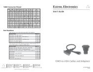
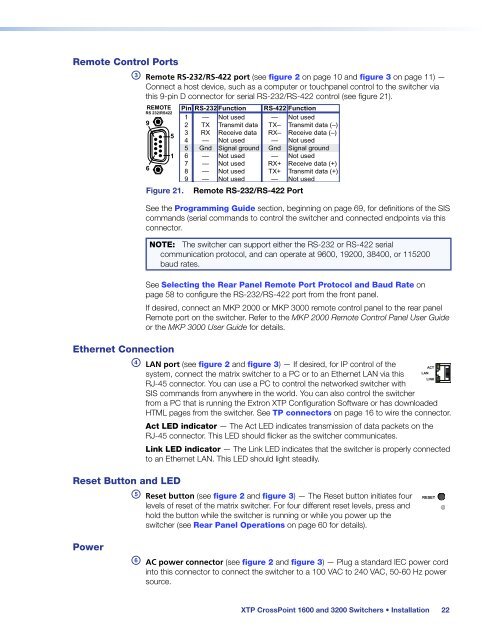
c Remote RS-232/RS-422 port (see figure 2 on page 10 <strong>and</strong> figure 3 on page 11) —<br />
Connect a host device, such as a computer or touchpanel control to the switcher via<br />
this 9-pin D connector for serial RS-232/RS-422 control (see figure 21).<br />
REMOTE<br />
RS 232/RS422<br />
9<br />
6<br />
5<br />
1<br />
Figure 21.<br />
Pin RS-232 Function<br />
1<br />
2<br />
3<br />
4<br />
5<br />
6<br />
7<br />
8<br />
9<br />
—<br />
TX<br />
RX<br />
—<br />
Gnd<br />
—<br />
—<br />
—<br />
—<br />
Not used<br />
Transmit data<br />
Receive data<br />
Not used<br />
Signal ground<br />
Not used<br />
Not used<br />
Not used<br />
Not used<br />
RS-422 Function<br />
— Not used<br />
TX– Transmit data (–)<br />
RX– Receive data (–)<br />
— Not used<br />
Gnd Signal ground<br />
— Not used<br />
RX+ Receive data (+)<br />
TX+ Transmit data (+)<br />
— Not used<br />
Remote RS-232/RS-422 Port<br />
See the Programming Guide section, beginning on page 69, for definitions of the SIS<br />
comm<strong>and</strong>s (serial comm<strong>and</strong>s to control the switcher <strong>and</strong> connected endpoints via this<br />
connector.<br />
NOTE: The switcher can support either the RS-232 or RS-422 serial<br />
communication protocol, <strong>and</strong> can operate at 9600, 19200, 38400, or 115200<br />
baud rates.<br />
See Selecting the Rear Panel Remote Port Protocol <strong>and</strong> Baud Rate on<br />
page 58 to configure the RS-232/RS-422 port from the front panel.<br />
If desired, connect an MKP 2000 or MKP 3000 remote control panel to the rear panel<br />
Remote port on the switcher. Refer to the MKP 2000 Remote Control Panel User Guide<br />
or the MKP 3000 User Guide for details.<br />
Ethernet Connection<br />
d LAN port (see figure 2 <strong>and</strong> figure 3) — If desired, for IP control of the<br />
system, connect the matrix switcher to a PC or to an Ethernet LAN via this<br />
RJ-45 connector. You can use a PC to control the networked switcher with<br />
SIS comm<strong>and</strong>s from anywhere in the world. You can also control the switcher<br />
ACT<br />
LAN<br />
LINK<br />
from a PC that is running the <strong>Extron</strong> <strong>XTP</strong> Configuration Software or has downloaded<br />
HTML pages from the switcher. See TP connectors on page 16 to wire the connector.<br />
Act LED indicator — The Act LED indicates transmission of data packets on the<br />
RJ-45 connector. This LED should flicker as the switcher communicates.<br />
Link LED indicator — The Link LED indicates that the switcher is properly connected<br />
to an Ethernet LAN. This LED should light steadily.<br />
Reset Button <strong>and</strong> LED<br />
e Reset button (see figure 2 <strong>and</strong> figure 3) — The Reset button initiates four RESET<br />
levels of reset of the matrix switcher. For four different reset levels, press <strong>and</strong><br />
hold the button while the switcher is running or while you power up the<br />
switcher (see Rear Panel Operations on page 60 for details).<br />
Power<br />
f AC power connector (see figure 2 <strong>and</strong> figure 3) — Plug a st<strong>and</strong>ard IEC power cord<br />
into this connector to connect the switcher to a 100 VAC to 240 VAC, 50-60 Hz power<br />
source.<br />
<strong>XTP</strong> <strong>CrossPoint</strong> <strong>1600</strong> <strong>and</strong> <strong>3200</strong> Switchers • Installation 22