Extron XTP CrossPoint 1600 and 3200 ... - Extron Electronics
Extron XTP CrossPoint 1600 and 3200 ... - Extron Electronics
Extron XTP CrossPoint 1600 and 3200 ... - Extron Electronics

Create successful ePaper yourself
Turn your PDF publications into a flip-book with our unique Google optimized e-Paper software.
1d<br />
IR/RS-232 Over <strong>XTP</strong> Connectors — If desired, connect serial RS-232 signals,<br />
modulated IR signals, or both to these 3.5 mm, 5-pole captive screw connectors<br />
for bidirectional RS-232 <strong>and</strong> IR communications on the associated inputs. See<br />
RS-232 <strong>and</strong> IR connectors on page 18 to wire the connectors.<br />
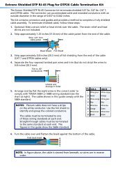
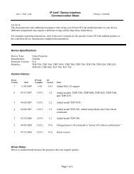
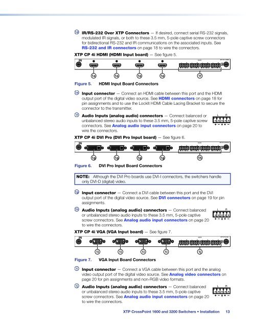
<strong>XTP</strong> CP 4i HDMI (HDMI Input board) — See figure 5.<br />
IN<br />
AUDIO<br />
L R L R L R L R<br />
<strong>XTP</strong> CP 4i HDMI<br />
IN<br />
1e<br />
1e<br />
1e<br />
1e<br />
1f<br />
Figure 5.<br />
HDMI Input Board Connectors<br />
1e<br />
Input connector — Connect an HDMI cable between this port <strong>and</strong> the HDMI<br />
output port of the digital video source. See HDMI connectors on page 18 for<br />
pin assignments <strong>and</strong> to use the LockIt HDMI Cable Lacing Bracket to secure the<br />
connector to the transmitter.<br />
1f<br />
Audio Inputs (analog audio) connectors — Connect balanced or<br />
unbalanced stereo audio inputs to these 3.5 mm, 5-pole captive screw<br />
connectors. See Analog audio input connectors on page 20 to<br />
wire the connectors.<br />
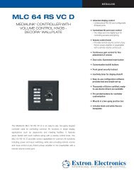
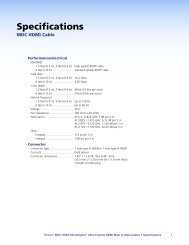
<strong>XTP</strong> CP 4i DVI Pro (DVI Pro Input board) — See figure 6.<br />
IN<br />
AUDIO<br />
L R L R L R L R<br />
<strong>XTP</strong> CP 4i DVI Pro<br />
IN<br />
1g<br />
1g<br />
1g<br />
1g<br />
1h<br />
Figure 6.<br />
DVI Pro Input Board Connectors<br />
NOTE: Although the DVI Pro boards use DVI-I connectors, the switchers h<strong>and</strong>le<br />
only DVI-D (digital) video.<br />
1g<br />
Input connector — Connect a DVI cable between this port <strong>and</strong> the DVI<br />
output port of the digital video source. See DVI connectors on page 19 for pin<br />
assignments.<br />
1h<br />
Audio Inputs (analog audio) connectors — Connect balanced<br />
or unbalanced stereo audio inputs to these 3.5 mm, 5-pole captive<br />
screw connectors. See Analog audio input connectors on page 20<br />
to wire the connectors.<br />
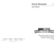
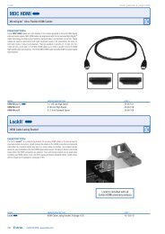
<strong>XTP</strong> CP 4i VGA (VGA Input board) — See figure 7.<br />
IN<br />
AUDIO<br />
L R L R L R L R<br />
<strong>XTP</strong> CP 4i VGA<br />
IN<br />
1i<br />
1i<br />
1i<br />
1i<br />
1j<br />
Figure 7.<br />
VGA Input Board Connectors<br />
1i<br />
Input connector — Connect a VGA cable between this port <strong>and</strong> the analog<br />
video output port of the digital video source. See Analog video connectors on<br />
page 20 for pin assignments <strong>and</strong> non-RGB video formats.<br />
1j<br />
Audio Inputs (analog audio) connectors — Connect balanced<br />
or unbalanced stereo audio inputs to these 3.5 mm, 5-pole captive<br />
screw connectors. See Analog audio input connectors on page 20<br />
to wire the connectors.<br />
<strong>XTP</strong> <strong>CrossPoint</strong> <strong>1600</strong> <strong>and</strong> <strong>3200</strong> Switchers • Installation 13