Extron XTP CrossPoint 1600 and 3200 ... - Extron Electronics
Extron XTP CrossPoint 1600 and 3200 ... - Extron Electronics
Extron XTP CrossPoint 1600 and 3200 ... - Extron Electronics

You also want an ePaper? Increase the reach of your titles
YUMPU automatically turns print PDFs into web optimized ePapers that Google loves.
ACT<br />
LAN<br />
LINK<br />
RESET<br />
50-60Hz<br />
-A MAX<br />
IR/RS-232 OVER <strong>XTP</strong><br />
IR/RS-232 OVER <strong>XTP</strong><br />
SIG LINK<br />
SIG LINK<br />
SIG LINK<br />
SIG LINK<br />
PWR<br />
PWR<br />
PWR<br />
PWR<br />
ACT LINK<br />
ACT LINK<br />
ACT LINK<br />
ACT LAN LINK<br />
<strong>XTP</strong><br />
SIG LINK<br />
SIG LINK<br />
SIG LINK<br />
SIG LINK<br />
PWR<br />
PWR<br />
PWR<br />
PWR<br />
ACT LINK<br />
ACT LINK<br />
ACT LINK<br />
ACT LAN LINK<br />
<strong>XTP</strong><br />
U<br />
T<br />
I<br />
N<br />
P<br />
U<br />
P<br />
T<br />
U<br />
T<br />
S<br />
IR/RS-232 OVER <strong>XTP</strong><br />
IR/RS-232 OVER <strong>XTP</strong><br />
SIG LINK<br />
SIG LINK<br />
SIG LINK<br />
SIG LINK<br />
PWR<br />
PWR<br />
PWR<br />
PWR<br />
ACT LINK<br />
ACT LINK<br />
ACT LINK<br />
ACT LAN LINK<br />
<strong>XTP</strong><br />
SIG LINK<br />
SIG LINK<br />
SIG LINK<br />
SIG LINK<br />
PWR<br />
PWR<br />
PWR<br />
PWR<br />
ACT LINK<br />
ACT LINK<br />
ACT LINK<br />
ACT LAN LINK<br />
<strong>XTP</strong><br />
AUDIO<br />
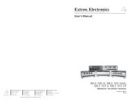
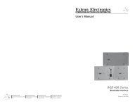
Removing <strong>and</strong> Installing an Input or Output Board or Blank Panel<br />
Circuit boards can be replaced for fault correction. They can be added or removed to<br />
increase or decrease the Input or output configuration (size) of the <strong>XTP</strong> <strong>CrossPoint</strong> switcher.<br />
ATTENTION: Do not touch the electronic components or the backplane or circuit<br />
board connectors without being electrically grounded. H<strong>and</strong>le circuit boards by their<br />
edges only. ESD can damage circuits, even if you cannot feel, see, or hear it.<br />
NOTES:<br />
• For proper cooling <strong>and</strong> air flow, boards or blank panels should be installed in all<br />
locations during normal switcher operations.<br />
• The Input <strong>and</strong> output boards are hot-swappable. You do not need to power down<br />
the switcher to remove or install an Input or output board.<br />
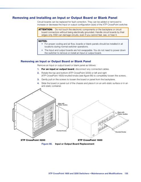
Removing an Input or Output Board or Blank Panel<br />
Remove an Input or output board or blank panel as follows:<br />
1. For an input or output board, disconnect any connected cables.<br />
2. Rotate the top <strong>and</strong> bottom (<strong>XTP</strong> <strong>CrossPoint</strong> <strong>3200</strong>) or left <strong>and</strong> right<br />
(<strong>XTP</strong> <strong>CrossPoint</strong> <strong>1600</strong>) knurled knobs (see figure 66) to completely loosen the screws.<br />
3. Gently pull on the screws to loosen the board or panel from the backplane.<br />
4. Slide the board or panel out of the chassis <strong>and</strong> place it on an anti-static surface or in an<br />
anti-static container.<br />
1 0-240V<br />
REMOTE<br />
RS 232/RS4 2<br />
DISCO NECT POWER<br />
CORD BEFORE<br />
SERVICING<br />
AUDIO<br />
<strong>XTP</strong> CP 4i HDMI<br />
IN<br />
L R L R L R L R<br />
AUDIO<br />
<strong>XTP</strong> CP 4i HDMI<br />
IN<br />
L R L R L R L R<br />
IN<br />
IN<br />
AUDIO<br />
<strong>XTP</strong> CP 4i DVI Pro<br />
IN<br />
L R L R L R L R<br />
AUDIO<br />
<strong>XTP</strong> CP 4i DVI Pro<br />
IN<br />
L R L R L R L R<br />
IN<br />
IN<br />
AUDIO<br />
<strong>XTP</strong> CP 4i VGA<br />
IN<br />
L R L R L R L R<br />
IN<br />
AUDIO<br />
<strong>XTP</strong> CP 4i VGA<br />
IN<br />
L R L R L R L R<br />
IN<br />
<strong>XTP</strong> CP 4i<br />
IN<br />
RS-232 IR RS-232 IR RS-232 IR RS-232 IR<br />
IN<br />
LAN LAN LAN <strong>XTP</strong><br />
<strong>XTP</strong><br />
<strong>XTP</strong><br />
Tx Rx Tx Rx Tx Rx Tx Rx Tx Rx Tx Rx Tx Rx Tx Rx<br />
<strong>XTP</strong> CP 4i<br />
IN<br />
RS-232 IR RS-232 IR RS-232 IR RS-232 IR<br />
IN<br />
LAN LAN LAN <strong>XTP</strong><br />
<strong>XTP</strong><br />
<strong>XTP</strong><br />
Tx Rx Tx Rx Tx Rx Tx Rx Tx Rx Tx Rx Tx Rx Tx Rx<br />
S<br />
O<br />
AUDIO<br />
<strong>XTP</strong> CP 4o HDMI<br />
OUT<br />
L R L R L R L R<br />
AUDIO<br />
<strong>XTP</strong> CP 4o HDMI<br />
OUT<br />
L R L R L R L R<br />
OUT OUT<br />
AUDIO<br />
<strong>XTP</strong> CP 4o DVI Pro<br />
OUT<br />
L R L R L R L R<br />
AUDIO<br />
<strong>XTP</strong> CP 4o DVI Pro<br />
OUT<br />
L R L R L R L R<br />
OUT OUT<br />
<strong>XTP</strong> CP 4o<br />
OUT<br />
RS-232 IR RS-232 IR RS-232 IR RS-232 IR<br />
LAN LAN LAN <strong>XTP</strong><br />
<strong>XTP</strong><br />
<strong>XTP</strong><br />
Tx Rx Tx Rx Tx Rx Tx Rx Tx Rx Tx Rx Tx Rx Tx Rx<br />
<strong>XTP</strong> CP 4o<br />
OUT<br />
RS-232 IR RS-232 IR RS-232 IR RS-232 IR<br />
LAN LAN LAN <strong>XTP</strong><br />
<strong>XTP</strong><br />
<strong>XTP</strong><br />
Tx Rx Tx Rx Tx Rx Tx Rx Tx Rx Tx Rx Tx Rx Tx Rx<br />
AUDIO<br />
<strong>XTP</strong> CP 4o SA<br />
OUT<br />
L R L R L R L R<br />
OUT OUT OUT<br />
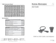
Align with<br />
Plastic Guides<br />
Knurled Knobs<br />
IN<br />
Align with<br />
Plastic Guides<br />
L R L R L R L R<br />
Knurled Knobs<br />
<strong>XTP</strong> CP 4i HDMI<br />
IN<br />
<strong>XTP</strong> <strong>CrossPoint</strong> <strong>3200</strong> <strong>XTP</strong> <strong>CrossPoint</strong> <strong>1600</strong><br />
Figure 66. Input or Output Board Replacement<br />
<strong>XTP</strong> <strong>CrossPoint</strong> <strong>1600</strong> <strong>and</strong> <strong>3200</strong> Switchers • Maintenance <strong>and</strong> Modifications 135