Extron XTP CrossPoint 1600 and 3200 ... - Extron Electronics
Extron XTP CrossPoint 1600 and 3200 ... - Extron Electronics
Extron XTP CrossPoint 1600 and 3200 ... - Extron Electronics

You also want an ePaper? Increase the reach of your titles
YUMPU automatically turns print PDFs into web optimized ePapers that Google loves.
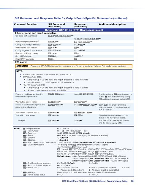
SIS Comm<strong>and</strong> <strong>and</strong> Response Table for Output-Board-Specific Comm<strong>and</strong>s (continued)<br />
Comm<strong>and</strong> Function<br />
SIS Comm<strong>and</strong><br />
(Host to Unit)<br />
Response<br />
(Unit to Host)<br />
Outputs on <strong>XTP</strong> CP 4o [<strong>XTP</strong>] Boards (continued)<br />
Ethernet serial port insert parameters<br />
Set serial port parameters EX1^*X1& , X1* , X1( , X2) CP }<br />
CpnX1^•Ccp X1& , X1* , X1( , X2)]<br />
Read serial port parameters EX1^CP } X1&,X1*,X1(,X2)]<br />
Configure current port timeout E 0* X2! TC } Pti0*X2!]<br />
Read current port timeout E 0TC } X2!]<br />
Configure global IP port timeout E 1* X2! TC } Pti1*X2!]<br />
Read global IP port timeout E 1TC } X2!]<br />
Set UART start point EX2@ MD } PmdX2@]<br />
Read UART start point E MD } X2@]<br />
<strong>XTP</strong> power<br />
Additional description<br />
ATTENTION:<br />
Power over <strong>XTP</strong> (PoX) is intended for indoors use only. No part of a network that uses PoX can be routed outdoors.<br />
NOTE:<br />
• PoX is supplied by the <strong>XTP</strong> <strong>CrossPoint</strong> 48 V power supply.<br />
• <strong>XTP</strong> <strong>CrossPoint</strong> <strong>1600</strong>:<br />
• Can power up to 28 total (input <strong>and</strong> output) endpoints at up to 364 watts.<br />
• Is available with optional 48 V power supply redundancy.<br />
• The <strong>XTP</strong> <strong>CrossPoint</strong> <strong>3200</strong>:<br />
• Can power up to 24 total (input <strong>and</strong> output) endpoints at up to 312 watts.<br />
• No 48 V power supply redundancy is available.<br />
Enable or disable power to output<br />
endpoint <strong>and</strong> report status<br />
E O X@ * X2# POEC } PoecOX@ * X2# * X2$ * X2%] Enable or disable (X2#) remote power on<br />
output X@. The endpoint is requesting<br />
X2$ watts <strong>and</strong> the power status is X2%.<br />
View output power status E O X@ POEC } X2# * X2$ * X2%]<br />
Enable or disable output power <strong>and</strong><br />
report status, all outputs<br />
E O X2# *POEC } PoecO00*X2# 1 X2# 2 ... X2# n ] Each X2# is the enable or disable<br />
status of an output, starting at output<br />
1. n is 16 or 32.<br />
View all output power status E OPOEC } X2# 1 X2# 2 X2# 3 ... X2# n ]<br />
View <strong>XTP</strong> power usage E TPOEC } X2^*X2&] Show PoX wattage applied <strong>and</strong> the<br />
status of the 48 V power supply.<br />
Example: E TPOEC } 450*0] The switcher is providing 45.0 watts<br />
<strong>and</strong> the power supply is Ok.<br />
NOTE: X@ = Output number 01 – 16 or 32<br />
X1^ = Port number 35 —66 = UARTs (outputs) 1 — 32<br />
X1& = Baud rate<br />
9600, 19200, 38400, 115200 (default)<br />
X1* = Parity odd, even, none, mark, space (only the first letter is required)<br />
X1( = Data bits 7, 8 (default)<br />
X2) = Stop bits 1 (default), 2<br />
X2! = Port timeout (10-sec. increments) 1 (= 10 seconds) - 65000 (default is 30 = 300 seconds = 5 minutes)<br />
X2@ = UART starting point<br />
The starting point (X2@) is the rear panel RS-232/RS-422 port.<br />
The next position (X2@ +1 ) is not used.<br />
X2@ +2 through X2@ +18 (<strong>XTP</strong> <strong>CrossPoint</strong> <strong>1600</strong>) or X2@ +34 (<strong>XTP</strong> <strong>CrossPoint</strong> <strong>3200</strong>) are <strong>XTP</strong> inputs.<br />
For the <strong>XTP</strong> <strong>CrossPoint</strong> <strong>1600</strong>, X2@ +19 through X2@ +34 are <strong>XTP</strong> outputs.<br />
For the <strong>XTP</strong> <strong>CrossPoint</strong> <strong>3200</strong>, X2@ +35 through X2@ +66 are <strong>XTP</strong> outputs.<br />
Default values: 1999 = Rear panel Remote RS-232/RS-422 port, 2000 = Unused<br />
2017 through 2032 (<strong>XTP</strong> <strong>CrossPoint</strong> <strong>1600</strong>) = Output 1 through 16<br />
2033 through 2064 (<strong>XTP</strong> <strong>CrossPoint</strong> <strong>3200</strong>) = Output 1 through 32<br />
X2# = Enable or disable for power 0 = Disable (default) 1 = Enable<br />
X2$ = Amount of power requested 00 or 13 (watts)<br />
X2% = Power status 0 = Unpowered endpoint 2 = Power available but disabled 4 = Fault<br />
1 = Power provided to endpoint 3 = No power available, but enabled<br />
X2^ = Wattage<br />
Power usage in 0.1 watt increments. Example: 260 = 26.0 watts watts<br />
X2& = Power supply status 0 = Ok 1 = Not Ok<br />
<strong>XTP</strong> <strong>CrossPoint</strong> <strong>1600</strong> <strong>and</strong> <strong>3200</strong> Switchers • Programming Guide 98