Extron XTP CrossPoint 1600 and 3200 ... - Extron Electronics
Extron XTP CrossPoint 1600 and 3200 ... - Extron Electronics
Extron XTP CrossPoint 1600 and 3200 ... - Extron Electronics

You also want an ePaper? Increase the reach of your titles
YUMPU automatically turns print PDFs into web optimized ePapers that Google loves.
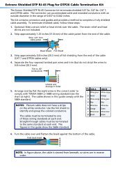
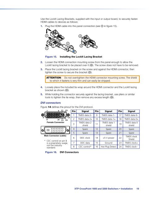
Use the LockIt Lacing Brackets, supplied with the input or output board, to securely fasten<br />
HDMI cables to devices as follows:<br />
1. Plug the HDMI cable into the panel connection (see a in figure 15).<br />
3<br />
4<br />
3<br />
1<br />
2<br />
5<br />
Figure 15.<br />
Installing the LockIt Lacing Bracket<br />
2. Loosen the HDMI connection mounting screw from the panel enough to allow the<br />
LockIt lacing bracket to be placed over it (b). The screw does not have to be removed.<br />
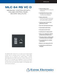
3. Place the LockIt lacing bracket on the screw <strong>and</strong> against the HDMI connector, then<br />
tighten the screw to secure the bracket (c).<br />
ATTENTION: Do not overtighten the HDMI connector mounting screw. The shield<br />
to which it fastens is very thin <strong>and</strong> can easily be stripped.<br />
4. Loosely place the included tie wrap around the HDMI connector <strong>and</strong> the LockIt lacing<br />
bracket as shown (d).<br />
5. While holding the connector securely against the lacing bracket, use pliers or similar<br />
tools to tighten the tie wrap, then remove any excess length (e).<br />
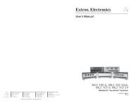
DVI connectors<br />
Figure 14 defines the pinout for the DVI protocol.<br />
9<br />
1<br />
C5<br />
17 24 C3 C4<br />
Female Connector<br />
Male Connector (cable)<br />
* CEC control on pin 8<br />
is a proprietary usage,<br />
not the industry<br />
st<strong>and</strong>ard.<br />
Figure 16.<br />
8<br />
C1<br />
C2<br />
Pin<br />
DVI Connectors<br />
Signal<br />
Pin<br />
Signal<br />
Pin<br />
1<br />
2<br />
TMDS data 2–<br />
TMDS data 2+<br />
9<br />
10<br />
TMDS data 1–<br />
TMDS data 1+<br />
17<br />
18<br />
3<br />
TMDS data 2 TMDS data 1<br />
11<br />
shield<br />
shield<br />
19<br />
4 Spare 12 Spare 20<br />
5 Spare 13 Spare 21<br />
6 DDC clock 14 +5 V power 22<br />
7 DDC data 15 Ground 23<br />
8 CEC control* 16 Hot Plug Detect 24<br />
Signal<br />
TMDS data 0–<br />
TMDS data 0+<br />
TMDS data 0<br />
shield<br />
Spare<br />
Spare<br />
TMDS clock<br />
Shield<br />
TMDS clock+<br />
TMDS clock–<br />
<strong>XTP</strong> <strong>CrossPoint</strong> <strong>1600</strong> <strong>and</strong> <strong>3200</strong> Switchers • Installation 19