Extron XTP CrossPoint 1600 and 3200 ... - Extron Electronics
Extron XTP CrossPoint 1600 and 3200 ... - Extron Electronics
Extron XTP CrossPoint 1600 and 3200 ... - Extron Electronics

Create successful ePaper yourself
Turn your PDF publications into a flip-book with our unique Google optimized e-Paper software.
Front Panel Configuration Port <strong>and</strong> Power LEDs<br />
CONTROL<br />
I/O<br />
CONTROL<br />
I/O<br />
CONFIG<br />
AUDIO<br />
VIDEO<br />
ENTER PRESET VIEW ESC<br />
ENTER PRESET VIEW ESC AUDIO<br />
VIDEO<br />
CONFIG<br />
PRIMARY<br />
1 2<br />
REDUNDANT<br />
POWER<br />
1 3<br />
2 4<br />
POWER<br />
<strong>XTP</strong> CROSSPOINT <strong>1600</strong><br />
<strong>XTP</strong> SERIES DIGITAL MATRIX SWITCHER<br />
<strong>XTP</strong> CROSSPOINT <strong>3200</strong><br />
<strong>XTP</strong> SERIES DIGITAL MATRIX SWITCHER<br />
1 2<br />
<strong>XTP</strong> <strong>CrossPoint</strong> <strong>1600</strong><br />
1 2<br />
<strong>XTP</strong> <strong>CrossPoint</strong> <strong>3200</strong><br />
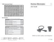
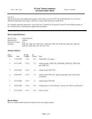
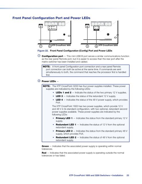
Figure 22. Front Panel Configuration (Config) Port <strong>and</strong> Power LEDs<br />
a Configuration port — This mini USB B port serves a similar communications function<br />
as the rear panel Remote port, but it is easier to access than the rear port after the<br />
matrix switcher has been installed <strong>and</strong> cabled.<br />
NOTE: A front panel Configuration port connection <strong>and</strong> a rear panel Remote<br />
port connection can both be active at the same time. If comm<strong>and</strong>s are sent<br />
simultaneously to both, the comm<strong>and</strong> that reaches the processor first is h<strong>and</strong>led<br />
first.<br />
b Power LEDs —<br />
NOTE: The <strong>XTP</strong> <strong>CrossPoint</strong> <strong>3200</strong> has four power supplies installed. These power<br />
supplies are indicated by the following LEDs:<br />
• LEDs 1 <strong>and</strong> 2 — Indicate the status of the two primary 12 V supplies.<br />
• LED 3 — Indicates the status of the redundant 12 V supply.<br />
• LED 4 — Indicates the status of the 48 V power supply, which provides<br />
PoX.<br />
The <strong>XTP</strong> <strong>CrossPoint</strong> <strong>1600</strong> has two power supplies, which provide 12 V<br />
<strong>and</strong> 48 V in its st<strong>and</strong>ard configuration, with two optional, redundant second<br />
power supplies available. These power supplies are indicated by the<br />
following LEDs:<br />
• Primary LED 1 — Indicates the status from the st<strong>and</strong>ard primary 12 V<br />
supply.<br />
• Redundant LED 1 — Indicates the status of 12 V from the optional<br />
redundant supply.<br />
• Primary LED 2 — Indicates the status from the st<strong>and</strong>ard primary 48 V<br />
supply, which provides PoX.<br />
• Redundant LED 2 — Indicates the status of 48 V from the optional<br />
redundant supply.<br />
Green — Indicates that the associated power supply is operating within normal<br />
tolerances.<br />
Red — Indicates that the associated power supply is operating outside the normal<br />
tolerances or has failed.<br />
<strong>XTP</strong> <strong>CrossPoint</strong> <strong>1600</strong> <strong>and</strong> <strong>3200</strong> Switchers • Installation 23