Extron XTP CrossPoint 1600 and 3200 ... - Extron Electronics
Extron XTP CrossPoint 1600 and 3200 ... - Extron Electronics
Extron XTP CrossPoint 1600 and 3200 ... - Extron Electronics
You also want an ePaper? Increase the reach of your titles
YUMPU automatically turns print PDFs into web optimized ePapers that Google loves.
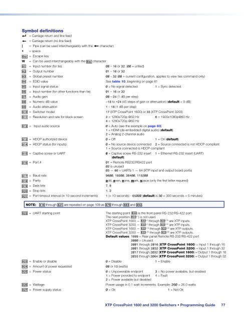
Symbol definitions<br />
] = Carriage return <strong>and</strong> line feed<br />
} = Carriage return (no line feed)<br />
| = Pipe (can be used interchangeably with the } character)<br />
• = space<br />
E = Escape key<br />
W = Can be used interchangeably with the E character<br />
X! = Input number (for tie) 00 – 16 or 32 (00 = untied)<br />
X@ = Output number 01 – 16 or 32<br />
X# = Global preset number 00 – 32 (00 = current configuration, applies to view ties comm<strong>and</strong> only)<br />
X$ = EDID value See table 10, beginning on page 81<br />
X% = Input signal status 0 = No signal detected 1 = Sync detected<br />
X^ = Input number (for other functions than tie) 01 – 16 or 32<br />
X& = Audio gain<br />
00 – 24 (1 dB per step)<br />
X* = Numeric dB value –18 to +24 (45 steps of gain or attenuation) (default = 0 dB)<br />
X( = Audio attenuation 1 – 18 (1 dB per step)<br />
X1) = Switcher model 17 (<strong>XTP</strong> <strong>CrossPoint</strong> <strong>1600</strong>) or 33 (<strong>XTP</strong> <strong>CrossPoint</strong> <strong>3200</strong>)<br />
X1! = Resolution <strong>and</strong> rate for black screen 2 = 1280x720p @50 Hz 6 = 1920x1080p@60 Hz<br />
4 = 1280x720p @60 Hz<br />
X1@ = Input audio source 0 = Auto (see the example on page 83)<br />
1 = HDMI (de-embedded digital audio) (default)<br />
2 = Analog 2-channel audio<br />
X1# = HDCP authorized device 0 = Off 1 = On (default)<br />
X1$ = HDCP status (for inputs) 0 = No source device connected 2 = Source connected is not HDCP-compliant<br />
1 = Source connected is HDCP-compliant<br />
X1% = Captive screw or UART 0 = Captive screw RS-232 insert 1 = Ethernet RS-232 insert (UART)<br />
(default)<br />
X1^ = Port #<br />
01 = Remote RS232/RS422 port<br />
02 is unused<br />
03 — 66 = UARTs 1 — 64 (<strong>XTP</strong> input <strong>and</strong> output board ports)<br />
X1& = Baud rate 9600, 19200, 38400, 115200<br />
X1* = Parity odd, even, none, mark, space (only the first letter required)<br />
X1( = Data bits 7, 8<br />
X2) = Stop bits 1, 2<br />
X2! = Port timeout interval (in 10-second increments) 1 (= 10 seconds) - 65000 (default is 30 = 300 seconds = 5 minutes)<br />
NOTE: X1^ through X2! are repeated on page 109 as X7( through X8# <strong>and</strong> X9@.<br />
X2@ = UART starting point<br />
The starting point (X2@) is the front panel RS-232/RS-422 port.<br />
The next position (X2@ +1 ) is not used.<br />
<strong>XTP</strong> <strong>CrossPoint</strong> <strong>1600</strong> — X2@ +2 through X2@ +18 are <strong>XTP</strong> inputs.<br />
<strong>XTP</strong> <strong>CrossPoint</strong> <strong>3200</strong> — X2@ +2 through X2@ +34 are <strong>XTP</strong> inputs.<br />
<strong>XTP</strong> <strong>CrossPoint</strong> <strong>1600</strong> — X2@ +19 through X2@ +34 are <strong>XTP</strong> outputs.<br />
<strong>XTP</strong> <strong>CrossPoint</strong> <strong>3200</strong> — X2@ +35 through X2@ +66 are <strong>XTP</strong> outputs.<br />
Default values: 1999 = Rear panel Remote RS-232/RS-422 port<br />
2000 = Unused<br />
2001 through 2016 (<strong>XTP</strong> <strong>CrossPoint</strong> <strong>1600</strong>) = Input 1 through 16<br />
2001 through 2032 (<strong>XTP</strong> <strong>CrossPoint</strong> <strong>3200</strong>) = Input 1 through 32<br />
2017 through 2032 (<strong>XTP</strong> <strong>CrossPoint</strong> <strong>1600</strong>) = Output 1 through 16<br />
2033 through 2064 (<strong>XTP</strong> <strong>CrossPoint</strong> <strong>3200</strong>) = Output 1 through 32<br />
X2# = Enable or disable 0 = Disable 1 = Enable<br />
X2$ = Amount of power requested 00 or 13 (watts)<br />
X2% = Power status 0 = Unpowerable endpoint 3 = No power available, but enabled<br />
1 = Power provided to endpoint 4 = Fault<br />
2 = Power available but disabled<br />
X2^ = Wattage<br />
Power usage in 0.1 watt increments. Example: 260 = 26.0 watts<br />
X2& = Power supply status 0 = Ok 1 = Not Ok<br />
<strong>XTP</strong> <strong>CrossPoint</strong> <strong>1600</strong> <strong>and</strong> <strong>3200</strong> Switchers • Programming Guide 77


