Extron XTP CrossPoint 1600 and 3200 ... - Extron Electronics
Extron XTP CrossPoint 1600 and 3200 ... - Extron Electronics
Extron XTP CrossPoint 1600 and 3200 ... - Extron Electronics

You also want an ePaper? Increase the reach of your titles
YUMPU automatically turns print PDFs into web optimized ePapers that Google loves.
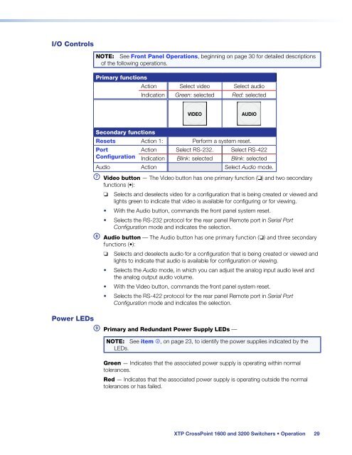
I/O Controls<br />
NOTE: See Front Panel Operations, beginning on page 30 for detailed descriptions<br />
of the following operations.<br />
Primary functions<br />
Action Select video Select audio<br />
Indication Green: selected Red: selected<br />
VIDEO<br />
AUDIO<br />
Secondary functions<br />
Resets Action 1: Perform a system reset.<br />
Port<br />
Action Select RS-232. Select RS-422<br />
Configuration Indication Blink: selected Blink: selected<br />
Audio Action Select Audio mode.<br />
g Video button — The Video button has one primary function (❏) <strong>and</strong> two secondary<br />
functions (•):<br />
❏ Selects <strong>and</strong> deselects video for a configuration that is being created or viewed <strong>and</strong><br />
lights green to indicate that video is available for configuring or for viewing.<br />
• With the Audio button, comm<strong>and</strong>s the front panel system reset.<br />
• Selects the RS-232 protocol for the rear panel Remote port in Serial Port<br />
Configuration mode <strong>and</strong> indicates the selection.<br />
h Audio button — The Audio button has one primary function (❏) <strong>and</strong> three secondary<br />
functions (•):<br />
❏ Selects <strong>and</strong> deselects audio for a configuration that is being created or viewed <strong>and</strong><br />
lights to indicate that audio is available for configuration or viewing.<br />
• Selects the Audio mode, in which you can adjust the analog input audio level <strong>and</strong><br />
the analog output audio volume.<br />
• With the Video button, comm<strong>and</strong>s the front panel system reset.<br />
• Selects the RS-422 protocol for the rear panel Remote port in Serial Port<br />
Configuration mode <strong>and</strong> indicates the selection.<br />
Power LEDs<br />
i Primary <strong>and</strong> Redundant Power Supply LEDs —<br />
NOTE: See item b, on page 23, to identify the power supplies indicated by the<br />
LEDs.<br />
Green — Indicates that the associated power supply is operating within normal<br />
tolerances.<br />
Red — Indicates that the associated power supply is operating outside the normal<br />
tolerances or has failed.<br />
<strong>XTP</strong> <strong>CrossPoint</strong> <strong>1600</strong> <strong>and</strong> <strong>3200</strong> Switchers • Operation 29