ThorPlas Engineering Manual - Thordon Bearings
ThorPlas Engineering Manual - Thordon Bearings
ThorPlas Engineering Manual - Thordon Bearings

Create successful ePaper yourself
Turn your PDF publications into a flip-book with our unique Google optimized e-Paper software.
DESIGN GUIDE<br />
d) PV Limits<br />
For proper bearing performance, two factors must<br />
be considered:<br />
• operating pressure<br />
• velocity at the contact surface<br />
The result of multiplying the pressure by the linear<br />
velocity is referred to as a PV value. The combination<br />
of pressure and velocity causes heat generation at the<br />
bearing surface. If this heat is not removed from<br />
the bearing surface, it can cause premature bearing<br />
failure due to overheating and wear.<br />
The PV limits in Figure 5 have been developed to ensure<br />
the proper design of <strong>ThorPlas</strong> bearings.<br />
If the frictional heat generated is removed by a sufficient<br />
flow of cooling lubricant such as water or process liquid,<br />
<strong>ThorPlas</strong> bearings will perform well at velocities far<br />
outside the limits shown on the PV limits. Typical<br />
applications where this occurs include vertical pump<br />
bearings where a constant flow of cool water is provided.<br />
The minimum recommended cooling water flow rate<br />
is 0.15 litres/minute/mm (1 US Gal/minute/inch) of<br />
shaft diameter.<br />
Note 1: The size of the water bath should be such that the heat<br />
generated by friction does not increase the water temperature above<br />
80°C (176°F).<br />
Note 2: For guidance on potential applications that fall outside the PV<br />
limits contact <strong>Thordon</strong> <strong>Bearings</strong> Inc. or your local <strong>Thordon</strong> distributor.<br />
Note 3: PV values are given by many non-metallic material manufacturers<br />
and are often published with several incorrect assumptions. The first is<br />
that the individual P and V values have little importance, as long as they<br />
are with the product value range. The second, and perhaps the most<br />
dangerous assumption is the limited amount of test time used to develop<br />
the P and V values. No formal consideration is given to the time factor.<br />
Note 4: These guideline values are supplied for reference only. PV limits<br />
for any material vary with different combinations of pressure and velocity<br />
as well as with other test conditions.<br />
8<br />
Figure 5: PV Limits<br />
Operating PV Limit PV Limit<br />
Condition (MPa - m/min.) (psi - fpm)<br />
Full rotation – dry 7.35 3500<br />
Full rotation – cooled<br />
(water bath)<br />
24 12000<br />
1<br />
Full rotation – continuous<br />
cool water supply<br />
147.14 70000<br />
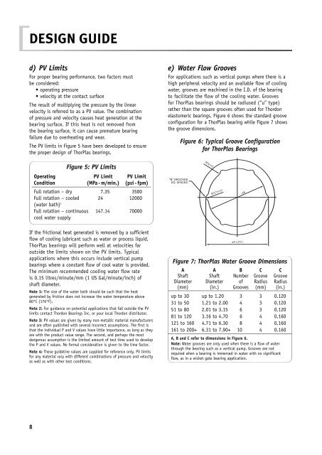
e) Water Flow Grooves<br />
For applications such as vertical pumps where there is a<br />
high peripheral velocity and an available flow of cooling<br />
water, grooves are machined in the I.D. of the bearing<br />
to facilitate the flow of the cooling water. Grooves<br />
for <strong>ThorPlas</strong> bearings should be radiused (“u” type)<br />
rather than the square grooves often used for <strong>Thordon</strong><br />
elastomeric bearings. Figure 6 shows the standard groove<br />
configuration for a <strong>ThorPlas</strong> bearing while Figure 7 shows<br />
the groove dimensions.<br />
Figure 6: Typical Groove Configuration<br />
for <strong>ThorPlas</strong> <strong>Bearings</strong><br />
Figure 7: <strong>ThorPlas</strong> Water Groove Dimensions<br />
A A B C C<br />
Shaft Shaft Number Groove Groove<br />
Diameter Diameter of Radius Radius<br />
(mm) (in.) Grooves (mm) (in.)<br />
up to 30 up to 1.20 3 3 0.120<br />
31 to 50 1.21 to 2.00 4 3 0.120<br />
51 to 80 2.01 to 3.15 6 3 0.120<br />
81 to 120 3.16 to 4.70 6 4 0.160<br />
121 to 160 4.71 to 6.30 8 4 0.160<br />
161 to 200+ 6.31 to 7.90+ 10 4 0.160<br />
A, B and C refer to dimensions in Figure 6.<br />
Note: Water grooves are only used when there is a flow of water<br />
through the bearing such as a vertical pump. Grooves are not<br />
required when a bearing is immersed in water with no significant<br />
flow, as in a wicket gate bearing application.