PSR-DC: Paragon Senior Water Pressure Systems - Groco
PSR-DC: Paragon Senior Water Pressure Systems - Groco
PSR-DC: Paragon Senior Water Pressure Systems - Groco

Create successful ePaper yourself
Turn your PDF publications into a flip-book with our unique Google optimized e-Paper software.
� 1999 GROSS MEChANICAL LABORATORIES, INC. ALL RIGhTS RESERVED.<br />
<strong>PSR</strong>-<strong>DC</strong>: <strong>Paragon</strong> <strong>Senior</strong> <strong>Water</strong> <strong>Pressure</strong> <strong>Systems</strong><br />
Installation, Operation, and Maintenance<br />
InstallatIon: The motor and circuitry are not<br />
waterproof. Install <strong>PSR</strong> in a dry, well ventilated<br />
location not more than 10-feet above the water<br />
supply. If <strong>PSR</strong> will have a flooded inlet the pump<br />
may be oriented in any position; if <strong>PSR</strong> must<br />
self-prime orientation must be upright.<br />
Mount <strong>PSR</strong> to a sturdy platform using the four<br />
(4) mount feet included. Operation will be<br />
quieter if mounted to a solid surface.<br />
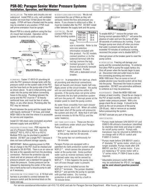
PlumbIng: Fasten 17-0012-01 plumbing kit<br />
onto the PST (pressure storage tank) with the<br />
pressure switch on the system-side of the PST<br />
and the hose barb on the pump-side of the PST<br />
as shown above. To aid in initial priming, pour<br />
water into the pump inlet before connecting<br />
hoses to the pump. Plumbing between the<br />
pump and the PST must be 1� ID heavily<br />
reinforced hose, and must be free of valves,<br />
filters, or any other device. Plumbing after the<br />
PST may be reduced.<br />
Plumb between the pump and the supply tank<br />
with heavily reinforced 1� ID hose, and install<br />
WSB-1000 in the inlet line where it is accessible<br />
for service and inspection.<br />
Install CV-100 check valve (included) anywhere<br />
between supply tank and NOFLO�.<br />
PREssuRE stoRagE tanK: <strong>PSR</strong> requires the<br />
use of a <strong>Pressure</strong> Storage Tank. Use only<br />
GROCO� PST-2, PST-3, PST-4 or PST-5.<br />
Multiple PSTs may be plumbed in parallel if<br />
desired. DO NOT use a single PST-1 because it<br />
does not have sufficient storage capacity.<br />
IMPORTANT: Before applying power to <strong>PSR</strong>,<br />
the air charge in the PST must be checked and<br />
adjusted to 28-30 PSIG. There is an air valve on<br />
the tank at the opposite end from the plumbing<br />
connection. Remove the protective cap and<br />
check and set air pressure with no water<br />
pressure present; use a standard tire gauge to<br />
check the pressure. Excess pressure can be<br />
released by depressing the center of the valve.<br />
Use a hand pump such a bicycle pump to add<br />
air if necessary.<br />
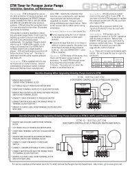
PREssuRE swItch connEctIon: A 10-foot wire<br />
harness is provided to connect between the<br />
pressure switch and the terminal block on the<br />
motor end cap.<br />
watER FIltERs and PuRIFIERs: We do not<br />
recommend the use of filters as they will<br />
seriously restrict the flow and pressure you<br />
desire. If you choose to utilize such a filter, it<br />
must be installed after the PST. DO NOT install<br />
a filter between the supply tank and the pump.<br />
ElEctRIcal: Do not<br />
connect <strong>PSR</strong> to the<br />
boat’s bonding system.<br />
Voltage Breaker<br />
<strong>PSR</strong> 12V 50-A<br />
<strong>PSR</strong> 24V 30-A<br />
<strong>PSR</strong> 32V 20-A<br />
Proper<br />
wire<br />
size is essential. Refer to the<br />
wire size selection<br />
information included with<br />
this product. For <strong>DC</strong> models<br />
connect positive (+) to the<br />
solenoid terminal with the<br />
red tag (remove the tag).<br />
Connect ground (-) to the<br />
bronze stud directly beneath<br />
the solenoid. Protect<br />
<strong>PSR</strong> with a dedicated circuit<br />
breaker.<br />
staRt-uP: In preparation for start-up, check<br />
all plumbing and electrical connections.<br />
Open all faucets and shower heads half-way.<br />
Apply power at the circuit breaker; the pump<br />
will run and should self-prime within 30<br />
seconds. If the pump does not prime within<br />
30-seconds the dry-tank protection system<br />
will turn the pump off. Interrupt power at the<br />
breaker panel to reset the pump control.<br />
As water flows smoothly from each shower<br />
head and faucet, shut it off. When all outlets<br />
have been shut off the pump will pressurize<br />
the system and shut off. Note that it will take<br />
several minutes to fill the PST(s) and the<br />
water heater(s).<br />
dRy tanK shut-down: These are the drytank<br />
conditions under which your <strong>Paragon</strong><br />
Pump will turn off.<br />
* NOFLO� has sensed the absence of water<br />
at the pump inlet for 30-seconds<br />
* The pump has run continuously for<br />
10-minutes<br />
<strong>Paragon</strong> Pumps are equipped with a<br />
patented dry tank protection system called<br />
NOFLO�, which senses the presence of<br />
water at the pump inlet. Some purified<br />
water such as reverse-osmosis water or<br />
reclaimed water may not be sensed by<br />
NOFLO�. If this happens the pump may<br />
turn off even though water is present.<br />
A jumper wire is installed across the<br />
NOFLO� terminals. The jumper disables<br />
NOFLO� and permits the pump to operate<br />
with purified waters. Dry running<br />
protection is still provided by a built-in<br />
10-minute timer.<br />
Info sheet PsR-dc, 1 of 2<br />
120221<br />
To enable NOFLO� remove the jumper wire.<br />
During normal operation NOFLO� will sense the<br />
absence of water and turn the pump off after<br />
30-seconds of continuous dry running. If your<br />
<strong>Paragon</strong> pump ever shuts off when you know<br />
that water is present and the pump has not<br />
exceeded 10-minutes of continuous running,<br />
reconnect the jumper wire to disable NOFLO�.<br />
Interrupt power at the breaker panel to reset the<br />
pump control.<br />
wIntERIzatIon: Freezing will damage your<br />
pump and the connected plumbing. To winterize<br />
first allow <strong>PSR</strong> to pump the supply tank(s) dry.<br />
Shut off power when the faucets begin to pass<br />
air. Disconnect inlet and outlet hoses to drain<br />
the connecting plumbing and remove<br />
WSB-1000 bowl. Pour an ounce or two of<br />
potable alcohol (your favorite scotch will do fine)<br />
into the pump. Reconnect the hoses to prevent<br />
evaporation. DO NOT use automotive antifreeze<br />
to winterize as it may be poisonous.<br />
maIntEnancE: Check the WSB-1000 inlet<br />
strainer at least monthly. Check the air charge in<br />
the PST at least monthly. This is done with no<br />
system water pressure present. With a tire<br />
gauge check the air charge. It should be the<br />
same as the cut-on pressure of the pump<br />
(28-30 psi). Add or remove air as needed<br />
before pressurizing the system.<br />
DO NOT lubricate any part of the pump.<br />
sERvIcE notEs:<br />
* Pumps made between S/N 030101-01 and<br />
030615-99 utilized a transducer (identified<br />
by stainless steel body and plug-in cable)<br />
for on/off pump control. Pumps with<br />
transducer may be returned to GROCO for<br />
no-charge refit of IPS-51 switch and<br />
P-6001-E Control.<br />
* Pumps made before S/N 880101 used a<br />
4� diameter �G� series motor, which is no<br />
longer available. Pumps made after S/N<br />
880101 use the �J� series motor. If you<br />
are replacing a �G� series motor with a<br />
�J� series motor, P-7004-D base is also<br />
required.<br />
* Adjustable pressure switch #69-A<br />
may be substituted for IPS-51, but must<br />
not be used aboard gasoline-powered<br />
boats.<br />
For service assistance/information call 410.712.4242 and ask for <strong>Paragon</strong> Service Department. After hours, go to www.groco.net.
� 1999 GROSS MEChANICAL LABORATORIES, INC. ALL RIGhTS RESERVED.<br />
<strong>PSR</strong>-<strong>DC</strong>: <strong>Paragon</strong> <strong>Senior</strong> <strong>Water</strong> <strong>Pressure</strong> <strong>Systems</strong><br />
Installation, Operation, and Maintenance<br />
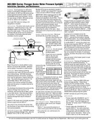
Item Part number description Qty Regular master<br />
1 P-9020-C End Cap, after 030801 1<br />
P-9020 End Cap, before 030801 1<br />
2 P-9015 Seal 2 * *<br />
3 P-9001/9002 Set Pump housings 1<br />
4 2-042 O-Ring, after 851201 1 * *<br />
2-041 O-Ring, before 851201 1 * *<br />
5 P-9009 Set Bearings 1<br />
6 P-9014 Set Impellers 1 *<br />
7 P-9003/4 Assy Shaft & Eccentrics 1<br />
8 P-9006 Separator Assy 1<br />
9 1428X12hS Screw 4<br />
1-9 P-9000 Pump Assy 1<br />
10 P-7006 Spyder only 1 * *<br />
11 P-7005 Coupling Set 1<br />
12 P-7004-D Base 1<br />
13 (Voltage)-JCE Motor & Control Assy 1<br />
14 (Voltage)-J Motor only 1<br />
15 P-6001-A Control before 880101 (NLA) 1<br />
P-6001-B Control 880101-020630 (NLA)<br />
P-6001-D Control 030101-030619 (NLA)<br />
P-6001-E Control after 020101<br />
16 P-6003 (Voltage) Solenoid only 1<br />
17 17-0007-05 Plumbing Kit, Outlet 1<br />
18 CV-75 Check Valve only 1<br />
P-9021-E (NLA)<br />
19 PVC-33 3/4” Sch-80 PVC Nipple 1<br />
20 NOFLO7500 Dry Tank Module only 1<br />
21 17-0012-01 Remote Plumbing Kit 1<br />
22 IPS-51 <strong>Pressure</strong> Switch, UL & CE 1<br />
69-A <strong>Pressure</strong> Switch, not UL & CE<br />
23 P-8005-B Oil Filed Guage 1<br />
P-8005-A Gauge (not oil filled) (NLA)<br />
NS P-9005 Seal, before 850101 2 * *<br />
NS WSA-1001 Filter Basket 1 *<br />
NS WSA-1002 Gasket 1 *<br />
NS P-9007 Impeller Guide only (NLA) 1<br />
NS P-9022-B Mount Feet (4) 1<br />
<strong>PSR</strong> Regular Service Kit *<br />
<strong>PSR</strong> Master Service Kit *<br />
Info sheet PsR-dc, 2 of 2<br />
120221<br />
Dry-Tank<br />
ConTrol# on/off ProTeCTion CommenT<br />
P-6001-A <strong>Pressure</strong> Thermal NLA - see individual parts<br />
Switch Switch<br />
P-6001-B <strong>Pressure</strong> Thermal Between S/N 880101-020630<br />
Switch Switch NLA - See P-6001-E<br />
P-6001-D Transducer NOFLO� + Between 030101-01 and<br />
Timer 300615-99 (no longer available)<br />
P-6001-E <strong>Pressure</strong> NOFLO� + After S/N 020101<br />
Switch Timer<br />
For service assistance/information call 410.712.4242 and ask for <strong>Paragon</strong> Service Department. After hours, go to www.groco.net.