Hydromatic HSE Series Self-Cleaning Raw Water Strainers - Groco
Hydromatic HSE Series Self-Cleaning Raw Water Strainers - Groco
Hydromatic HSE Series Self-Cleaning Raw Water Strainers - Groco

You also want an ePaper? Increase the reach of your titles
YUMPU automatically turns print PDFs into web optimized ePapers that Google loves.
<strong>Hydromatic</strong> <strong>HSE</strong> <strong>Series</strong> <strong>Self</strong>-<strong>Cleaning</strong> <strong>Raw</strong> <strong>Water</strong> <strong>Strainers</strong><br />
Installation, Operation, and Maintenance<br />
Info Sheet <strong>HSE</strong> <strong>Series</strong>, 1 of 4<br />
091010<br />
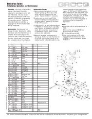
The Concept: For as long<br />
as raw water strainers have<br />
been used to filter debris<br />
from raw water flow to<br />
engines and equipment,<br />
there has been the need to<br />
periodically shut down the<br />
system for filter basket<br />
cleaning. <strong>Hydromatic</strong> raw<br />
water strainers eliminate<br />
this task by periodically<br />
performing a 30-second self-cleaning cycle<br />
during which a powerful macerator grinds and<br />
discharges accumulated debris and discharges it<br />
overboard.<br />
<strong>Hydromatic</strong> can serve as a sea-chest by<br />
providing filtered water to multiple consumers,<br />
such as main engines, A/C units, generators,<br />
water-makers, and refrigeration units. Plumbing<br />
and maintenance are simplified, and installation<br />
time and materials cost are reduced.<br />
Installation Considerations: Two installation<br />
plumbing scenarios are possible - below<br />
waterline discharge or above waterline<br />
discharge. Either installation will function well;<br />
but more stringent installation parameters must<br />
be met for an above waterline discharge<br />
installation.<br />
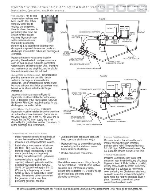
Below <strong>Water</strong>line Discharge (Figure-1):<br />
<strong>Hydromatic</strong> must be installed below the waterline.<br />
A dedicated 1" full-flow seacock (GROCO<br />
BV-1000 or FBV-1000) must be installed for the<br />
discharge of macerated debris.<br />
Above <strong>Water</strong>line Discharge (Figure-2):<br />
<strong>Hydromatic</strong> must be installed below the waterline.<br />
An in-line check valve is required (same size as<br />
the water supply line) in the A/C raw water line to<br />
ensure that the A/C water supply line is not<br />
drained by the greater flow to other consumers, or<br />
by the discharge from <strong>Hydromatic</strong>.<br />
© 1999 GROSS MECHANICAL LABORATORIES, INC. ALL RIGHTS RESERVED.<br />
General Strainer Installation Notes:<br />
* Install <strong>Hydromatic</strong> below the waterline, at<br />
or near the vessel centerline. Vessel<br />
movement will change waterline location.<br />
* Install a large low-pressure hull strainer<br />
(GROCO RSC) over the inlet thru-hull<br />
fitting to reduce the possibility of large<br />
debris (plastic bag or a large leaf)<br />
blocking the water supply to <strong>Hydromatic</strong>.<br />
* A solenoid valve is required (not<br />
supplied) between <strong>Hydromatic</strong> and the<br />
generator raw water pump. GROCO<br />
SV-75 (3/4")(specify voltage) or SV-100<br />
(1")(specify voltage) may be ordered.<br />
Check GROCO for availability of larger<br />
sizes. The solenoid valve closes when<br />
the generator is not in use, thus<br />
preventing generator flooding.<br />
* Avoid sharp hose bends and sags, and<br />
keep hose runs at minimum length.<br />
* <strong>Hydromatic</strong> may be oriented horizon-tally<br />
or vertically, but the inlet must remain<br />
below waterline at all times.<br />
* Double-clamp hose connections.<br />
Plumbing:<br />
Use full-flow seacocks and fittings throughout<br />
the installation. GROCO offers full flow<br />
seacocks from 3/4" through 5" sizes.<br />
Bronze flange adaptors (4", 5" and 6" flange<br />
to NPT) are also offered to simplify<br />
plumbing connections.<br />
Operator Panel Installation:<br />
Choose a location that will enable you to<br />
monitor and adjust system operation,<br />
probably at the helm. The panel fits into a<br />
2-11/16" high x 3-7/8" wide wall cutout. Do<br />
not fasten the panel to the wall at this time.<br />
Control Box Installation:<br />
Install the Control Box (gray water-tight<br />
enclosure) near the strainer/pump unit, above<br />
bilge water level. A 10-foot cable is provided,<br />
already connected to the motor. Secure the<br />
power pack to a bulkhead by removing its<br />
cover and using four (4) stainless steel wood<br />
screws to fasten the enclosure through the<br />
same holes that hold the enclosure cover in<br />
place. Leave the cover off until power<br />
connections have been made.<br />
For service assistance/information call 410.604.3800 and ask for <strong>Strainers</strong> Service Department. After hours go to www.groco.net.
<strong>Hydromatic</strong> <strong>HSE</strong> <strong>Series</strong> <strong>Self</strong>-<strong>Cleaning</strong> <strong>Raw</strong> <strong>Water</strong> <strong>Strainers</strong><br />
Installation, Operation, and Maintenance<br />
Info Sheet <strong>HSE</strong> <strong>Series</strong>, 2 of 4<br />
091010<br />
© 1999 GROSS MECHANICAL LABORATORIES, INC. ALL RIGHTS RESERVED.<br />
ELECTRICAL CONNECTIONS<br />
General Note:<br />
Turn o ff AC and DC power before installing or<br />
servicing <strong>Hydromatic</strong>.<br />
* <strong>Hydromatic</strong> is shipped with the Control Box<br />
TEMPORARILY fastened to the motor mount<br />
bracket. If you want to permanently mount the<br />
control box to the motor, fasten a plate the<br />
motor bracket that will accept mounting<br />
screws from the control box. The control box<br />
is supplied with a 10-foot cable to allow for<br />
remote mounting.<br />
* Run the ring connector end of the 100-foot<br />
cable from the <strong>Hydromatic</strong> location to the<br />
operator panel location.<br />
* Make operator panel connections in<br />
accordance with the schematic (Figures-4, 5,<br />
6, 7, 8 or 9) showing the "consumer" option<br />
you have selected.<br />
There are four possible "Consumer" options for<br />
<strong>Hydromatic</strong> operation. IMPORTANT: Choose<br />
only one.<br />
Option-1. (Figure-4) <strong>Cleaning</strong> cycle determined by<br />
timer only.<br />
Option-2. <strong>Cleaning</strong> cycle determined by operation<br />
of DC consumer only (engine or generator)<br />
Method-A (Figure-5): Consumer detect signal<br />
from switched DC (-) source<br />
Method-B (Figure-6): Consumer detect signal<br />
from switched DC (+) source<br />
Option-3. (Figure-7) <strong>Cleaning</strong> cycle determined<br />
by operation of AC consumer only (air<br />
conditioner)<br />
Option-4. <strong>Cleaning</strong> cycle determined by<br />
operation of either AC and/or DC consumer,<br />
whichever is operating<br />
Method-A (Figure-8): DC consumer detect from<br />
DC (-)<br />
Method-B (Figure-9): DC consumer detect from<br />
DC (+)<br />
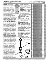
OPTION-1 (FIGURE-4):<br />
* Jumpers are provided on the operator<br />
panel pcb between terminals 7 & 3, and<br />
between terminals 6 & 4. With both<br />
jumpers installed cleaning cycles will<br />
occur at the longest illuminated interval<br />
115VAC Power Connection:<br />
<strong>HSE</strong> 115VAC requires a dedicated<br />
15-amp circuit breaker. Turn off power<br />
at the breaker before making power<br />
connections.<br />
Run 12-gauge 3-conductor insulated<br />
cable to the Control Box. Remove the<br />
Control Box cover and feed the cable<br />
through the strain relief flexible<br />
connector. Use #6 ring terminals for<br />
12-gauge wire to connect power to the<br />
terminal block as follows:<br />
Green = Ground, Position 4<br />
Black = Line, Position 5<br />
White = Neutral, Position 6<br />
Replace and secure cover.<br />
FIGURE-4<br />
showing on the touchpad. Choose a 5,<br />
15, 30 or 60-minute interval.<br />
* Plug the connectorized end of the 100-<br />
foot cable to the control box.<br />
230VAC Power Connection:<br />
<strong>HSE</strong> 230VAC requires a dedicated<br />
10-amp circuit breaker. Turn off power<br />
at the breaker before making power<br />
connections.<br />
Run 12-gauge 3-conductor insulated<br />
cable to the Control Box. Remove the<br />
Control Box cover and feed the cable<br />
through the strain relief flexible<br />
connector. Use #6 ring terminals for<br />
12-gauge wire to connect power to the<br />
terminal block as follows:<br />
Green = Ground, Position 4<br />
Black = Line A, Position 5<br />
White = Line B, Position 6<br />
Replace and secure cover.<br />
For service assistance/information call 410.604.3800 and ask for <strong>Strainers</strong> Service Department. After hours go to www.groco.net.
<strong>Hydromatic</strong> <strong>HSE</strong> <strong>Series</strong> <strong>Self</strong>-<strong>Cleaning</strong> <strong>Raw</strong> <strong>Water</strong> <strong>Strainers</strong><br />
Installation, Operation, and Maintenance<br />
Info Sheet <strong>HSE</strong> <strong>Series</strong>, 3 of 4<br />
091010<br />
© 1999 GROSS MECHANICAL LABORATORIES, INC. ALL RIGHTS RESERVED.<br />
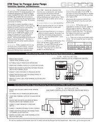
Option-2, Method-A (Figure-5):<br />
* Identify a NO (normally open) switched DC (-)<br />
output, such as an oil pressure sender or fuel<br />
pump input. With 18-gauge (or larger) marine<br />
grade stranded copper wire, make a<br />
connection between this signal and operator<br />
panel Terminal-4.<br />
* Jumpers are provided on the operator panel<br />
pcb between terminals 7 & 3, and between<br />
terminals 6 & 4. Remove the jumper between<br />
6 & 4. With only the 7-3 jumper installed<br />
cleaning cycles will occur at the longest<br />
illuminated interval showing on the touchpad,<br />
but only when the connected DC consumer<br />
(engine or generator) is operating. Choose a<br />
5, 15, 30 or 60-minute interval.<br />
* Plug the connectorized end of the 100-foot<br />
cable to the control box.<br />
Option-2, Method-B (Figure-6):<br />
* Identify a NO (normally open) switched DC (+)<br />
output, such as an oil pressure sender or fuel<br />
pump input. With 18-gauge (or larger) marine<br />
grade stranded copper wire, make a<br />
connection between this signal and operator<br />
panel Terminal-3.<br />
* Jumpers are provided on the operator panel<br />
pcb between terminals 7 & 3, and between<br />
terminals 6 & 4. Remove the jumper between<br />
7 & 3. With only the 6-4 jumper installed<br />
cleaning cycles will occur at the longest<br />
illuminated interval showing on the touchpad,<br />
but only when the connected DC consumer<br />
(engine or generator) is operating. Choose a<br />
5, 15, 30 or 60-minute interval.<br />
* Plug the connectorized end of the 100-foot<br />
cable to the control box.<br />
Option-3 (Figure-7):<br />
* Identify the switched AC input to the air<br />
conditioner motor. With 18-gauge (or larger)<br />
marine grade stranded copper wire, make a<br />
connection between this input (line and neutral)<br />
and operator panel Terminals-1 and 2.<br />
* Jumpers are provided on the operator panel<br />
pcb between terminals 7 & 3, and between<br />
terminals 6 & 4. Remove both jumpers.<br />
<strong>Cleaning</strong> cycles will occur at the longest<br />
illuminated interval showing on the touchpad,<br />
but only when the connected AC consumer (air<br />
conditioner) is operating. Choose a 5, 15, 30<br />
or 60-minute interval.<br />
* Plug the connectorized end of the 100-foot<br />
cable to the control box<br />
FIGURE-5<br />
FIGURE-6<br />
FIGURE-7<br />
For service assistance/information call 410.604.3800 and ask for <strong>Strainers</strong> Service Department. After hours go to www.groco.net.
<strong>Hydromatic</strong> <strong>HSE</strong> <strong>Series</strong> <strong>Self</strong>-<strong>Cleaning</strong> <strong>Raw</strong> <strong>Water</strong> <strong>Strainers</strong><br />
Installation, Operation, and Maintenance<br />
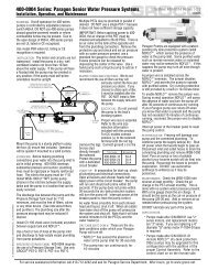
Option-4, Method-A (Figure-8):<br />
* Make AC consumer and DC consumer operator panel<br />
connections in accordance with Figure-8.<br />
* Identify a NO (normally open) switched DC (-) output<br />
(i.e., oil pressure sender). With 18-gauge (or larger)<br />
marine grade stranded copper wire, make a connection<br />
between this signal and operator panel Terminal-4.<br />
* Jumpers are provided on the operator panel pcb<br />
between terminals 7 & 3, and terminals 6 & 4.<br />
Remove the jumper between 6 & 4. With only the<br />
3-7 jumper installed cleaning cycles will occur at the<br />
longest illuminated interval showing on the touchpad,<br />
but only when one of the connected AC or DC<br />
consumers (engine, generator or air conditioner) is<br />
operating. Choose a 5, 15, 30 or 60-minute interval.<br />
* Plug the connectorized end of the 100-foot cable to the<br />
control box.<br />
Option-4, Method-B (Figure-9):<br />
* Make AC consumer and DC consumer operator panel<br />
connections in accordance with Figure-9.<br />
* Identify a NO (normally open) switched DC (+) output<br />
such as an oil pressure sender. With 18-gauge (or<br />
larger) marine grade stranded copper wire, make a<br />
connection between this signal and operator panel<br />
Terminal-3.<br />
* Jumpers are provided on the operator panel pcb<br />
between terminals 7 & 3, and terminals 6 & 4.<br />
Remove the jumper between 7 & 3. With only the 4-6<br />
jumper installed cleaning cycles will occur at the<br />
longest illuminated interval showing on the touch-pad,<br />
but only when one of the connected AC or DC<br />
consumers (engine, generator or air conditioner) is<br />
operating. Choose a 5, 15, 30 or 60-minute interval.<br />
* Plug the connectorized end of the 100-foot cable to the<br />
control box.<br />
FIGURE-8<br />
FIGURE-9<br />
Info Sheet <strong>HSE</strong> <strong>Series</strong>, 4 of 4<br />
091010<br />
© 1999 GROSS MECHANICAL LABORATORIES, INC. ALL RIGHTS RESERVED.<br />
OPERATION<br />
The operator panel has two control buttons, "CLEAN" and "SET", and several<br />
indicator lamps. Their functions are as follows:<br />
Button Lamp Function<br />
Clean<br />
Initiates a 30-second cleaning cycle if power is on<br />
Set<br />
Permits the selection of cleaning cycle interval<br />
Select a 5, 15, 30 or 60-minute interval<br />
<strong>Cleaning</strong> Indicates that a cleaning cycle is in process<br />
Consumer Indicates that one or more consumers is in operation<br />
Interval Indicates the current interval selection<br />
None Indicates that the unit is off<br />
* Each time power is applied,<br />
<strong>Hydromatic</strong> conducts a self-test<br />
routine, after which 30-second<br />
cleaning cycles will be repeated at<br />
the interval you have selected. To<br />
select an interval, press the SET<br />
button until the desired interval is<br />
displayed.<br />
* A cleaning cycle may be commanded<br />
at any time by pressing the CLEAN<br />
button.<br />
* On the side of the Control Box is a<br />
terminal block. If you wish to override<br />
the cleaning interval indicated by the<br />
operator panel to command a onetime<br />
clean cycle, connect a<br />
momentary switch to the terminal<br />
block. Actuating the momentary<br />
switch will perform the same function<br />
as pressing the CLEAN button on the<br />
operator panel.<br />
MAINTENANCE<br />
Turn off AC and DC power before servicing. Close<br />
inlet and discharge seacocks.<br />
* No regular maintenance is required, though<br />
occasional inspection of the filter basket is<br />
recommended.<br />
* To inspect the filter basket, disconnect power and<br />
unscrew the cover.<br />
* The four cutters secured to the impeller are not<br />
intended to be knife-sharp. With power to<br />
<strong>Hydromatic</strong> turned off, visually inspect them for<br />
wear; they should extend slightly above the impeller<br />
surface.<br />
* To replace the shaft seal the impeller must be<br />
removed. Unscrew the impeller. (This is a left-hand<br />
thread).<br />
* Install a new shaft seal carefully. The seal<br />
components are delicate and can be scratched;<br />
scratched components will not seal. Push seal<br />
components gently but firmly into place. First install<br />
the rubber cup with ceramic facing away from the<br />
motor; then install carbon with smooth surface<br />
facing ceramic. The spring tensions the assembly<br />
after the impeller is reinstalled.