Hydromatic HSE Series Self-Cleaning Raw Water Strainers - Groco
Hydromatic HSE Series Self-Cleaning Raw Water Strainers - Groco
Hydromatic HSE Series Self-Cleaning Raw Water Strainers - Groco

Create successful ePaper yourself
Turn your PDF publications into a flip-book with our unique Google optimized e-Paper software.
<strong>Hydromatic</strong> <strong>HSE</strong> <strong>Series</strong> <strong>Self</strong>-<strong>Cleaning</strong> <strong>Raw</strong> <strong>Water</strong> <strong>Strainers</strong><br />
Installation, Operation, and Maintenance<br />
Info Sheet <strong>HSE</strong> <strong>Series</strong>, 2 of 4<br />
091010<br />
© 1999 GROSS MECHANICAL LABORATORIES, INC. ALL RIGHTS RESERVED.<br />
ELECTRICAL CONNECTIONS<br />
General Note:<br />
Turn o ff AC and DC power before installing or<br />
servicing <strong>Hydromatic</strong>.<br />
* <strong>Hydromatic</strong> is shipped with the Control Box<br />
TEMPORARILY fastened to the motor mount<br />
bracket. If you want to permanently mount the<br />
control box to the motor, fasten a plate the<br />
motor bracket that will accept mounting<br />
screws from the control box. The control box<br />
is supplied with a 10-foot cable to allow for<br />
remote mounting.<br />
* Run the ring connector end of the 100-foot<br />
cable from the <strong>Hydromatic</strong> location to the<br />
operator panel location.<br />
* Make operator panel connections in<br />
accordance with the schematic (Figures-4, 5,<br />
6, 7, 8 or 9) showing the "consumer" option<br />
you have selected.<br />
There are four possible "Consumer" options for<br />
<strong>Hydromatic</strong> operation. IMPORTANT: Choose<br />
only one.<br />
Option-1. (Figure-4) <strong>Cleaning</strong> cycle determined by<br />
timer only.<br />
Option-2. <strong>Cleaning</strong> cycle determined by operation<br />
of DC consumer only (engine or generator)<br />
Method-A (Figure-5): Consumer detect signal<br />
from switched DC (-) source<br />
Method-B (Figure-6): Consumer detect signal<br />
from switched DC (+) source<br />
Option-3. (Figure-7) <strong>Cleaning</strong> cycle determined<br />
by operation of AC consumer only (air<br />
conditioner)<br />
Option-4. <strong>Cleaning</strong> cycle determined by<br />
operation of either AC and/or DC consumer,<br />
whichever is operating<br />
Method-A (Figure-8): DC consumer detect from<br />
DC (-)<br />
Method-B (Figure-9): DC consumer detect from<br />
DC (+)<br />
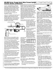
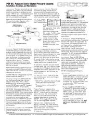
OPTION-1 (FIGURE-4):<br />
* Jumpers are provided on the operator<br />
panel pcb between terminals 7 & 3, and<br />
between terminals 6 & 4. With both<br />
jumpers installed cleaning cycles will<br />
occur at the longest illuminated interval<br />
115VAC Power Connection:<br />
<strong>HSE</strong> 115VAC requires a dedicated<br />
15-amp circuit breaker. Turn off power<br />
at the breaker before making power<br />
connections.<br />
Run 12-gauge 3-conductor insulated<br />
cable to the Control Box. Remove the<br />
Control Box cover and feed the cable<br />
through the strain relief flexible<br />
connector. Use #6 ring terminals for<br />
12-gauge wire to connect power to the<br />
terminal block as follows:<br />
Green = Ground, Position 4<br />
Black = Line, Position 5<br />
White = Neutral, Position 6<br />
Replace and secure cover.<br />
FIGURE-4<br />
showing on the touchpad. Choose a 5,<br />
15, 30 or 60-minute interval.<br />
* Plug the connectorized end of the 100-<br />
foot cable to the control box.<br />
230VAC Power Connection:<br />
<strong>HSE</strong> 230VAC requires a dedicated<br />
10-amp circuit breaker. Turn off power<br />
at the breaker before making power<br />
connections.<br />
Run 12-gauge 3-conductor insulated<br />
cable to the Control Box. Remove the<br />
Control Box cover and feed the cable<br />
through the strain relief flexible<br />
connector. Use #6 ring terminals for<br />
12-gauge wire to connect power to the<br />
terminal block as follows:<br />
Green = Ground, Position 4<br />
Black = Line A, Position 5<br />
White = Line B, Position 6<br />
Replace and secure cover.<br />
For service assistance/information call 410.604.3800 and ask for <strong>Strainers</strong> Service Department. After hours go to www.groco.net.