Tensile force requirement for the straightening of wire with roller ...
Tensile force requirement for the straightening of wire with roller ...
Tensile force requirement for the straightening of wire with roller ...

Create successful ePaper yourself
Turn your PDF publications into a flip-book with our unique Google optimized e-Paper software.
Fig. 1<br />
<strong>Tensile</strong> <strong><strong>for</strong>ce</strong> <strong>requirement</strong> <strong>for</strong> <strong>the</strong><br />
<strong>straightening</strong> <strong>of</strong> <strong>wire</strong> <strong>with</strong> <strong>roller</strong><br />
<strong>straightening</strong> units<br />
Comparison<br />
<strong>of</strong> <strong>the</strong> tensile<br />
<strong><strong>for</strong>ce</strong> <strong>requirement</strong><br />
according<br />
to [3] and [4]<br />
<strong>with</strong> measured<br />
values<br />
TRENDS<br />
50 WIRE 3/2000<br />
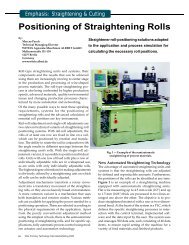
Marcus Paech<br />
Calculation specifications recommended <strong>for</strong> determining <strong>the</strong> tensile <strong><strong>for</strong>ce</strong> <strong>requirement</strong> <strong>for</strong> <strong>straightening</strong><br />
<strong>with</strong> <strong>roller</strong>-type <strong>straightening</strong> systems supply only rough approximations. A new model <strong>for</strong> calculating<br />
<strong>the</strong> tensile <strong><strong>for</strong>ce</strong> <strong>requirement</strong> was developed selectively on <strong>the</strong> basis <strong>of</strong> a <strong>requirement</strong>s pr<strong>of</strong>ile.<br />
It takes account <strong>for</strong> <strong>the</strong> first time <strong>of</strong> <strong>the</strong> <strong>straightening</strong> unit’s geometrical boundary conditions as well<br />
as <strong>the</strong> properties <strong>of</strong> <strong>the</strong> process material. Calculations carried out <strong>for</strong> an exemplary selection <strong>of</strong> <strong>wire</strong>s<br />
using <strong>the</strong> new model display a very good correlation <strong>with</strong> <strong>the</strong> measured values.<br />
Conventional and innovative technology<br />
[1, 2] <strong>for</strong> <strong>the</strong> <strong>straightening</strong> <strong>of</strong><br />
<strong>wire</strong> has a very large field <strong>of</strong> application,<br />
ranging from <strong>wire</strong> rolling mills<br />
and <strong>wire</strong> drawing plants to <strong>the</strong> manufacturers<br />
<strong>of</strong> finished and semi-finished<br />
<strong>wire</strong> products. Accordingly <strong>the</strong><br />
possibilities <strong>of</strong> working <strong>wire</strong> are numerous.<br />
Straightening units are employed<br />
not only as autonomous tools<br />
in higher-level processes but also as<br />
elements in machines <strong>for</strong> a variety <strong>of</strong><br />
purposes. Apart from producing<br />
straight <strong>wire</strong> <strong>the</strong>y are frequently used<br />
to create a defined residual bend.<br />
Whatever <strong>the</strong> details <strong>of</strong> <strong>the</strong> specific<br />
cases <strong>of</strong> application may be, <strong>the</strong>y all<br />
have one thing in common: <strong>the</strong> need<br />
to transport <strong>the</strong> process material relative<br />
to <strong>the</strong> <strong>straightening</strong> unit.<br />
Process design and <strong>the</strong> selective<br />
planning and construction <strong>of</strong> machinery<br />
are impossible <strong>with</strong>out an<br />
exact knowledge <strong>of</strong> <strong>the</strong> tensile <strong><strong>for</strong>ce</strong>s<br />
needed to transport <strong>the</strong> process material.<br />
Fact is, <strong>the</strong>se tensile <strong><strong>for</strong>ce</strong>s<br />
have a dominant influence on potential<br />
process speeds and on essential<br />
power ratings. And knowing <strong>the</strong>m<br />
can also have a positive effect when<br />
<strong>the</strong>y are used to optimize <strong>the</strong> consumption<br />
<strong>of</strong> energy per unit as laid<br />
down in <strong>the</strong> standards concerning<br />
environmental management systems,<br />
e.g. ISO 14000 ff.<br />
Analysis<br />
In spite <strong>of</strong> this need <strong>for</strong> knowledge <strong>of</strong><br />
<strong>the</strong> tensile <strong><strong>for</strong>ce</strong>s, today’s state <strong>of</strong> <strong>the</strong><br />
Fig. 2 Division <strong>of</strong> <strong>the</strong> cross section in elements<br />
art <strong>for</strong> <strong>the</strong>ir determination is limited<br />
to a few specific and expensive<br />
<strong>straightening</strong> tests and measurements<br />
or to calculations able to provide<br />
only rough tensile <strong><strong>for</strong>ce</strong> approximations.<br />
In [3], <strong>for</strong> example, <strong>the</strong>re is<br />
an explanation <strong>of</strong> how to calculate<br />
<strong>the</strong> greatest <strong><strong>for</strong>ce</strong> <strong>for</strong> drawing a <strong>wire</strong><br />
through a <strong>roller</strong> <strong>straightening</strong> unit<br />
<strong>with</strong> n <strong>roller</strong>s. Initial and residual<br />
bends <strong>of</strong> magnitudes corresponding<br />
to <strong>the</strong> reciprocal value <strong>of</strong> <strong>the</strong> <strong>roller</strong><br />
radius are presumed <strong>for</strong> all <strong>the</strong> (n-1)<br />
bending operations per<strong>for</strong>med. The<br />
solution applies <strong>for</strong> round <strong>wire</strong>s <strong>with</strong><br />
an ideal elastic-plastic material characteristic,<br />
a condition that is hardly<br />
relevant <strong>for</strong> <strong>the</strong> <strong>wire</strong>s used in practice.<br />
The contents <strong>of</strong> [3] are supplemented<br />
in [4] where an approxima-
tion in <strong>the</strong> <strong>for</strong>m <strong>of</strong> an arc is introduced<br />
<strong>for</strong> <strong>the</strong> bend <strong>of</strong> <strong>the</strong> process<br />
material in <strong>the</strong> area <strong>of</strong> influence <strong>of</strong> an<br />
active-bending <strong>roller</strong>. Account is taken<br />
<strong>for</strong> <strong>the</strong> first time ever <strong>of</strong> both <strong>the</strong><br />
pitch, i.e. <strong>the</strong> distance from one<br />
<strong>straightening</strong> <strong>roller</strong> to ano<strong>the</strong>r, and<br />
<strong>the</strong> <strong>roller</strong> adjustments, albeit <strong>for</strong> <strong>the</strong><br />
sole case <strong>of</strong> parallel adjustment in<br />
which all <strong>the</strong> <strong>roller</strong>s have identical<br />
adjustment values in relation to <strong>the</strong><br />
<strong>wire</strong>-specific zero line.<br />
Fig. 1 compares <strong>the</strong> results <strong>of</strong> tensile<br />
<strong><strong>for</strong>ce</strong> calculations according to<br />
[3] and [4] <strong>with</strong> <strong>the</strong> measured results<br />
<strong>for</strong> <strong>the</strong> <strong>straightening</strong> <strong>of</strong> selected <strong>wire</strong>s<br />
on a <strong>roller</strong>-type <strong>straightening</strong> unit.<br />
Table 1 and 2 lists <strong>the</strong> parameters <strong>of</strong><br />
<strong>the</strong> unit used and <strong>the</strong> properties <strong>of</strong><br />
<strong>the</strong> <strong>wire</strong>. Increasing <strong>the</strong> bend radius<br />
in <strong>the</strong> areas <strong>of</strong> influence <strong>of</strong> <strong>the</strong> activebending<br />
<strong>roller</strong>s in accordance <strong>with</strong><br />
[4] leads to a considerable reduction<br />
in <strong>the</strong> results <strong>of</strong> <strong>the</strong> calculated tensile<br />
<strong><strong>for</strong>ce</strong> compared to <strong>the</strong> results according<br />
to [3]. Table 2 shows <strong>the</strong> relative<br />
error εr <strong>of</strong> all <strong>the</strong> calculated results in<br />
relation to <strong>the</strong> measured results. The<br />
tensile <strong><strong>for</strong>ce</strong>s are always overestimated,<br />
also when proceeding in accordance<br />
<strong>with</strong> [4], <strong>with</strong> excessively large<br />
deviations occuring in particular <strong>for</strong><br />
<strong>the</strong> <strong>wire</strong>s A, D and E. Determining<br />
<strong>the</strong> tensile <strong><strong>for</strong>ce</strong> <strong>requirement</strong> in accordance<br />
<strong>with</strong> [3] is not recommended<br />
under any circumstances.<br />
Requirements<br />
From this short analysis <strong>of</strong> <strong>the</strong><br />
known options available <strong>for</strong> calculating<br />
<strong>the</strong> tensile <strong><strong>for</strong>ce</strong> it is possible to<br />
Fig. 3<br />
Approximation <strong>of</strong><br />
material behaviour<br />
under alternating<br />
load de<strong>for</strong>mation<br />
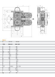
Table 1: Parameters <strong>of</strong> <strong>the</strong><br />
<strong>straightening</strong> system<br />
Straightening unit RB 11-3 CS<br />
Number <strong>of</strong> <strong>roller</strong>s n 11<br />
Outer ∅ <strong>of</strong> <strong>straightening</strong> <strong>roller</strong> DA [mm] 31<br />
Roller pr<strong>of</strong>ile groove width B [mm] 3.2<br />
Roller pr<strong>of</strong>ile groove angle α [°] 90<br />
Roller pitch T [mm] 19<br />
derive a clear picture <strong>of</strong> what is needed.<br />
Apart from being innovative and<br />
quicker than taking measurements,<br />
<strong>the</strong> solution should have <strong>the</strong> following<br />
features:<br />
– It must be possible to calculate <strong>the</strong><br />
tensile <strong><strong>for</strong>ce</strong> <strong>for</strong> any <strong>straightening</strong><br />
unit, <strong>with</strong> due account taken <strong>of</strong> its<br />
geometrical boundary conditions<br />
such as number <strong>of</strong> <strong>roller</strong>s, <strong>roller</strong><br />
diameter, <strong>roller</strong> pr<strong>of</strong>ile, pitch and<br />
adjustments.<br />
– Regardless <strong>of</strong> <strong>the</strong> method <strong>of</strong> adjustment<br />
it must be possible to achieve<br />
calculated results <strong>with</strong> a relative error<br />
in <strong>the</strong> range <strong>of</strong> –10% ≤ εr ≤ 10%<br />
in relation to <strong>the</strong> corresponding<br />
measured values.<br />
– The initial bend range or initial<br />
bend and <strong>the</strong> required residual<br />
bend have to be included in <strong>the</strong><br />
problem-solving procedure.<br />
– Each bending operation is decisively<br />
affected by <strong>the</strong> de<strong>for</strong>mation<br />
characteristic <strong>of</strong> <strong>the</strong> specific material,<br />
hence it is necessary to integrate<br />
a capable material model.<br />
– Exact determination <strong>of</strong> <strong>the</strong> process<br />
material’s bending line in correlation<br />
<strong>with</strong> <strong>the</strong> bend characteris-<br />
Fig. 4<br />
Bending moment/<br />
bend curves<br />
Table 2: Parameters <strong>of</strong> selected <strong>wire</strong>s and relative error in<br />
<strong>for</strong>ecasts <strong>of</strong> tensile <strong><strong>for</strong>ce</strong>s<br />
Wire A B C D<br />
Wire ∅ d [mm] 1.55 2.00 1.5 1.9<br />
Yield limit Rp [MPa] 725 1000 2110 1800<br />
Modulus <strong>of</strong> elasticity E [MPa] 190190 181380 199880 188720<br />
Initial bend κ*a [ – ] -0.7 -0.6 -0.26 -0.33<br />
Relative error εr <strong>for</strong> tensile [%]<br />
<strong><strong>for</strong>ce</strong> according to [3] 366 293 755 559<br />
Relative error εr <strong>for</strong> tensile [%]<br />
<strong><strong>for</strong>ce</strong> according to [4] 33 9 33 44<br />
tic is an important condition <strong>for</strong><br />
calculating <strong>the</strong> tensile <strong><strong>for</strong>ce</strong>; o<strong>the</strong>rwise<br />
it is impossible to identify <strong>the</strong><br />
exact moments at <strong>the</strong> active-bending<br />
<strong>roller</strong>s.<br />
– Considering <strong>the</strong> large assortment<br />
<strong>of</strong> material cross sections, it has to<br />
be possible to calculate <strong>the</strong> tensile<br />
<strong><strong>for</strong>ce</strong> not only <strong>for</strong> round <strong>wire</strong> but<br />
<strong>for</strong> any cross sections.<br />
Model<br />
Central element <strong>of</strong> <strong>the</strong> calculation<br />
model <strong>for</strong> tensile <strong><strong>for</strong>ce</strong> from Witels-<br />
Albert is <strong>the</strong> analysis <strong>of</strong> a <strong>wire</strong> section<br />
on its way through <strong>the</strong> <strong>of</strong>fset<br />
<strong>roller</strong> arrangement <strong>of</strong> a <strong>straightening</strong><br />
unit in <strong>the</strong> light <strong>of</strong> <strong>the</strong> pre-given <strong>requirement</strong><br />
pr<strong>of</strong>ile. Under <strong>the</strong> influence<br />
<strong>of</strong> alternating bends, <strong>the</strong> bend<br />
<strong>of</strong> <strong>the</strong> <strong>wire</strong> section changes from<br />
<strong>roller</strong> to <strong>roller</strong> in <strong>the</strong> direction <strong>of</strong> <strong>the</strong><br />
exit. A bending moment is assigned<br />
to each bend. The relationship between<br />
<strong>the</strong> bending moment and <strong>the</strong><br />
bend is defined by <strong>the</strong> material and<br />
<strong>the</strong> cross sectional geometry <strong>of</strong> <strong>the</strong><br />
process material and by <strong>the</strong> respective<br />
geometrical boundary condi-<br />
3/2000 WIRE 51
TRENDS<br />
52 WIRE 3/2000<br />
tions. The work <strong>of</strong> de<strong>for</strong>mation,<br />
which plays a dominant role in <strong>the</strong><br />
tensile <strong><strong>for</strong>ce</strong> needed to transport <strong>the</strong><br />
process material, is derived from <strong>the</strong><br />
relationship between bending moment<br />
and bend <strong>for</strong> each bending<br />
operation. Dynamic contents – caused<br />
by <strong>the</strong> <strong><strong>for</strong>ce</strong>s and moments <strong>of</strong> mass<br />
inertia – and frictional contents are<br />
small and disregarded accordingly.<br />
Bending moments and bends<br />
A bending operation i in which <strong>the</strong><br />
<strong>wire</strong> section is loaded and unloaded<br />
takes place in <strong>the</strong> area <strong>of</strong> influence <strong>of</strong><br />
a <strong>straightening</strong> <strong>roller</strong>. The load can<br />
result in an elastic or an elastic-plastic<br />
de<strong>for</strong>mation and is characterized<br />
by <strong>the</strong> initial state [i0] and <strong>the</strong> loading<br />
maximum [iv]. The loading is<br />
followed – starting from <strong>the</strong> loading<br />
maximum [iv] – by unloading to <strong>the</strong><br />
final state [(i+1)0], which at <strong>the</strong> same<br />
time represents <strong>the</strong> initial state <strong>of</strong> <strong>the</strong><br />
next bending operation. The characteristic<br />
variables <strong>of</strong> <strong>the</strong> <strong>wire</strong> section<br />
such as strain, stress, bend and bending<br />
moment change from <strong>the</strong> start <strong>of</strong><br />
<strong>the</strong> loading to <strong>the</strong> end <strong>of</strong> <strong>the</strong> unloading.<br />
A bending moment/bend<br />
curve <strong>for</strong> a bending operation i is a<br />
determinate representation <strong>of</strong> <strong>the</strong><br />
bend κi at <strong>the</strong> bending moment Mi<br />
(Equation 1).<br />
M i = f ( κi<br />
)<br />
Eq. 1<br />
For <strong>the</strong> numerical generation <strong>of</strong><br />
bending moment/bend curves <strong>for</strong> all<br />
bend operations i it is necessary to<br />
know <strong>the</strong> corresponding bend <strong>of</strong> <strong>the</strong><br />
loading maximum. [5] reports on an<br />
algorithm <strong>for</strong> calculating <strong>the</strong> bending<br />
line <strong>of</strong> <strong>the</strong> process material between<br />
<strong>the</strong> individual <strong>straightening</strong><br />
<strong>roller</strong>s, which at <strong>the</strong> same time also<br />
supplies <strong>the</strong> reference adjustment-related<br />
bends κ*iv <strong>for</strong> <strong>the</strong> loading maximums,<br />
provided <strong>the</strong> reference initial<br />
bend κ*a = κ*10 <strong>of</strong> <strong>the</strong> process material<br />
is given.<br />
The advantage <strong>of</strong> using reference<br />
variables, which are always marked<br />
<strong>with</strong> an asterisk, is that it simplifies<br />
<strong>the</strong> modeling. Equation 2 states, <strong>for</strong><br />
example, that <strong>the</strong> reference bend κ*iv<br />
<strong>of</strong> <strong>the</strong> reference strain <strong>of</strong> <strong>the</strong> outer<br />
fibers <strong>of</strong> <strong>the</strong> process material equals<br />
ε*iav. From <strong>the</strong> reference bend or<br />
strain it is possible – <strong>with</strong> <strong>the</strong> strain<br />
limit Rp and <strong>the</strong> modulus <strong>of</strong> elasticity<br />
E – to calculate <strong>the</strong> strain <strong>of</strong> <strong>the</strong> outer<br />
fiber εiav in <strong>the</strong> non-referenced representation.<br />
With <strong>the</strong> cross section<br />
height H it is possible at any time to<br />
derive <strong>the</strong> bend radius riv correlating<br />
<strong>with</strong> <strong>the</strong> strain ε*iv .<br />
κ*<br />
iv<br />
= ε<br />
Table 3: Calculation <strong>of</strong> total tensile <strong><strong>for</strong>ce</strong> <strong>requirement</strong> FZR<br />
*<br />
iv<br />
= ε<br />
*<br />
iav<br />
E⋅ε<br />
iav E⋅<br />
H<br />
= =<br />
Eq. 2<br />
R p 2⋅<br />
R p ⋅riv<br />
Calculating a bending moment/bend<br />
curve requires <strong>the</strong> discretization <strong>of</strong><br />
<strong>the</strong> reference bend κ*i <strong>for</strong> <strong>the</strong> loading<br />
and unloading <strong>of</strong> a bending<br />
operation i. A discrete value <strong>for</strong> <strong>the</strong><br />
bending moment M*id has to be<br />
calculated <strong>for</strong> each discrete bend<br />
κ*id. To make this possible <strong>for</strong><br />
random cross sections <strong>the</strong> cross<br />
section <strong>of</strong> <strong>the</strong> particular <strong>wire</strong> section<br />
is divided into elements (fig. 2). The<br />
grid extending over <strong>the</strong> cross section<br />
has j layer lines and g column lines.<br />
=<br />
Each element produced by <strong>the</strong> grid<br />
is identified by <strong>the</strong> layer and <strong>the</strong><br />
column and has a specific element<br />
area. Nodes arise when <strong>the</strong> points<br />
<strong>of</strong> intersection <strong>of</strong> <strong>the</strong> layer lines j<br />
and <strong>the</strong> column lines g lie in <strong>the</strong><br />
cross section. Elements <strong>of</strong> <strong>the</strong> cross<br />
section are limited by at least three<br />
nodes, whereby a maximum nj nodes<br />
exist <strong>for</strong> one layer line j and a<br />
maximum ng nodes <strong>for</strong> one column<br />
line g. The number <strong>of</strong> nodes in j<br />
and g direction is determined by<br />
<strong>the</strong> particular cross section.<br />
With <strong>the</strong> help <strong>of</strong> a material model<br />
<strong>the</strong> stress is determined <strong>for</strong> all <strong>the</strong><br />
nodes, starting from <strong>the</strong> current value<br />
<strong>of</strong> <strong>the</strong> strain ε*id , which results from<br />
<strong>the</strong> discrete bend κ*id. The material<br />
model used to calculate <strong>the</strong> tensile<br />
<strong><strong>for</strong>ce</strong> <strong>requirement</strong> makes allowance<br />
<strong>for</strong> <strong>the</strong> non-uni<strong>for</strong>m expansion <strong>of</strong> <strong>the</strong><br />
stress/strain characteristic given different<br />
directions <strong>of</strong> <strong>the</strong> main axes <strong>of</strong><br />
stress (alternating de<strong>for</strong>mation), also<br />
known as <strong>the</strong> Bauschinger effect.<br />
Fig. 3 shows <strong>the</strong> modeling <strong>of</strong> <strong>the</strong><br />
relationship between stress and<br />
strain <strong>for</strong> a layer <strong>of</strong> a <strong>wire</strong> section<br />
(outer fiber). Crosses mark <strong>the</strong><br />
measured reference values <strong>of</strong> an exemplary<br />
initial loading <strong>of</strong> <strong>the</strong> <strong>wire</strong> B<br />
(Table 2), which were determined by<br />
means <strong>of</strong> a tensile test in accordance<br />
<strong>with</strong> DIN EN 10002.<br />
Having determined <strong>the</strong> node<br />
stresses using <strong>the</strong> described material<br />
model, <strong>the</strong> stresses <strong>of</strong> <strong>the</strong> nodes <strong>of</strong><br />
two neighboring layer lines are averaged<br />
to obtain <strong>the</strong> relative layer<br />
stress R*id(J). Multiplying <strong>with</strong> <strong>the</strong><br />
layer area A*(J), obtained from <strong>the</strong><br />
Calculated tensile<br />
<strong><strong>for</strong>ce</strong> FiZR [N] A B C D<br />
Bending operation i κ*iv [ - ] ai [mm] FiZR [N] κ*iv [ - ] ai [mm] FiZR [N] κ*iv [ - ] ai [mm] FiZR [N] κ*iv [ - ] ai [mm] FiZR [N]<br />
1 3.91 1.785 6.04 3.99 2.117 19.53 1.56 1.632 4.31 1.93 1.581 10.89<br />
2 -4.23 0.000 9.99 -4.26 0.000 31.86 -1.79 0.000 4.76 -2.21 0.000 14.57<br />
3 3.86 1.005 9.77 3.79 1.226 28.91 1.87 1.483 7.98 2.19 1.262 18.11<br />
4 -3.36 0.000 7.89 -3.29 0.000 22.25 -1.85 0.000 7.55 -2.07 0.000 15.20<br />
5 2.88 0.654 5.83 2.83 0.828 16.16 1.81 1.400 7.09 1.94 1.094 12.00<br />
6 -2.41 0.000 3.92 -2.41 0.000 10.94 -1.77 0.000 6.32 -1.82 0.000 9.14<br />
7 1.94 0.443 2.10 2.01 0.589 6.43 1.72 1.343 5.47 1.71 0.982 6.76<br />
8 -1.48 0.000 0.64 -1.63 0.000 2.72 -1.64 0.000 4.47 -1.56 0.000 4.28<br />
9 0.91 0.298 0.00 1.06 0.426 0.10 1.29 1.299 1.35 1.18 0.900 0.62<br />
FZR [N] 46.2 138.9 49.3 91.6
Table 4: Measurement <strong>of</strong> total tensile <strong><strong>for</strong>ce</strong> <strong>requirement</strong><br />
Measured tensile <strong><strong>for</strong>ce</strong> FZMv [N] A B C D<br />
Experiment v<br />
TRENDS<br />
1 45 131 50 91<br />
2 43 132 50 91<br />
3 44 133 51 92<br />
4 45 133 50 90<br />
5 45 134 51 93<br />
–<br />
FZM<br />
±SF – [N] 44.4 ±0.4 132.6 ±0.6 50.4 ±0.3 91.4 ±0.6<br />
54 WIRE 3/2000<br />
sum <strong>of</strong> <strong>the</strong> individual element fill<br />
factors produces <strong>the</strong> <strong><strong>for</strong>ce</strong> <strong>of</strong> one<br />
layer F*id(J) (Equation 3).<br />
F * id ( J)<br />
= A * ( J)<br />
⋅R<br />
* id<br />
Eq. 3<br />
Multiplying <strong>the</strong> layer <strong><strong>for</strong>ce</strong> F*id(J)<br />
by <strong>the</strong> distance to <strong>the</strong> uncut fiber <strong>of</strong><br />
<strong>the</strong> cross section results in <strong>the</strong> layer<br />
moment M*id(J) (Equation 4).<br />
M * id ( J)<br />
= F * id ( J)<br />
⋅ y l ( J)<br />
Eq. 4<br />
The total bending moment <strong>for</strong> <strong>the</strong><br />
discrete bend κ* id results from <strong>the</strong><br />
sum <strong>of</strong> <strong>the</strong> layer moments over <strong>the</strong><br />
cross section (Equation 5).<br />
M *<br />
id<br />
=<br />
∑ = J h<br />
J=<br />
1<br />
M *<br />
id<br />
( J)<br />
( J)<br />
Eq. 5<br />
The loading maximum <strong>with</strong> moment<br />
M*iv is reached when <strong>the</strong> discrete<br />
bend κ*id <strong>of</strong> <strong>the</strong> outer fiber equals <strong>the</strong><br />
adjustment-related bend κ*iv , and <strong>the</strong><br />
<strong>wire</strong> section enters <strong>the</strong> relief phase. It<br />
is assumed that all layers <strong>of</strong> <strong>the</strong> <strong>wire</strong><br />
section return elastically to <strong>the</strong> loadfree<br />
state, whereby <strong>the</strong> applied layer<br />
moment M*id(J) is released in each<br />
case as <strong>the</strong> moment <strong>of</strong> elastic recovery.<br />
The correlating bend <strong>of</strong> <strong>the</strong> <strong>wire</strong><br />
section at <strong>the</strong> end <strong>of</strong> a bending operation<br />
i is calculated <strong>with</strong> Equation 6.<br />
κ [( i+<br />
1)<br />
0]<br />
* = κ*<br />
−M<br />
*<br />
Eq. 6<br />
By way <strong>of</strong> example, fig. 4 presents <strong>the</strong><br />
bending moment/bend curves <strong>for</strong><br />
<strong>the</strong> bending operations per<strong>for</strong>med on<br />
<strong>the</strong> <strong>wire</strong> B in a <strong>straightening</strong> unit in<br />
accordance <strong>with</strong> Table 1. The reference<br />
initial bend κ*a is reduced to <strong>the</strong><br />
residual bend κ*r = 0 by <strong>the</strong> de<strong>for</strong>mations<br />
at <strong>the</strong> active-bending <strong>roller</strong>s.<br />
Work <strong>of</strong> plastic de<strong>for</strong>mation and<br />
<strong>the</strong> tensile <strong><strong>for</strong>ce</strong> <strong>requirement</strong><br />
The work <strong>of</strong> de<strong>for</strong>mation per<strong>for</strong>med<br />
during a bending operation i on a<br />
<strong>wire</strong> section <strong>of</strong> length dx equals <strong>the</strong><br />
impact <strong>of</strong> moment Mi over <strong>the</strong> angle<br />
<strong>of</strong> torsional bending dϕi. Given<br />
dϕ = dx⋅<br />
dκ<br />
i<br />
<strong>the</strong> work <strong>of</strong> de<strong>for</strong>mation is<br />
dW = W * ⋅dW<br />
i<br />
= dx⋅<br />
κ = κ<br />
∫<br />
κ = κ<br />
Eq. 7<br />
Eq. 8<br />
If Equation 9 is used as reference<br />
value <strong>for</strong> <strong>the</strong> work <strong>of</strong> de<strong>for</strong>mation<br />
dWi on <strong>the</strong> <strong>wire</strong> section, <strong>the</strong>n <strong>the</strong><br />
reference work <strong>of</strong> de<strong>for</strong>mation is<br />
calculated <strong>with</strong> Equation 10.<br />
=<br />
dWp = M p ⋅κ<br />
p ⋅dx<br />
i<br />
i<br />
i<br />
i<br />
iv<br />
iv<br />
M ( κ ) dκ<br />
i 0<br />
p<br />
i<br />
i<br />
iv<br />
i<br />
Eq. 9<br />
Eq. 10<br />
Like <strong>the</strong> bending operation, <strong>the</strong> work<br />
<strong>of</strong> de<strong>for</strong>mation consists <strong>of</strong> an elastic<br />
and a plastic component. While <strong>the</strong><br />
work <strong>of</strong> plastic de<strong>for</strong>mation correlates<br />
<strong>with</strong> <strong>the</strong> tensile <strong><strong>for</strong>ce</strong> <strong>requirement</strong>,<br />
<strong>the</strong> elastic component corresponds<br />
to a work or energy supply<br />
which flows back into <strong>the</strong> system.<br />
Hence <strong>the</strong> elastic component has to<br />
be subtracted from <strong>the</strong> work <strong>of</strong> de<strong>for</strong>mation<br />
in order to obtain <strong>the</strong><br />
plastic component (Equation 11).<br />
W *<br />
M * iv<br />
= W * i −<br />
Eq. 11<br />
2<br />
From <strong>the</strong> energy balance according<br />
to Equation 12<br />
F ⋅dx<br />
= dW = W * ⋅dW<br />
=<br />
M * iv<br />
−<br />
2<br />
⋅M<br />
p ⋅κ<br />
p ⋅dx<br />
Eq. 12<br />
it is possible to derive <strong>the</strong> total tensile<br />
<strong><strong>for</strong>ce</strong> <strong>requirement</strong> <strong>for</strong> <strong>straightening</strong><br />
<strong>the</strong> <strong>wire</strong> section in a <strong>roller</strong>-type<br />
<strong>straightening</strong> unit <strong>with</strong> n<br />
(Equation 13).<br />
<strong>roller</strong>s<br />
F = M ⋅κ<br />
⋅<br />
i<br />
⎢ ∑ ∫<br />
⋅<br />
iZ<br />
Z<br />
n<br />
i=<br />
1<br />
ipl<br />
⎡<br />
⎢<br />
⎣<br />
κ*<br />
= κ*<br />
W * i = ∫ M * i ( κ*<br />
i ) dκ<br />
* i<br />
κ*<br />
= κ*<br />
= W * −W<br />
*<br />
=<br />
p<br />
i<br />
i<br />
κ*<br />
i = κ*<br />
iv<br />
κ*<br />
i = κ*<br />
i 0<br />
κ*<br />
= κ<br />
κ*<br />
i = κ<br />
∫<br />
p<br />
iv<br />
i 0<br />
i<br />
ipl<br />
M * ( κ*<br />
) dκ*<br />
−<br />
i<br />
2<br />
iel<br />
ipl<br />
i<br />
2<br />
=<br />
* iv<br />
2 ⎤<br />
M * iv<br />
M * κ κ − ⎥<br />
i ( * i ) d * i<br />
2 ⎥<br />
* i 0<br />
⎦<br />
Eq. 13<br />
p<br />
i
Fig. 5<br />
Measured<br />
tensile <strong><strong>for</strong>ce</strong>s<br />
TRENDS<br />
56 WIRE 3/2000<br />
The product <strong>of</strong> <strong>the</strong> reference values<br />
<strong>for</strong> <strong>the</strong> bending moment and bend is<br />
defined according to Equation 14 <strong>for</strong><br />
<strong>the</strong> circular cross section.<br />
M<br />
p<br />
⋅κ<br />
p<br />
Verification<br />
2<br />
R p ⋅π⋅<br />
d<br />
=<br />
16⋅<br />
E<br />
Eq. 14<br />
Simulation calculations [5] were carried<br />
out <strong>for</strong> <strong>the</strong> <strong>straightening</strong> unit according<br />
to Table 1 and <strong>for</strong> <strong>the</strong> selected<br />
<strong>wire</strong>s (Table 2). The calculated<br />
reference adjustment-related bends<br />
<strong>of</strong> <strong>the</strong> process material κ*iv and <strong>the</strong><br />
adjustments ai are summarized in<br />
Table 3 <strong>for</strong> <strong>the</strong> bending operations i<br />
per<strong>for</strong>med. The total tensile <strong><strong>for</strong>ce</strong> <strong>requirement</strong><br />
FZR is derived by adding<br />
<strong>the</strong> tensile <strong><strong>for</strong>ce</strong> components FiZR <strong>of</strong><br />
<strong>the</strong> respective bending operations<br />
documented in Table 3, which were<br />
calculated using <strong>the</strong> above model.<br />
The calculated results were verified<br />
by comparison <strong>with</strong> <strong>the</strong> measured<br />
tensile <strong><strong>for</strong>ce</strong>s. This entailed setting<br />
<strong>the</strong> simulated adjustments ai [5] on<br />
<strong>the</strong> <strong>straightening</strong> unit starting from<br />
– Pointers/Swagers<br />
– Single/Double drawing blocks<br />
– Bull-Blocks<br />
– Multiple drawing machines<br />
– Combined drawing machines<br />
Please ask <strong>for</strong> our list and detailed <strong>of</strong>fers<br />
2<br />
<strong>the</strong> respective <strong>wire</strong>-specific zero line<br />
and measuring <strong>the</strong> total tensile <strong><strong>for</strong>ce</strong><br />
by sensor. Five tests were per<strong>for</strong>med<br />
<strong>for</strong> each <strong>of</strong> <strong>the</strong> <strong>wire</strong>s selected. Fig. 5<br />
shows <strong>the</strong> characteristic tensile<br />
<strong><strong>for</strong>ce</strong>/time curves <strong>for</strong> an exemplary<br />
selection <strong>of</strong> <strong>the</strong> <strong>wire</strong> data sets. The<br />
level <strong>of</strong> tensile <strong><strong>for</strong>ce</strong> was derived by<br />
evaluating a tensile <strong><strong>for</strong>ce</strong>/time curve<br />
on <strong>the</strong> basis <strong>of</strong> ANSI/IEEE 194-1977.<br />
Table 4 shows an overview <strong>of</strong> <strong>the</strong><br />
tensile <strong><strong>for</strong>ce</strong>s FZMv determined by experiment<br />
and lists <strong>the</strong> mean values<br />
and corresponding standard errors<br />
<strong>of</strong> <strong>the</strong> total tensile <strong><strong>for</strong>ce</strong> .<br />
The quality <strong>of</strong> <strong>the</strong> model <strong>for</strong> determining<br />
<strong>the</strong> tensile <strong><strong>for</strong>ce</strong> <strong>requirement</strong><br />
is expressed by <strong>the</strong> relative error εr <strong>of</strong><br />
<strong>the</strong> calculated results in relation to <strong>the</strong><br />
measured results, which <strong>for</strong> <strong>wire</strong> A is<br />
εr = 4%, <strong>for</strong> <strong>wire</strong> B is εr = 5%, <strong>for</strong> <strong>wire</strong><br />
C is εr = -2% and <strong>for</strong> <strong>wire</strong> D is εr = 0%.<br />
Summary<br />
The calculation specifications [3, 4]<br />
recommended <strong>for</strong> determining <strong>the</strong><br />
tensile <strong><strong>for</strong>ce</strong> <strong>requirement</strong> <strong>for</strong> <strong>straightening</strong><br />
<strong>with</strong> <strong>roller</strong>-type <strong>straightening</strong><br />
systems supply – in comparison <strong>with</strong><br />
<strong>the</strong> measured results – only rough<br />
approximations that are no longer<br />
appropriate <strong>for</strong> <strong>the</strong> optimized planning<br />
and design <strong>of</strong> <strong>straightening</strong><br />
systems on <strong>the</strong> one hand and <strong>of</strong> <strong>the</strong><br />
machinery and apparatus in which<br />
such <strong>straightening</strong> units are integrated<br />
on <strong>the</strong> o<strong>the</strong>r hand. A new model<br />
<strong>for</strong> calculating <strong>the</strong> tensile <strong><strong>for</strong>ce</strong> <strong>requirement</strong><br />
was developed selectively<br />
on <strong>the</strong> basis <strong>of</strong> a <strong>requirement</strong>s pr<strong>of</strong>ile.<br />
It takes account <strong>for</strong> <strong>the</strong> first time<br />
<strong>of</strong> <strong>the</strong> <strong>straightening</strong> unit’s geometrical<br />
boundary conditions such as<br />
– Chain drawing benches<br />
– Pre-straighteners<br />
– 2-roll straighteners<br />
– 3-roll straighteners<br />
HASEMANN GmbH<br />
Martinusstr. 11b<br />
D-41564 Kaarst<br />
Germany<br />
Literature<br />
[1] Schneidereit, H.; Schilling, M.: Straightening<br />
unit <strong>with</strong> electronic position control.<br />
WIRE 47 (1997) 2, pp. 34-37<br />
[2] Paech, M.: Innovative Straightening Technology<br />
<strong>for</strong> <strong>the</strong> Positioning <strong>of</strong> Straightening Rollers.<br />
Euro<strong>wire</strong> (1999) 8, pp. E64-E68<br />
[3] Pawelski, O.; Kaiser, G.: Untersuchungen<br />
über das Richten von Stahldraht mit einem Rollenrichtapparat.<br />
Stahl und Eisen 92 (1972) 24,<br />
pp. 1215-1223<br />
[4] Ruppin, D.; Rastegar, Y.: Investigations <strong>of</strong> axial<br />
tensile loads <strong>of</strong> steel <strong>wire</strong> during <strong>straightening</strong><br />
in multi-<strong>roller</strong> straighteners and <strong>for</strong> <strong>roller</strong> screwdown.<br />
WIRE 36 (1986) 2, pp.48-51<br />
[5] Guericke, W.; Paech, M.; Albert, E.: Simulation<br />
<strong>of</strong> <strong>the</strong> Wire Straightening Process.<br />
Wire Industry 8 (1996), pp. 613-620<br />
Author<br />
� Marcus Paech is research and development<br />
manager at Witels Apparate-Maschinen Albert<br />
GmbH & Co. KG, D-12277 Berlin, Germany.<br />
– Section straighteners<br />
– Straightening and cutting machines<br />
– Bar peelers<br />
– Centreless grinding machines<br />
WIRE 2000, Hall 9, Stand-Nr. 9A39<br />
number <strong>of</strong> <strong>roller</strong>s, <strong>roller</strong> diameter,<br />
<strong>roller</strong> pr<strong>of</strong>ile and pitch, as well as <strong>the</strong><br />
properties <strong>of</strong> <strong>the</strong> process material<br />
such as its geometrical and material<br />
data, whereby <strong>the</strong> adjustments can<br />
be made at random and <strong>with</strong> any<br />
method. Key elements <strong>of</strong> <strong>the</strong> model<br />
are <strong>the</strong> numerical determination <strong>of</strong><br />
<strong>the</strong> bending moment/bend curves<br />
<strong>for</strong> <strong>the</strong> bending operations per<strong>for</strong>med<br />
in <strong>the</strong> <strong>straightening</strong> unit and<br />
hence <strong>the</strong> possibility <strong>of</strong> determining<br />
<strong>the</strong> work <strong>of</strong> plastic de<strong>for</strong>mation,<br />
which correlates <strong>with</strong> <strong>the</strong> tensile<br />
<strong><strong>for</strong>ce</strong> <strong>requirement</strong> in accordance<br />
<strong>with</strong> <strong>the</strong> energy balance. Calculations<br />
carried out <strong>for</strong> an exemplary selection<br />
<strong>of</strong> <strong>wire</strong>s using <strong>the</strong> new model<br />
display a very good correlation <strong>with</strong><br />
<strong>the</strong> measured values. The model’s future<br />
use in <strong>the</strong> <strong>wire</strong> industry is thus<br />
possible.<br />
Tel: +49 2131 / 79 26 10<br />
Fax +49 2131 / 79 26 20<br />
e-mail: Hasemann.Maschinen@t-online.de<br />
web-site: www.b-r-d-net.de/hasemann