automation using 8051 microcontroller and rc5 remote - Bioinfo ...
automation using 8051 microcontroller and rc5 remote - Bioinfo ...
automation using 8051 microcontroller and rc5 remote - Bioinfo ...

You also want an ePaper? Increase the reach of your titles
YUMPU automatically turns print PDFs into web optimized ePapers that Google loves.
Journal of Information Systems <strong>and</strong> Communication<br />
ISSN: 0976-8742 & E-ISSN: 0976-8750, Volume 3, Issue 1, 2012, pp.- 274-277.<br />
Available online at http://www.bioinfo.in/contents.php?id=45<br />
AUTOMATION USING <strong>8051</strong> MICROCONTROLLER AND RC5 REMOTE<br />
BHUVANESWARI R.M.E. AND NARAYANAN S.<br />
Dept. of. Electronics <strong>and</strong> Communication Engineering, V.S.V.N Polytechnic College, Virudhunagar-626001, Tamilnadu, India.<br />
*Corresponding Author: Email- narayanan_sugumar@rediffmail.com<br />
Received: January 12, 2012; Accepted: February 15, 2012<br />
Abstract- With advancement of technology, things are becoming simpler <strong>and</strong> easier for us. Automation is the use of control systems <strong>and</strong><br />
information technologies to reduce the need for human work in the production of goods <strong>and</strong> services. In the scope of industrialization, <strong>automation</strong><br />
is a step beyond mechanization. Whereas mechanization provided human operators with machinery to assist them with the muscular<br />
requirements of work, <strong>automation</strong> greatly decreases the need for human sensory <strong>and</strong> mental requirements as well. Automation plays an increasingly<br />
important role in the world economy <strong>and</strong> in daily experience.<br />
Keywords- <strong>automation</strong>, <strong>microcontroller</strong>, RC5, Philips <strong>remote</strong>, automatic systems, IR signal, decoding, LCD display.<br />
Citation: Bhuvaneswari R.M.E. <strong>and</strong> Narayanan S. (2012) Automation <strong>using</strong> <strong>8051</strong> <strong>microcontroller</strong> <strong>and</strong> RC5 <strong>remote</strong>. Journal of Information<br />
Systems <strong>and</strong> Communication. ISSN: 0976-8742 & E-ISSN: 0976-8750, Volume 3, Issue 1, pp.-274-277.<br />
Copyright: Copyright©2012 Bhuvaneswari R.M.E. <strong>and</strong> Narayanan S. This is an open-access article distributed under the terms of the Creative<br />
Commons Attribution License, which permits unrestricted use, distribution, <strong>and</strong> reproduction in any medium, provided the original author<br />
<strong>and</strong> source are credited.<br />
Introduction<br />
Automatic systems are being preferred over manual system.<br />
Through this, I have tried to show automatic control of a house<br />
<strong>using</strong> a Philips <strong>remote</strong> control which uses the RC5 coding logic,<br />
with a receiver empowered with <strong>microcontroller</strong> <strong>and</strong> relay driver<br />
circuit, as a result of which power is saved to some extent.<br />
Home Automation<br />
Home/office <strong>automation</strong> is the control of any or all electrical devices<br />
in our home or office, whether we are there or away. Home/<br />
office <strong>automation</strong> is one of the most exciting developments in<br />
technology for the home that has come along in decades. There<br />
are hundreds of products available today that allow us control<br />
over the devices automatically, either by <strong>remote</strong> control; or even<br />
by voice comm<strong>and</strong>.<br />
Home <strong>automation</strong> (also called domotics) is the residential extension<br />
of "building <strong>automation</strong>". It is <strong>automation</strong> of the home, housework<br />
or household activity. Home <strong>automation</strong> may include centralized<br />
control of lighting, HVAC (heating, ventilation <strong>and</strong> air conditioning),<br />
appliances, <strong>and</strong> other systems, to provide improved convenience,<br />
comfort, energy efficiency <strong>and</strong> security. Disabled can<br />
Journal of Information Systems <strong>and</strong> Communication<br />
ISSN: 0976-8742 & E-ISSN: 0976-8750, Volume 3, Issue 1, 2012<br />
provide increased quality of life for persons who might otherwise<br />
require caregivers or institutional care [2]. A home <strong>automation</strong><br />
system integrates electrical devices in a house with each other.<br />
The techniques employed in home <strong>automation</strong> include those in<br />
building <strong>automation</strong> as well as the control of domestic activities,<br />
such as home entertainment systems, houseplant <strong>and</strong> yard watering,<br />
pet feeding, changing the ambiance "scenes" for different<br />
events (such as dinners or parties), <strong>and</strong> the use of domestic robots.<br />
Devices may be connected through a computer network to<br />
allow control by a personal computer, <strong>and</strong> may allow <strong>remote</strong> access<br />
from the internet.<br />
Typically, a new home is outfitted for home <strong>automation</strong> during<br />
construction, due to the accessibility of the walls, outlets, <strong>and</strong><br />
storage rooms, <strong>and</strong> the ability to make design changes specifically<br />
to accommodate certain technologies. Wireless systems are commonly.<br />
installed when outfitting a pre- existing house, as they reduce<br />
wiring changes. These communicate through the existing power<br />
wiring, radio, or infrared signals with a central controller. Network<br />
sockets may be installed in every room like AC power receptacle.<br />
Although automated homes of the future have been staple exhib-<br />
<strong>Bioinfo</strong> Publications 274
its for World's Fairs <strong>and</strong> popular backgrounds in science fiction,<br />
complexity, competition between vendors, multiple incompatible<br />
st<strong>and</strong>ards <strong>and</strong> the resulting expense have limited the penetration<br />
of home <strong>automation</strong> to homes of the wealthy or ambitious hobbyists.<br />
Need of Automation<br />
An automated device can replace good amount of human working<br />
force, moreover humans are more prone to errors <strong>and</strong> in intensive<br />
conditions the probability of error increases whereas, an automated<br />
device can work with diligence, versatility <strong>and</strong> with almost zero<br />
error. Replacing human operators in tasks that involve hard physical<br />
or monotonous work. Replacing humans in tasks done in dangerous<br />
environments (i.e. fire, space, volcanoes, nuclear facilities,<br />
underwater, etc) performing tasks that are beyond human capabilities<br />
of size, weight, speed, endurance, economy improvement etc.<br />
Automation may improve in economy of enterprises, society or<br />
most of humankind. For example, when an enterprise that has<br />
invested in <strong>automation</strong> technology recovers its investment, or<br />
when a state or country increases its income due to <strong>automation</strong><br />
like Germany or Japan in the 20th Century [2].<br />
That’s why it looks into construction <strong>and</strong> implementation of a system<br />
involving hardware to control a variety of electrical <strong>and</strong> electronics<br />
system.<br />
A. Transmitter<br />
Remote control<br />
We can use the commercially available Philips <strong>remote</strong> control<br />
which uses RC5 coding logic. It transfers the data <strong>and</strong> control<br />
signals to the receiver through a IR led with this coding logic. The<br />
<strong>remote</strong> consists of the RC5 decoder IC called SAA3010.<br />
System Architecture<br />
Fig. 1- System Architecture<br />
RC5 coding logic<br />
First of all, Philips adopted or created the RC5 st<strong>and</strong>ard that uses<br />
fixed bit length <strong>and</strong> fixed quantity of bits. Each time when press a<br />
button at the Philips <strong>remote</strong> control, it sends a train of 14 bits,<br />
1.728ms per bit, the whole train is repeated every 130ms if the<br />
button pressed, each bit is sliced in two halves. The left <strong>and</strong> right<br />
half has opposed levels. If the bit to be transmitted is one (1), its<br />
left side is zero while its right side is one. If the bit to be transmitted<br />
is zero (0), its left side is one while the right side is zero [3].<br />
Automation <strong>using</strong> <strong>8051</strong> <strong>microcontroller</strong> <strong>and</strong> RC5 <strong>remote</strong><br />
Journal of Information Systems <strong>and</strong> Communication<br />
ISSN: 0976-8742 & E-ISSN: 0976-8750, Volume 3, Issue 1, 2012<br />
Fig. 2- Rc5 Logic<br />
It means that the second half of the bit is actually the same meaning<br />
of the bit to be transmitted, as we can see at the shaded blue<br />
right side of the bit as on, means bit transmitted = 1. If we want to<br />
measure the correct logic level directly from the Receiver Output,<br />
we should measure at the first half of the bit. The correct interpretation<br />
is that it changes level exactly at the middle of bit time. At<br />
the IR Receiver output a bit Zero changes level from Low to up,<br />
while a bit one changes level from Up to Low. There are a minimum<br />
quantity of incoming 27µs pulses to the demodulator underst<strong>and</strong><br />
it is at the right frequency <strong>and</strong> then drop its output. The<br />
quantity of pulses used at the Philips <strong>remote</strong>s is 32 pulses per<br />
each half of the bit, 64 pulses per bit. So, a bit "0" to be transmitted<br />
it means 32 square pulses of 27µs each, then 32 x 27µs of<br />
silence. The bit "1" is the opposite, 32x 27µs of silence followed<br />
by 32 square pulses of 27µs.The first two bits, #1 <strong>and</strong> #2, are<br />
called ACG calibration. They are "ON" level, <strong>and</strong> serve to calibrate<br />
the IR Receivers Auto Gain Control.<br />
In the Philips <strong>remote</strong>s, the bit #3 is the CHECK bit, every time<br />
press a key at the <strong>remote</strong>, even pressing repeatedly the same<br />
key, this bit flips state. This feature is interesting. Suppose number<br />
"1" is pressed at the <strong>remote</strong> (trying to select channel 15 at TV)<br />
<strong>and</strong> holding it for 2 seconds, then our other h<strong>and</strong> just blocks the<br />
Infrared signal. The TV would receive two trains of pulses, generated<br />
by our h<strong>and</strong> breaking a long train in two. Other systems<br />
would underst<strong>and</strong> transmission of two keys "1" selecting channel<br />
"11", but this do not happens in the Philips system. This bit flips<br />
state every time we press a key, so blocking the signal with our<br />
h<strong>and</strong> doesn't change this bit, so the TV will underst<strong>and</strong> that still<br />
the same key pressed. To select channel "11" we should press<br />
key "1" really twice. The next 5 bits, #4 to #8, are used for SYS-<br />
TEM ADDRESS, or to identify which kind of device should execute<br />
the COMMAND bits. For example, TV set uses ADDRESS ZERO.<br />
Bit #8 is the Less Significant Bit. The next 6 bits, #9 to #14, are<br />
used for COMMAND information to the device selected at the<br />
ADDRESS bits. Bit #14 is the LESS SIGNIFICANT BIT, <strong>and</strong> it is<br />
last transmitted.<br />
B. Receiver<br />
Sensor<br />
In this, we use TSOP-1230, as the IR receiver <strong>and</strong> it is interfaced<br />
with the micro controller<strong>8051</strong>. This is the miniaturized receiver<br />
commonly employed for receiving the IR signals from the transmitters.<br />
It has three pins namely 1- GND, 2-Supply, 3-Out. Its supply<br />
voltage is of range -0.3 to +6 v <strong>and</strong> current of 3 mA [4].<br />
The bit pattern of the RC5 logic is shown below where the RED<br />
bits are level "ON", while Blue are "OFF".<br />
<strong>Bioinfo</strong> Publications 275
Micro controller<br />
Fig. 3- Rc5 Logic Bit Pattern<br />
Fig. 4- At89c2051 Microcontroller.<br />
AT89C2051 is an ATMEL controller with the core of Intel MCS-<br />
51.It is a low-voltage, high-performance CMOS 8-bit microcomputer<br />
with 2K bytes of Flash programmable <strong>and</strong> erasable read-only<br />
memory (PEROM). The device is manufactured <strong>using</strong> Atmel’s<br />
high-density nonvolatile memory technology <strong>and</strong> is compatible<br />
with the industry-st<strong>and</strong>ard MCS-51 instruction set. By combining a<br />
versatile 8-bit CPU with Flash on a monolithic chip, the Atmel<br />
AT89C2051 is a powerful microcomputer which provides a highlyflexible<br />
<strong>and</strong> cost-effective solution to many embedded control<br />
applications.<br />
The AT89C2051 provides the following st<strong>and</strong>ard features: 2K<br />
bytes of Flash, 128 bytes of RAM, 15 I/O lines, two 16-bit timer/<br />
counters, a five vector two-level interrupt architecture, a full duplex<br />
serial port, a precision analog comparator, on-chip oscillator <strong>and</strong><br />
clock circuitry. In addition, the AT89C2051 is designed with static<br />
logic for operation down to zero frequency <strong>and</strong> supports two software<br />
selectable power saving modes. The Idle Mode stops the<br />
CPU while allowing the RAM, timer/counters, serial port <strong>and</strong> interrupt<br />
system to continue functioning. The power-down mode saves<br />
the RAM contents but freezes the oscillator disabling all other chip<br />
functions until the next hardware reset [5].<br />
Display Unit<br />
Liquid crystal displays (LCD) is an alphanumeric display <strong>and</strong> widely<br />
used in recent years as compared to LEDs. This is due to the<br />
declining prices of LCD, the ability to display numbers, characters<br />
<strong>and</strong> graphics, incorporation of a refreshing controller into the LCD<br />
by relieving the CPU of the task of refreshing the LCD <strong>and</strong> also<br />
the ease of programming for characters <strong>and</strong> graphics. We have<br />
used JHD162A advanced version of HD44780 based LCDs [6].<br />
Buffer<br />
It is nothing but a current driver to drive the high current devices<br />
through the low current (10 mA from micro controller) which was<br />
Bhuvaneswari R.M.E. <strong>and</strong> Narayanan S.<br />
Journal of Information Systems <strong>and</strong> Communication<br />
ISSN: 0976-8742 & E-ISSN: 0976-8750, Volume 3, Issue 1, 2012<br />
from the pins of <strong>microcontroller</strong>. The IC called ULN2803 is used<br />
as the driver for the controller. It output is directly drives the relay<br />
for switching the devices ON/OFF.<br />
It consist of eight NPN Darlington connected transistors in this<br />
family of arrays are ideally suited for interfacing between low logic<br />
level digital circuitry (such as TTL, CMOS or PMOS/NMOS) <strong>and</strong><br />
the higher current/voltage requirements of lamps, relays, printer<br />
hammers or other similar loads for a broad range of computer,<br />
industrial, <strong>and</strong> consumer applications. All devices feature open–<br />
collector outputs <strong>and</strong> freewheeling clamp diodes for transient suppression<br />
[6].<br />
Fig. 5- Circuit Diagram<br />
Programming The Controller<br />
To receive this signal <strong>using</strong> a <strong>microcontroller</strong> follows the figure<br />
below. Note that the Infrared Receiver invert the bit signal, low<br />
level means bit ON.<br />
During inactivity (no Infrared present) the output of the Infrared<br />
receiver is UP (bit zero). We can connect the IR receiver output to<br />
any input port pin or interrupt pin of the <strong>microcontroller</strong>, <strong>and</strong> keep<br />
polling it or prepare the interrupt routine to trigger the reading after<br />
the first low level sensed.<br />
When we press a key at the <strong>remote</strong>, it transmits the train of pulses,<br />
<strong>and</strong> the <strong>microcontroller</strong> will receive bit #1 first. It will be<br />
sensed right after the middle of the bit when it changes from high<br />
to low level to means bit "1". This is the first time that <strong>microcontroller</strong><br />
will "see" the incoming IR signal.<br />
We don't need to decode those first two bits, not even the CHK,<br />
so we can skip those 3 bits <strong>and</strong> start to receive the ADDRESS<br />
bits. To do that, we need to skip 2.75 bits time, <strong>and</strong> will be exactly<br />
at the middle of the right level of the first ADDRESS bit to be read<br />
(non inverted level).<br />
Fig. 6- Sequence For Sensing<br />
So, upon sensing the first low level, software should wait 4.752<br />
milliseconds <strong>and</strong> then start to read the next 11 bits spaced<br />
<strong>Bioinfo</strong> Publications 276
1.728ms each. The first 5 bits are Address <strong>and</strong> the next 6 bits<br />
are Comm<strong>and</strong>, logic correct level, LOW = 0, HIGH = 1.<br />
The software will need to have two timing delays, the first to wait<br />
4.752ms <strong>and</strong> the second to wait 1.728ms. Adjust the timing loop<br />
from the 4.752ms until the first fast pulse happens exactly as<br />
indicated above. Then adjust the 1.728 ms timing delay in such<br />
way that the last fast pulse (#11) bit reading happens exactly at<br />
the middle of the low part of the last bit (#14).<br />
Reading the 11 bits is easy. Just shift them left into a 8 bit register<br />
<strong>and</strong> ignore the high order 2 bits #7 <strong>and</strong> #6 (AND 03Fh instruction),<br />
[7] keep only the COMMAND last 6 bits. We need not want<br />
to decode the ADDRESS bits; the TV <strong>remote</strong> control will always<br />
send Address Zero.<br />
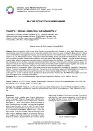
Fig. 7- Examples For The Received Signals<br />
Here few examples of the complete waveform (14 bits) at the<br />
Receiver Output. Values at the right are the comm<strong>and</strong> in hexadecimal.<br />
Red: AGC pulses (ON) Blue: Check bit (flipping) White:<br />
Address (00) Green: Comm<strong>and</strong>.<br />
Algorithm<br />
Automation <strong>using</strong> <strong>8051</strong> <strong>microcontroller</strong> <strong>and</strong> RC5 <strong>remote</strong><br />
Journal of Information Systems <strong>and</strong> Communication<br />
ISSN: 0976-8742 & E-ISSN: 0976-8750, Volume 3, Issue 1, 2012<br />
Conclusion<br />
An automated home can be a very simple grouping of controls, or<br />
it can be heavily automated where any appliance that is plugged<br />
into electrical power is <strong>remote</strong>ly controlled. Costs mainly include<br />
equipment, components, furniture, <strong>and</strong> custom installation.<br />
Ongoing costs include electricity to run the control systems,<br />
maintenance costs for the control <strong>and</strong> networking systems, including<br />
troubleshooting, <strong>and</strong> eventual cost of upgrading as st<strong>and</strong>ards<br />
change. Increased complexity may also increase maintenance<br />
costs for networked devices.<br />
Learning to use a complex system effectively may take significant<br />
time <strong>and</strong> training. Control system security may be difficult <strong>and</strong><br />
costly to maintain, especially if the control system extends beyond<br />
the home, for instance by wireless or by connection to the internet<br />
or other networks.<br />
References<br />
[1] Basics of home <strong>automation</strong>, http://oscarferrer.com.<br />
[2] James gerhart Home <strong>automation</strong> <strong>and</strong> wiring, 28-67.<br />
[3] The RC5 encryption algorithm, http://citeseerx.ist.psu.edu.<br />
[4] IR sensor datasheet, http://pdf1.alldatasheet.com.<br />
[5] Microcontroller AT89C2051 datasheet, http://www.atmel.com.<br />
[6] LCD JHD162A datasheet, http://www.electrokit.se.<br />
[7] Buffer ULN2803 datasheet, http://www.datasheetcatalog.org.<br />
[8] Jivan S. Parab, Vinod G. Shelake Exploring C for <strong>microcontroller</strong>s.<br />
A h<strong>and</strong>s on approach.<br />
<strong>Bioinfo</strong> Publications 277