Piezomechanik
Piezomechanik
Piezomechanik

Create successful ePaper yourself
Turn your PDF publications into a flip-book with our unique Google optimized e-Paper software.
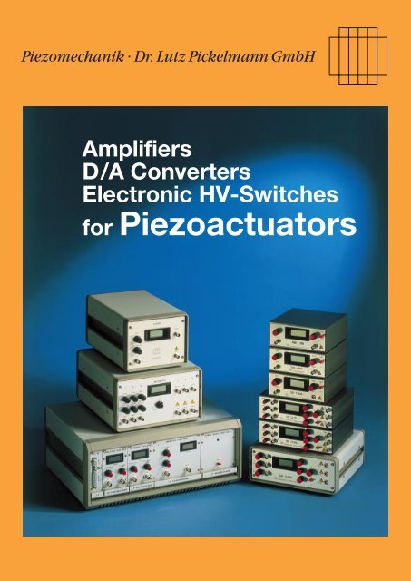
<strong>Piezomechanik</strong> · Dr. Lutz Pickelmann GmbH<br />
Amplifiers<br />
D/A Converters<br />
Electronic HV-Switches<br />
for Piezoactuators
Table of Contents<br />
Introduction . . . . . . . . . . . . . . . . . . . . . . . . . . . . . . . . . . . . . . . . . . . . . . . . . . . . . . . . . . . . . . . . . . . . . . . . . . . . . . . . . 3<br />
Electro-Mechanical relations of piezoelectric actuators . . . . . . . . . . . . . . . . . . . . . . . . . . . . . . . . . . . . . . . . . . . . . . . 4<br />
Practical aspects of dynamically operated piezoactuators . . . . . . . . . . . . . . . . . . . . . . . . . . . . . . . . . . . . . . . . . . . . 7<br />
Selection guide for amplifiers/supply electronics . . . . . . . . . . . . . . . . . . . . . . . . . . . . . . . . . . . . . . . . . . . . . . . . . . . . 9<br />
Special features . . . . . . . . . . . . . . . . . . . . . . . . . . . . . . . . . . . . . . . . . . . . . . . . . . . . . . . . . . . . . . . . . . . . . . . . . . . . 11<br />
Safety instructions . . . . . . . . . . . . . . . . . . . . . . . . . . . . . . . . . . . . . . . . . . . . . . . . . . . . . . . . . . . . . . . . . . . . . . . . . . 11<br />
Useful formulas . . . . . . . . . . . . . . . . . . . . . . . . . . . . . . . . . . . . . . . . . . . . . . . . . . . . . . . . . . . . . . . . . . . . . . . . . . . . . 12<br />
Data of amplifiers<br />
SQV analog amplifiers . . . . . . . . . . . . . . . . . . . . . . . . . . . . . . . . . . . . . . . . . . . . . . . . . . . . . . . . . . . . . . . . . . . . . . . . . 13<br />
Low voltage analog power amplifiers . . . . . . . . . . . . . . . . . . . . . . . . . . . . . . . . . . . . . . . . . . . . . . . . . . . . . . . . . . . . 16<br />
High voltage power amplifiers . . . . . . . . . . . . . . . . . . . . . . . . . . . . . . . . . . . . . . . . . . . . . . . . . . . . . . . . . . . . . . . . . . 19<br />
Bimorph amplifiers . . . . . . . . . . . . . . . . . . . . . . . . . . . . . . . . . . . . . . . . . . . . . . . . . . . . . . . . . . . . . . . . . . . . . . . . . . . 24<br />
D/A Converters, Computer-Interfaces . . . . . . . . . . . . . . . . . . . . . . . . . . . . . . . . . . . . . . . . . . . . . . . . . . . . . . . . . . . . 26<br />
Accessories . . . . . . . . . . . . . . . . . . . . . . . . . . . . . . . . . . . . . . . . . . . . . . . . . . . . . . . . . . . . . . . . . . . . . . . . . . . . . . . . . 28<br />
2 Amplifiers, D/A Converters, Electronic HV-Switches for Piezoactuators http://www.piezomechanik.com
Amplifiers, D/A Converters, Electronic HV-Switches for piezoactuators<br />
1. Introduction<br />
Piezoelectrical actuators are innovative driving systems,<br />
which show increasing application potential for highly sophisticated<br />
driving/positioning tasks in a great variety of technological<br />
fields. The main areas of interest include<br />
• the extreme positioning sensitivity, enabling such<br />
systems to handle dimensions in the atomic scale<br />
• extreme force generation resulting for example in high<br />
acceleration rates during dynamic operation.<br />
For some applications no practicable alternative to piezoactuators<br />
exist<br />
• Piezoelectric actuators are used for the ultraprecise positioning<br />
of components and mechanical setups ranging<br />
from low weight optical elements, up to heavy loads such<br />
as tooling machines. The newest scanning microscope<br />
General considerations for electronic supplies for piezoactuators:<br />
In the simplest case a piezoactuator should move according<br />
to an external signal i.e. from a sinewave generator, or other<br />
source. In most cases, this original signal cannot be applied<br />
directly to the piezoactuator because voltage and power<br />
usually do not match the actuator’s requirements. An amplifier<br />
has to be used to convert the signal to result in sufficient<br />
travel and dynamics of the actuator.<br />
This is an important aspect of actuator’s application:<br />
The adaptation of a piezoelement to a distinct task is determined<br />
only in part by its mechanical properties and geometrical<br />
size. Equally important for the system’s performance<br />
are the properties of the driving electronics.<br />
The same actuator can be used for completely different<br />
operating profiles depending only on the choice of the supply<br />
electronics:<br />
signal<br />
generator<br />
elec. signal<br />
function generator<br />
feedback control electronic<br />
computer<br />
amplifier<br />
pulser<br />
Fig. 1:<br />
Schematic representation of an actuator system<br />
When designing a piezoactuated system the designer<br />
has to deal simultaneously with actuator and supply to<br />
get the optimum matching. A step-by-step definition<br />
whereby the actuator is first-chosen and then a sub-<br />
matching<br />
electronics<br />
technologies such as STMs, AFMs etc. require precise<br />
handling of probe tips with sub-nanometer precision,<br />
which can only done in a reasonable way by using piezomechanical<br />
elements.<br />
• The high acceleration rates/short reaction times predestinate<br />
piezoelements for the control of fast processes in<br />
valve technology, fuel injection application, mechanical<br />
shaking excitation for test purposes with time periods/risetimes<br />
in the microseconds range.<br />
• Piezoactuators are very attractive candidates for active<br />
vibration control and cancellation even in heavy and extended<br />
mechanical structures such as vehicles, airplanes,<br />
helicopters, ships. A special feature is the dual effect of<br />
piezoelectricity, which can be used both for sensing and<br />
actuating. Single element can therefore be used as smart<br />
transducers acting simultaneously as sensor and actuator.<br />
Slow cycling of an actuator requires only a small low power<br />
supply, whereas pulsed operation i.e. generating mechanical<br />
shocks, needs supplies with peakpowers in the kilowatt<br />
range.<br />
Computer control of actuators comprises an additional step:<br />
the computer data has to be converted by a D/A converter of<br />
sufficient speed and resolution, and the low voltage signal is<br />
than amplified to the actuator’s requirements.<br />
piezo<br />
actuator<br />
mechan.<br />
reaction<br />
sequent selection of the supply may lead to costly and<br />
ineffective approaches.<br />
http://www.piezomechanik.com Amplifiers, D/A Converters, Electronic HV-Switches for Piezoactuators<br />
3
2. Electro-Mechanical relations of<br />
piezoelectric actuators<br />
2.1. Principle structures of piezoactuators<br />
Generally, all piezoelectric devices/transducers such as<br />
stacks, bimorphs, tubes can be described as a kind of capacitor<br />
with an electromechanically active dielectric medium:<br />
the PZT ceramic. Therefore, the electrical capacitance of<br />
such devices is an important operating parameter, especially<br />
when adapting the supply electronics for dynamic operation.<br />
The electrical capacitance of piezoactuators is shown in the<br />
data sheet.<br />
The strain within the PZT-medium is related to the internal<br />
electrical field strength when a voltage is applied to the element.<br />
An important consequence for practical consideration<br />
is, that the thinner the PZT-layers are, the lower can be the<br />
driving voltage. Furthermore the degree of lamination determines<br />
the electrical capacitance of piezoactuators.<br />
ceramic endfaces<br />
piezoceramic<br />
layers<br />
electrical<br />
connection<br />
Fig. 2a:<br />
Schematic representation of the capacitive layer structure of a<br />
piezostack<br />
Fig. 2b:<br />
Discretely built-up piezoelectric stack (high voltage type), external<br />
contact electrodes visible<br />
Low voltage actuator types are operated with maximum<br />
voltages ranging from 50 V to 150 V, whereas the high<br />
voltage elements require hundreds of volts up to 1000 V (and<br />
more). For standard stacks the achieved maximum strain is<br />
about 1–1.5‰ of the stack length. There exist highstrain<br />
stacks based on optimized PZT-materials showing a strain of<br />
2‰ and more at fieldstrength of 3 kV/mm.<br />
2.2. Polarity of piezoelectrical elements<br />
For piezoelectrical components an electrical polarity is<br />
usually defined. Piezoelectrical actuators e.g. stacks can only<br />
achieve their maximum response by applying the maximum<br />
voltage with correct polarity. Operation with counterpolarity<br />
voltage although possible is limited to remarkably lower<br />
ratings. A stack actuator shrinks under these conditions,<br />
increasing thereby to some extent the total moving range of<br />
the stack (see brochure “piezomechanical stackactuators”).<br />
Bare piezostacks without casing are usually electrically insulated<br />
at the mechanical mounting points. They are supplied<br />
with pigtails showing the polarity by red(+) and black(–) insulation.<br />
Such elements can be combined therefore with positive<br />
or negative voltage supplies without difficulty. The situation<br />
changes, when actuators with casing are used. Here, the<br />
ground is defined by the coax-cable and therefore the polarity<br />
of the supply voltage is fixed.<br />
Piezoactuators with casing and the supply electronics from<br />
PIEZOMECHANIK are designed for positive polarity both for<br />
low voltage and high voltage actuators. This supports the<br />
easy combination of higher voltage actuators with lower<br />
voltage supplies, which is an important aspect for dynamic<br />
operation of actuators (see section 2.5.).<br />
2.3. Operating characteristics of piezoactuators<br />
The expansion of piezoelectric actuators is illustrated by<br />
voltage/expansion diagrams showing the well-known<br />
hysteresis (fig.3).<br />
rel.<br />
expansion<br />
rel. voltage<br />
Fig. 3:<br />
Relative voltage/expansion diagram of a free running piezoactuator for<br />
different voltage reversal points<br />
4 Amplifiers, D/A Converters, Electronic HV-Switches for Piezoactuators http://www.piezomechanik.com
Actuators are normally classified by the maximum applicable<br />
voltage for maximum stroke, and characterised as low<br />
voltage and high voltage types. For newcomers in piezotechnology,<br />
this sometimes gives the impression, that the voltage<br />
rating of an actuator is the sole criterion for selecting a<br />
proper electronic supply. This is however not correct.<br />
For any application of piezoactuators the electrical power/<br />
current balance for charging and discharging the piezoactuator’s<br />
capacitance has to be kept in mind. The variety of<br />
electrical supplies on offer is due mainly to the different<br />
power/current ratings of these devices.<br />
The charge/current balance during operation is related to<br />
the capacitive nature of actuators as shown below:<br />
Basic capacitor equation<br />
Q(t) = C U(t) C actuator’s capacitance<br />
Q actual electrical charge<br />
U applied voltage<br />
Obviously the expansion of an actuator is also related to<br />
the quantity Q of electrical charge stored in the actuator’s<br />
capacitance C, when a voltage U is applied.<br />
From this charge balance, the kinetic parameters of motion<br />
like speed and acceleration can be derived. These relations<br />
are the base for specifying the necessary current/power for<br />
distinct driving conditions.<br />
Actuator’s position l ~ charge = Q(t)<br />
.<br />
Speed v ~ current I = dQ/dt = Q(t)<br />
..<br />
Acceleration b ~ variation of current = dI/dt = Q(t)<br />
The generation for example of a sine-wave oscillation by<br />
a piezoactuator requires a defined supply current depending<br />
on actuator’s capacitance and moving amplitude.<br />
Therefore an amplifier has to be selected for both criteria:<br />
voltage and current.<br />
Another consequence of the above is that, during a<br />
steady state of the actuator (constant position, constant<br />
force) no current is flowing, therefore no power is required.<br />
When a charged actuator is disconnected from<br />
the supply, it holds its position. This is an important<br />
difference to electromagnetic systems, where a constant<br />
position requires constant electrical power due to the<br />
sustaining current.<br />
The speed of an actuator cannot be increased infinitely even<br />
by very high currents, but is limited by the elastic properties<br />
of the stack. The maximum speed of stacked elements is in<br />
the range of a few m/sec.<br />
Because of the very limited moving range of piezoactuators<br />
the generation of above speeds requires high acceleration<br />
rates up to 10 4 –10 5 g.<br />
During operation of a piezodriven mechanical setup for highly<br />
dynamic application, it has to be verified that the mechanics<br />
coupled to the actuator shows a sufficiently high stiffness/<br />
resonant frequency, otherwise the mechanics cannot follow<br />
actuator’s motion and it is fruitless to optimize the drive for<br />
high speed/acceleration.<br />
2.4. Peak current, average current<br />
Piezoactuators require electrical power/current only during<br />
dynamic operation. Expansion and contraction are characterized<br />
by charging/discharging currents.<br />
The short term available maximum peak current of a supply<br />
determines the minimum risetime/maximum speed of an<br />
actuator. Amplifiers of the series LE provide a special booster<br />
stage for high peak currents to get minimum risetimes.<br />
The average current of a supply determines the longterm<br />
cw-repetition rate of charging/discharging an actuator.<br />
For cw sine oscillation of an actuator, the required peak and<br />
average currents show a fixed ratio of approx. 3:1. Therefore,<br />
the selection of a supply to obtain a distinct cw-actuator frequency<br />
has to consider both, peak and average current data.<br />
2.5. Power efficiency<br />
This section will lead on the first glance to the (surprising)<br />
result, that it is sometimes very reasonable and necessary to<br />
combine a high voltage actuator with a low voltage supply,<br />
where only a fraction of the actuator’s maximum amplitude<br />
can be achieved.<br />
The reason for this strategy are twofold:<br />
• optimizing power efficiency of a dynamically operated<br />
actuator system<br />
• minimizing selfheating of a dynamically operated actuator.<br />
The basic idea is easily demonstrated with the following<br />
example, where the task requires the generation e.g. of a<br />
+/–2,5 µm sine oscillation with a distinct frequency:<br />
The first example uses an actuator type PSt 500/5/5, where<br />
500 V has to be applied to get the full stroke of 5 µm.<br />
A second example is to use the longer stack PSt 500/5/15<br />
capable for a 15 µm motion at 500 V, showing an actuator’s<br />
capacitance 3 times larger than in the 1st case.<br />
The important fact is, that with the longer stack only 150 V<br />
are needed to get the desired 5 µm stroke.<br />
Comparing the actuators’ energy content 1/2 CU 2 respectively,<br />
despite its larger capacitance the longer stack is<br />
favoured regarding power efficiency as only 1/3 of the power<br />
necessary to drive the shorter PSt 500/5/5 with full strain is<br />
required. It is obvious, that a 150 V system’s total power efficiency<br />
is further improved by using a 150 V supply showing<br />
higher current output compared to a 500 V supply operated<br />
at reduced voltage rating.<br />
In the above described strategy, the problem of selfwarming<br />
under dynamic operating conditions is minimized by the<br />
reduced power input and by distribution of the dissipated<br />
energy over a larger volume/surface of the longer actuator.<br />
This is a powerful method to extend the application range of<br />
piezoactuators to high frequency cw-operation without the<br />
risk of overheating.<br />
This strategy of dynamic operation of actuators with reduced<br />
strain shows restrictions in other operating parameters: A<br />
longer stack has a lower stiffness and resonance, and it has<br />
to be determined, whether this is acceptable for a distinct<br />
application.<br />
Finally, an important contribution to the overall power<br />
efficiency of an actuator system is the use of recharger<br />
amplifiers (switched amplifiers).<br />
In most applications, piezoactuators display mainly a reactive<br />
load, where the energy content of a charged actuator flows<br />
back to the amplifier during the discharging cycle. Switched<br />
amplifiers RCV are able to recycle this energy with high efficiency,<br />
so that the needed linepower for a dynamically operated<br />
system has only to cover the (much smaller) active part<br />
of the power balance.<br />
This active power is drawn from the system as mechanical<br />
power or dissipated by the selfheating of the actuators.<br />
This technique shows the optimum of systems’s overall<br />
power efficiency, and favours actuator applications, where<br />
high power levels are required e.g. for active vibration cancellation<br />
in heavy mechanical structures (vehicles, airplanes<br />
etc.) or anywhere, where the power consumption from the<br />
power supply is restricted i.e. battery operated systems.<br />
Power efficiency � is defined as<br />
� = (P r–P al) Pr = reactive power output from amplifier<br />
� = (P r) Pal = active power consumption from line<br />
An ideal amplifier without internal losses shows an efficiency<br />
1.<br />
http://www.piezomechanik.com Amplifiers, D/A Converters, Electronic HV-Switches for Piezoactuators<br />
5
2.6. Frequency response<br />
The performance of an amplifier is characterized by its frequency<br />
response, describing what cw-frequency/amplitude<br />
relations that can be achieved for a defined capacitive load.<br />
The achievable maximum frequencies of an actuator/supplysystem<br />
depend both on the output power of the supply, the<br />
capacitance of the driven actuator and the oscillation amplitude.<br />
To make the selection of an amplifier/actuator combination<br />
with respect to frequency response easier, some response<br />
curves for different capacitive loads are shown in the<br />
data sheet for distinct amplitudes. The response for intermediate<br />
capacitances are achieved by simple interpolation.<br />
An additional figure for an amplifier’s performance is the<br />
achievable minimum risetime, which is tabulated for some<br />
load capacitances (see section 2.4.).<br />
2.7. Voltage stability, noise<br />
One of the most striking features of piezoactuators is their<br />
unlimited positioning sensitivity, which explains the sub-nanometer<br />
resolution for example scanning tunnel microscopes:<br />
A infinitely small voltage step Æ U is transformed into infinitely<br />
small mechanical shift Æ l.<br />
Æ l = l Æ U/U l = actuator’s shift for signal voltage U<br />
Neglecting external influences, the positioning sensitivity of<br />
an actuating system is limited only by the stability of the<br />
electronic supply (noise).<br />
Example:<br />
The amplifiers SQV 150 show a noise of approx. 1 mV equivalent<br />
to a S/N ratio of about 10 5 . A 100 µm actuator such as<br />
the PSt 150/7/100 VS 12 operated with the SQV 150 shows a<br />
variation in position of only 1 nm.<br />
2.8. Pulsed operation of piezoactuators<br />
An important feature of piezoactuators is their capability to<br />
produce extreme forces and acceleration rates, which can be<br />
used for fast switching of valves or to produce mechanical<br />
shocks. In such cases, the actuator should switch in as short<br />
time as possible between 2 distinct levels, whereas the exact<br />
motion profile between these levels is not important.<br />
The minimum risetime of an actuator can derived from its<br />
elastic properties:<br />
A short electrical pulse excites the resonant oscillation of the<br />
actuator and the minimum risetime Tp can be estimated by<br />
Tp Å Tr/3 Tr = period time of actuator’s resonance<br />
Tp = minimum risetime in pulsed operation<br />
Example:<br />
A systems’s resonant frequency of 3 kHz results in a minimum<br />
mechanical risetime of about 100 µsec.<br />
A simple calculation shows, that above shown pulse generation<br />
requires peak powers up to the kilowatts range with currents<br />
of 10 to 100 Amperes. In these cases it is reasonable<br />
not to use analogue amplifiers but electronic pulse switches.<br />
The common design of a HV-pulse generator consists of a<br />
high voltage supply, which continuously charges at a defined<br />
low power (i.e. 50 Watt) a large internal charge storing<br />
capacitor.<br />
This capacitor delivers short term the very high currents to<br />
the external piezoactuator capacitance, when it is switched<br />
by transistors via a load resistor R. The load resistor R acts<br />
as current limiter to avoid electrical overpowering and<br />
defines the time constant RC of the pulser (rise/fall-time)<br />
according the well-known relation<br />
Ua = U o (1-e -t/RC )<br />
R = internal load resistor of switch<br />
C = capacitance of external load (piezoactuator)<br />
Ua = voltage level at actuator<br />
Uo = supply voltage from internal charge storing capacitor<br />
For the operation of the HVP’s 3 time constants have to be<br />
distinguished:<br />
• Switching time of output transistors:<br />
order of magnitude: 1 µsec<br />
defines the minimum electrical pulsewidth<br />
• Time constant RC:<br />
Defines the signal/voltage risetime at the actuator.<br />
Pulsewidths shorter RC lead to a partial charging of the<br />
actuator and thereby to intermediate positions between<br />
“low” and “high”<br />
• Period time of actuator/actuated system (fig. 4.):<br />
This time constant defines the minimum mechanical<br />
rise/fall-time of the system.<br />
To excite the minimum mechanical risetime Tp of an actuator,<br />
the RC time constants of the pulsersystem has to be<br />
shorter than Tp.<br />
voltage step<br />
Fig. 4:<br />
Excitation of a mechanical pulse by a voltage step 0V/Uo; lo final static<br />
position of actuator<br />
2.9. Feedback controlled systems<br />
Piezoelectric actuators are well-suited for setting up electronically<br />
controlled systems for fast and precise handling of<br />
mechanical parameters such as position, speed and force.<br />
Because of the hysteretic and slightly nonlinear behaviour of<br />
piezoactuators, and nonpredictable external influences, this<br />
has to be done by feedback control. A sufficiently fast and<br />
sensitive transducer picks up the actual position or other<br />
parameter of interest and the signal is evaluated by feedback<br />
control electronics, producing the control signal for the<br />
actuator.<br />
The overall efficiency e.g. precision of such a system is<br />
determined by the transducer and electronics and not by the<br />
actuator. The high performance of feedback controlled<br />
systems is demonstrated by the atomic resolution of the<br />
scanning tunnel microscopes (STMs).<br />
6 Amplifiers, D/A Converters, Electronic HV-Switches for Piezoactuators http://www.piezomechanik.com
A further application is the active stabilization of mechanical<br />
arrangements e.g. laser resonators against misalignment due<br />
to thermal drifts or mechanical shocks (see “feedback controlled<br />
stabilization PiStab 2”).<br />
3. Practical aspects of dynamically operated<br />
piezoactuators<br />
3.1. Preloading, reset mechanisms<br />
Piezoceramic is sensitive to tensile stress, it shows a damage<br />
strain of only 1‰.<br />
Note, that this tensile stress can be created externally and<br />
also internally by dynamic operation. This fact is easily seen<br />
in Fig 4/sec. 2.8., where the application of an electric pulse<br />
leads to overshooting of the actuator relative to the steady<br />
state position. This overshooting can cause tensile stress<br />
and thereby damage to the actuator when the relevant forces<br />
are not compensated by other means.<br />
To prevent damage by tensile forces the following strategies<br />
are commonly applied:<br />
• passive preloading/reset of actuators<br />
This technique is mostly applied to stack actuators:<br />
An elastic spring compresses the piezostack with a defined<br />
force shown in fig. 5a, b. A preloaded stack is less sensitive<br />
to externally applied tensile stress for several reasons, i.e. a<br />
reduction in stacklength is achieved by the preload force. A<br />
Fig. 5a:<br />
Mirror tilter with passive prestress/reset<br />
Fig. 5b:<br />
Linear stackactuator with passive prestress/reset<br />
http://www.piezomechanik.com Amplifiers, D/A Converters, Electronic HV-Switches for Piezoactuators<br />
piezostack<br />
tilting<br />
prestress spring<br />
piezostack<br />
mirror surface<br />
prestress/reset<br />
spring<br />
7
eal tensile stress is acting on the ceramic only, when the<br />
external force lengthens the stack beyond the original (loadfree)<br />
state.<br />
Furthermore, the elastic counterforce slows down the moving<br />
mass in the overshoot phase during dynamic operation.<br />
So, the applied preload force can be chosen according the<br />
tilting<br />
Fig. 6a:<br />
Mirror tilter with active (push-pull) reset<br />
piezostack piezostack<br />
Fig. 6b:<br />
Linear push-pull arrangement of piezostacks for active reset<br />
simple mass acceleration law to accommodate the accelerated<br />
masses within the desired short rise/fall-times.<br />
The standard preloading VS of PIEZOMECHANIK actuators<br />
cover a wide range of applications. It is possible to apply<br />
higher preload forces, which can be supplied on request or<br />
can be applied externally (see brochure “piezomechanical<br />
stackactuators”).<br />
• active reset<br />
(push-pull mode, antagonistic configuration)<br />
mirror surface<br />
A more sophisticated reset mechanism for compensating<br />
dynamic forces is the arrangement with two complementary<br />
working actuators shown in fig. 6a, b. The advantages<br />
include a symmetric force balance for both directions of<br />
motion, and higher resonance frequencies compared with<br />
passive preloading.<br />
3.2. Selfheating<br />
Another aspect of dynamically operating piezoactuators is<br />
their selfheating. Due to the ferroelectric nature of PZT ceramics,<br />
the electrical operating power transferred to the actuator<br />
is partially dissipated as heat. For example an actuator<br />
PSt 150/5/15 with full amplitude operation heats up to the<br />
operating temperature limit at about 600 Hz. Higher temperatures<br />
will shorten an actuators lifetime. A further increase of<br />
frequency therefore requires cooling or an equivalent reduction<br />
of amplitude (see sec. 2.5).<br />
Simple surface cooling results in limited success for large<br />
volume actuators, because PZT ceramics have poor thermal<br />
conductivity. Furthermore measuring the actuator’s temperature<br />
on its surface does not reflect the internal conditions. A<br />
good parameter for checking the volume temperature is the<br />
temperature dependence of the electrical capacitance of the<br />
actuator leading to a shift of the current balance.<br />
Fig. 7:<br />
Temperature dependence of the electrical capacitance of a typical<br />
piezoactuator (relative to capacitance at roomtemperature)<br />
8 Amplifiers, D/A Converters, Electronic HV-Switches for Piezoactuators http://www.piezomechanik.com
3.3. Vibration control, acoustical noise<br />
Every dynamic excitation of a piezoactuator attached to a<br />
mechanical structure acts back on this structure. Pulsed or<br />
oscillating actuators generate vibrations in the mechanical<br />
structure. In case of a resonance a large amplitude response<br />
can emerge even for small excitation levels, which can interfere<br />
with the regular function of the structure. Therefore,<br />
dynamically operated structure have to be designed for sufficiently<br />
large resonant frequencies, and include sufficient<br />
damping to avoid these unwanted side effects at the driving<br />
frequency.<br />
Vibration suppression can be done in passive or active ways.<br />
An example for active pulse compensation is shown in fig. 8,<br />
where a counteracting piezostack compensates for the<br />
repulse of the original stack, e.g. shifting a mirror.<br />
Generally, piezoelements are powerful tools for vibration<br />
control, both for generating vibrations (shakers) and for cancellation<br />
(active vibration isolation and damping). Active com-<br />
static suspension<br />
mirror compensating<br />
mass<br />
piezostack piezostack<br />
impulse 0<br />
Fig. 8:<br />
Mechanical impulse compensation<br />
pensation can be done in feedback controlled systems,<br />
where a transducer detects an incoming vibration, and<br />
excites an antivibration with proper amplitude and phase<br />
relation via an actuator.<br />
From ergonomic aspects, it must be kept in mind, that<br />
actuator vibrations can produce acoustical noise which may<br />
be very uncomfortable for the operator.<br />
4. Selection guide for amplifiers/supply electronics<br />
PIEZOMECHANIK offers a wide range of supply electronics<br />
to obtain the optimum solution for different applications<br />
of piezoactuated systems.<br />
For specifying dynamically operated actuator/amplifier<br />
systems the power/current requirements are determined<br />
by the actuator’s capacitance. Note that the actuator’s<br />
capacitance can vary up to 50% (e.g. see section 3.2.)<br />
leading to correspondingly elevated power/current<br />
ratings.<br />
The supply electronics and actuators from PIEZO-<br />
MECHANIK are set to positive polarity for both high<br />
voltage and low voltage components, so that widest<br />
compatibility is achieved e.g. for power efficient<br />
arrangements according sec. 2.5.<br />
On request PIEZOMECHANIK supplies piezocomponents<br />
for negative operating polarity.<br />
4.1. SQV amplifiers<br />
The range of SQV amplifiers comprises the 3 main voltage<br />
ranges, where piezoactuators are offered namely 150 V<br />
(+200 V), 500 V and 1000 V. The output power is a few watts,<br />
which is sufficient for most applications. Smaller volume<br />
actuators can be operated even with higher dynamic/frequencies.<br />
SQV amplifiers show low noise and are therefore<br />
best suited for positioning tasks with highest positioning sensitivity.<br />
SQV amplifiers are available as 3-channel versions e.g. for<br />
optomechanical xyz adjusters.<br />
4.2. LE amplifiers<br />
LE amplifiers are used, when the power/current requirements<br />
cannot be covered by the SQV amplifiers. The LE series<br />
includes current boosters for optimum system power efficiency,<br />
when e.g. a high frequency sinoidal oscillation has to<br />
be excited, or to get short rise/fall-times for a rectangular<br />
signal.<br />
The LE amplifiers are available for power levels up to hundreds<br />
of watts.<br />
Due to these elevated power levels, selfheating of actuators<br />
according sec. 3.2. should be considered.<br />
4.3. RCV recharging amplifiers<br />
The RCV switched amplifiers are designed for driving<br />
large volume/large capacitance piezoactuators with high<br />
currents and powers up to the kilowatt range beyond the<br />
levels of the LE analog amplifiers. This situation occurs for<br />
example with the active excitation and cancellation of<br />
vibrations in heavy mechanical structures e.g. vehicles,<br />
airplanes etc.<br />
Because the design of RCV amplifiers has to be adapted to<br />
some extent to the operated load, there are no standardized<br />
devices. In principle, RCV amplifiers can also be designed for<br />
lower power ratings. Please contact us for details.<br />
4.4. Bipolar amplifiers<br />
Usually piezoactuators such as stacks are operated unipolar<br />
or asymmetrically bipolar to get maximum displacement.<br />
Some applications exist, where piezoelements are operated<br />
symmetrically bipolar, but to avoid depolarization of the PZT<br />
ceramic, the electrical field strength and thereby actuator’s<br />
efficiency has to be held sufficiently low.<br />
Reasons for bipolar operation include simple electrical driving<br />
conditions e.g. of piezobenders (bimorphs), shearmode<br />
actuators or enhancement of stack actuators lifetime e.g.<br />
within feedback control loops for position stabilization. In this<br />
case, the middle position is defined by 0 V, no offset is required<br />
for symmetric positioning range. This leads to long-<br />
http://www.piezomechanik.com Amplifiers, D/A Converters, Electronic HV-Switches for Piezoactuators<br />
9
term low electrical fields preventing materials degradation by<br />
charge carrier diffusion.<br />
Nevertheless, bipolar amplifiers can also generate unipolar or<br />
asymmetric output by applying a proper signal.<br />
4.5. BMT, AGV antagonistic amplifiers<br />
The AGV/BMT amplifiers are designed to drive push-pull<br />
(antagonistic) stack arrangements or piezobenders (“Bimorphs”)<br />
described in section 3.1. By electrical preloading,<br />
the full operating range of the ceramics can be used without<br />
the risk of depolarization which may happen during simple<br />
bipolar operation. The modulation of the antagonistic piezoelements<br />
is done by a single driving signal, complementary<br />
action is achieved by different static offsets shown in fig. 9a,<br />
b, c. This strategy ensures forced synchronization of motion<br />
of the 2 elements even under high dynamic driving conditions.<br />
For an antagonistic setup, the actuators have to show potential<br />
free design, meaning that the operating ground of the<br />
AGV/BMT<br />
Fig. 9a: Push-pull-stack arrangement with schematic electronic supply<br />
configuration<br />
Fig. 9b:<br />
Operation of a parallel-bimorph with electrical preloading<br />
AGV/BMT amplifier<br />
Fig. 9c:<br />
Equivalent circuit to piezoactuator arrangements 9a, 9b<br />
AGV/BMT<br />
amplifier<br />
piezoelements has to be separated from general ground of<br />
the arrangement.<br />
4.6. HVP high voltage switches for pulse operation<br />
HV-pulse generators are used when currents beyond the<br />
level of common amplifiers are necessary and where a<br />
steady movement of an actuator is not required, but only<br />
defined levels should be set within short times or where<br />
mechanical shocks have to be produced.<br />
The HVP high voltage pulse generators from PIEZOMECHA-<br />
NIK show some interesting features enabling the user to<br />
drive piezoactuators in a more sophisticated way than the<br />
simple “high”, “low” procedure with common switches.<br />
Beside the levels “charging = high”, “discharging = low”<br />
there exist a third level “neutral”, where the output is set to<br />
high resistance, so that the charge content (= position) of the<br />
actuator is kept constant. Thus the system can be set and<br />
held in intermediate positions. This is achieved by applying<br />
signal pulses with width less the time constant RC of the<br />
system, leading to only a partial charging of the actuator’s<br />
capacitance corresponding an intermediate position.<br />
A general approach for pulsed actuator operation is not to<br />
oversize current specs for a distinct application, because too<br />
powerful pulses may cause unnecessary mechanical and<br />
electrical stress to the system. On the other hand the<br />
mechanical reaction time cannot be infinitely improved by<br />
increasing the pulsepower (see sec. 2.8.).<br />
4.7. Computer interfaces<br />
For computer control of piezoactuators a lot of designs and<br />
arrangements for interfacing exist. The selection of the<br />
proper interface for a distinct application depends on the<br />
basic hardware/software the user can provide, and the<br />
flexibility he wants to achieve with his setup.<br />
• Computer with internal D/A converter: computer output is<br />
an analog signal<br />
The supplies low voltage analog signal output (e.g. 0 V to<br />
+10 V) is applied directly to the analog amplifiers etc. from<br />
PIEZOMECHANIK.<br />
• HV-PC-card: The computer output is an analog signal. This<br />
card is inserted in the computer and produces immediately<br />
an analog-HV-signal for voltages up to +150 V or +500 V<br />
also in multichannel configuration. The power range is<br />
similar to the SQV or lower power LE amplifiers. This signal<br />
is directly applicable to the piezoactuator. Space saving<br />
configuration.<br />
• External D/A Converters: The computer output is digital<br />
data.<br />
In this case, the digital data has to be transferred via a<br />
serial or parallel interface similar to any other peripheric<br />
device for a computer e.g. a printer.<br />
The data is then converted by a D/A stage into an analog<br />
signal with subsequent amplification by usual analog<br />
amplifiers.<br />
The low voltage D/A converting unit can be a stand-alone<br />
device, or can be integrated to the amplifiers cabinet. In all<br />
these cases, the analog functions of the amplifiers remain<br />
active e.g. a manual setting of an “offset” voltage is possible,<br />
which is useful for adjusting setups before starting<br />
computer control. Multichannel systems are available.<br />
10 Amplifiers, D/A Converters, Electronic HV-Switches for Piezoactuators http://www.piezomechanik.com
5. Special features<br />
Analog amplifiers from PIEZOMECHANIK show some special<br />
features, which are very useful for the operation of piezoactuators:<br />
“Offset”<br />
The amplifiers are provided with a potentiometer where a<br />
DC-output voltage can be manually set over the full operating<br />
range. In this mode, the amplifier can be used as an<br />
adjustable voltage supply without the application of an<br />
external signal.<br />
When an external signal is amplified, the “Offset” voltage is<br />
superimposed automatically. This is useful, when the signal<br />
generator produces only bipolar signals which have to be<br />
shifted to get the unipolar signal required to drive piezoelements<br />
effectively.<br />
“Amplitude”<br />
Using this potentiometer, the input signal can be adapted to<br />
the working range of the amplifier. It is possible to use signal<br />
levels 5 V as well as 10 V (e.g. from standard D/A converting<br />
units).<br />
Current booster<br />
Higher power amplifiers such as the LE types are provided<br />
with a current booster, which enable the amplifier to produce<br />
a much higher current (for a limited time) than the long term<br />
average current. In this mode, the amplifier is optimized for<br />
high power efficiency when a capacitive load such as a<br />
piezoactuator is operated.<br />
The current booster reduces further the risetime, when<br />
rectangular signals are applied.<br />
For these amplifiers the risetimes for a variety of loads are<br />
tabulated in the datasheet.<br />
Monitor output<br />
The average output voltage is shown on the front display of<br />
the amplifiers.<br />
Realtime signal monitoring is done by the “Monitor”-output,<br />
which represents the actual power output status by a 1:100<br />
ratio low power signal. The monitor-output is used for realtime<br />
representation via an oscilloscope. Further it can be<br />
used as a signal source for any control arrangement (feedback<br />
control, voltage limitation), where information about the<br />
current status of the actuator is needed.<br />
6. Safety Instructions<br />
• During operation of piezoactuators voltages and electrical<br />
currents are present which may be harmful to the<br />
operator<br />
• Installation and operation of actuators and electronics<br />
supplies must be carried out by authorized personal<br />
only<br />
• All electrical installation of electric supplies, cables and<br />
connectors must be carried out according to standard<br />
safety regulations<br />
• Piezoactuators can show large electrical capacitances,<br />
and charged actuators can store electrical charge at<br />
high voltage levels, even for long times after being disconnected<br />
from the power supply.<br />
When large volume actuators are not in use, discharge<br />
them carefully, and hold them shortcircuited.<br />
• Piezoactuators can generate electrical charge at high<br />
voltage levels, when varying load or temperature is<br />
acting on actuators with open leads.<br />
When large volume actuators are not in use, discharge<br />
them carefully, and hold them shortcircuited.<br />
• Take care when opening amplifiers and pulsegenerators.<br />
High voltage levels can be held for a long time<br />
after disconnecting the devices from line due to large<br />
capacitance internal capacitors. If these devices must<br />
be opened, wait at least 15 minutes after disconnecting<br />
them from line. Complete discharge of the internal<br />
capacitors has to be ensured by shortcircuiting via a<br />
proper resistor.<br />
http://www.piezomechanik.com Amplifiers, D/A Converters, Electronic HV-Switches for Piezoactuators 11
7. Useful formulas<br />
Notice: the following relations are dealing with ideal capacitors, where the capacitance is invariable under the driving conditions.<br />
But piezoactuators show to some extent deviations from this ideal behaviour due to their ferroelectric nature. Their<br />
capacitances depend on electrical fieldstrength (voltage level), temperature and other parameters and may exceed the nominal<br />
values by 50%, which are stated in the data sheet.<br />
General:<br />
capacitor relation C = Q/U<br />
charging/discharging current<br />
I(t) = C dU/dt<br />
Average current l, t repetition rate, U o maximum voltage<br />
Sinuoidal excitation<br />
Unipolar signal<br />
Current<br />
U o max. supply voltage<br />
f frequency<br />
C actuators capacitance<br />
Peak current<br />
Average current<br />
I a = U oC/t<br />
U(t) = U o/2 (1-cos 2 p ft)<br />
I(t) = U o C p f sin (2 p ft)<br />
I p = p U max C f<br />
I a = U max C f<br />
Peak current exceeds average current by factor p.<br />
Current booster needed for optimum power efficiency.<br />
Symmetric triangular signal<br />
Peak current<br />
Average current<br />
I p = U maxCf<br />
I a = U maxCf<br />
No current booster necessary.<br />
Pulse excitation<br />
Operating voltage Ua(t) of actuator:<br />
Charging current Ic(t)<br />
Ua(t) = U o (1-e –t/RC )<br />
Ic(t) = (U o-Ua(t))/R<br />
R load resistor of pulse generator (see sec.2.8.)<br />
Peak current at pulse onset:<br />
Average current<br />
Ic max = U o/R<br />
I a = U oCw<br />
w repetition rate, U o supply voltage<br />
Power balance<br />
Energy content E of a charged capacitance<br />
E = 1/2 CU o 2<br />
Average power consumption P A during cycling with repetition<br />
rate w<br />
P A = 1/2 CU o 2 w<br />
Dissipated power (selfheating problem)<br />
During the charging/discharging cycles, the transferred<br />
power is partially dissipated into heat according<br />
P dis = tand CU o 2 w<br />
tand dissipation factor<br />
5–10% of total power with common PZT actuator ceramics<br />
12 Amplifiers, D/A Converters, Electronic HV-Switches for Piezoactuators http://www.piezomechanik.com
SQV analog amplifiers (low voltage/high voltage types)<br />
SQV 1/150 single channel amplifier<br />
+150 V output<br />
Special features: see chapter 5.<br />
Potentiometer “Offset”<br />
Potentiometer “Amplitude”<br />
Input<br />
Input: +/–5 V (+/–10 V see chapter 5)<br />
Input resistance: 10 kOhm<br />
Input connector: BNC<br />
Output:<br />
Voltage range: –10 V thru +150 V<br />
Max. peak current/average current: approx. 60 mA<br />
Gain: 30<br />
Noise: approx. 1 mVpp with capacitive load (actuator)<br />
Connector: BNC<br />
Display: LCD, 3 digits<br />
Dimensions: WxDxH 165x210x70 mm<br />
Weight: approx. 1.7 kg<br />
SQV 3/150 triple channel device<br />
3 independent channels<br />
Performance data /channel equiv. SQV 1/150<br />
LC-voltage display, channel selection by dial<br />
Dimensions: WxDxH 215x210x70<br />
Weight: 2.4 kg<br />
Option:<br />
Amplifier for 200 V output: on request<br />
open<br />
output:<br />
U max/2 >20 kHz<br />
Frequency response<br />
Risetimes:<br />
(for square wave input signal)<br />
Load risetime<br />
capacitance to 100 V/150 V<br />
22 µF 40 msec /80 msec<br />
4.2 µF 8 msec /18 msec<br />
1.2 µF 2 msec / 5 msec<br />
330 nF 0.5 msec /1.2 msec<br />
http://www.piezomechanik.com Amplifiers, D/A Converters, Electronic HV-Switches for Piezoactuators 13
SQV 1/500 single channel amplifier<br />
+500 V output<br />
Special features: see chapter 5.<br />
Potentiometer “Offset”<br />
Potentiometer “Amplitude”<br />
Input<br />
Input: +/–5 V (+/–10 V see chapter 5)<br />
Input resistance: 10 kOhm<br />
Input connector: BNC<br />
Output:<br />
Voltage range: 0 V thru +500 V<br />
Max. peak current/average current: approx. 20 mA<br />
Gain: 100<br />
Noise: approx. 1 mVpp with capacitive load (actuator)<br />
Connector: BNC<br />
Display: LCD, 3 digits<br />
Dimensions: WxDxH 165x210x70 mm<br />
Weight: approx. 1.7 kg<br />
SQV 3/500 triple channel device<br />
3 independent channels<br />
Performance data /channel equiv. SQV 1/500<br />
LC-voltage display, channel selection by dial<br />
Dimensions: WxDxH 215x210x70<br />
Weight: 2.4 kg<br />
open<br />
output:<br />
U max/2 >20 kHz<br />
Frequency response<br />
Risetimes:<br />
(for square wave input signal)<br />
Load risetime<br />
capacitance to 300 V/500 V<br />
1.2 µF 20 msec / 42 msec<br />
660 nF 10 msec / 22 msec<br />
330 nF 5 msec / 11 msec<br />
100 nF 1.5 msec / 3.5 msec<br />
30 nF 0.5 msec / 1.2 msec<br />
14 Amplifiers, D/A Converters, Electronic HV-Switches for Piezoactuators http://www.piezomechanik.com
SQV 1/1000 single channel amplifier<br />
+1000 V output<br />
Special features: see chapter 5.<br />
Potentiometer “Offset”<br />
Potentiometer “Amplitude”<br />
Input<br />
Input: +/–5 V (+/–10 V see chapter 5)<br />
Input resistance: 10 kOhm<br />
Input connector: BNC<br />
Output:<br />
Voltage range: 0 V thru +1000 V<br />
Max. peak current/average current: approx. 10 mA<br />
Gain: 200<br />
Connector: LEMOSA OS.250 (BNC adaptor available)<br />
Noise: approx. 5 mVpp with capacitive load (actuator)<br />
Display: LCD, 3 digits<br />
Dimensions: WxDxH 165x210x70 mm<br />
Weight: approx. 1.7 kg<br />
SQV 3/1000 triple channel device<br />
3 independent channels<br />
Performance data /channel equiv. SQV 1/1000<br />
LC-voltage display, channel selection by dial<br />
Dimensions: WxDxH 255x290x115<br />
Weight: 3.5 kg<br />
open output<br />
U max/2 >20 kHz<br />
Frequency response<br />
Risetimes:<br />
(for square wave input signal)<br />
Load risetime<br />
capacitance to 700 V/1000 V<br />
1.2 µF 70 msec /140 msec<br />
330 nF 20 msec /35 msec<br />
100 nF 6 msec /10 msec<br />
30 nF 1.8 msec / 3 msec<br />
http://www.piezomechanik.com Amplifiers, D/A Converters, Electronic HV-Switches for Piezoactuators 15
Low voltage analog power amplifiers<br />
LE 150/025 single channel amplifier<br />
+150 V output<br />
Special features: see chapter 5.<br />
Potentiometer “Offset”, “Amplitude”, Current Booster,<br />
Monitor output<br />
Input<br />
Input: +/–5 V (+/–10 V see chapter 5)<br />
Input resistance: 10 kOhm<br />
Input connector: BNC<br />
Output:<br />
Voltage range: –10 V thru +150 V<br />
Max. peak current: approx. 250 mA<br />
Max. average current: approx. 70 mA<br />
Gain: 30<br />
Noise: approx. 15 mVpp<br />
Connector: BNC<br />
Display: LCD, 3 digits<br />
Dimensions: WxDxH 185x330x150 mm<br />
Weight: approx. 4 kg<br />
Options:<br />
Multichannel arrangements: on request<br />
Amplifier for 200 V output: on request<br />
Computer interfaces:<br />
Optionally, the amplifier LE 150/025 can be equipped by a serial or parallel (CENTRONIX) computer interface (designation as<br />
LE 150/025-S or/-P respectively) for digital control by a fast data transfer and D/A conversion. Up to 3 channels can be operated<br />
simultaneously.<br />
All analog functions of the amplifier remain active. By using ”offset” the amplified signal can be superimposed by a DC-voltage<br />
and the operating voltage range can be varied by ”amplitude” for easy adaption to a distinct application. The resolution is<br />
12 bit.<br />
Order code<br />
LE 150/025 analog amplifier<br />
LE 150/025-S with additional serial interface<br />
LE 150/025-P with additional parallel interface<br />
open<br />
output:<br />
U max/2 >20 kHz<br />
Frequency response<br />
Risetimes:<br />
(for square wave input signal)<br />
Load risetime<br />
capacitance to 100 V/150 V<br />
22 µF 10 msec/50 msec<br />
4 µF 2 msec/ 3 msec<br />
1.2 µF 0.5 msec/ 0.8 msec<br />
330 nF 120 µsec/180 µsec<br />
16 Amplifiers, D/A Converters, Electronic HV-Switches for Piezoactuators http://www.piezomechanik.com
LE 150/100 single channel power amplifier<br />
+150 V output<br />
Special features: see chapter 5<br />
Potentiometer “Offset”, “Amplitude”, Current Booster,<br />
Monitor output<br />
Input<br />
Input: +/–5 V (+/–10 V)<br />
Input resistance: 10 kOhm<br />
Input connector: BNC<br />
Output:<br />
Voltage range: 0 V thru +150 V<br />
Max. peak current: approx. 1200 mA<br />
Max. average current: approx. 350 mA<br />
Gain: 30<br />
Connector: BNC<br />
Noise: approx. 15 mVpp<br />
Display: LCD, 3 digits<br />
Dimensions: WxDxH 330x260xl55<br />
Weight: approx. 7 kg<br />
Options:<br />
Multichannel arrangements: on request<br />
amplifier for 200 V output: on request<br />
Frequency response<br />
Risetimes:<br />
(for square wave input signal)<br />
Load risetime<br />
capacitance to 100 V/150 V<br />
47 µF 3 msec/7 msec<br />
22 µF 1.8 msec/4 msec<br />
4 µF 330 µsec/500 µsec<br />
1.2 µF 90 µsec/130 µsec<br />
330 nF 20 µsec/35 µsec<br />
Computer interfaces:<br />
Optionally, the amplifier LE 150/100 can be equipped by a serial or parallel (CENTRONIX) computer interface (designation as<br />
LE 150/100-S or/-P respectively) for digital control by a fast data transfer and D/A conversion. Up to 3 channels can be operated<br />
simultaneously.<br />
All analog functions of the amplifier remain active. By using “offset” the amplified signal can be superimposed by a DC-voltage<br />
and the operating voltage range can be varied by “amplitude” for easy adaption to a distinct application. The resolution is<br />
12 bit.<br />
Order code<br />
LE 150/100 analog amplifier<br />
LE 150/100-S with additional serial interface<br />
LE 150/100-P with additional parallel interface<br />
open<br />
output:<br />
http://www.piezomechanik.com Amplifiers, D/A Converters, Electronic HV-Switches for Piezoactuators 17
Amplifier system LE 150/200<br />
(formerly LE 150/2)<br />
Modular arrangement of up to 3 independent channels.<br />
For operation of large volume/high capacitance piezoactuators.<br />
The technical data are similar to the LE 150/100 amplifier<br />
except for higher peak current.<br />
Technical data valid per channel.<br />
Special features: see chapter 5<br />
Potentiometer “Offset”, “Amplitude”, Current Booster<br />
Input<br />
Input: +/–5 V (+/–10 V see chapter 5)<br />
Input resistance: 10 kOhm<br />
Input connector: BNC<br />
Output:<br />
Voltage range: –10 V thru +150 V<br />
Max. peak current: 2000 mA<br />
Max. average current: approx. 400 mA<br />
Gain: 30<br />
Connector: BNC<br />
Noise: approx. 50 mVpp<br />
Display: LCD, 3 digits<br />
Dimensions: Single channel version LE 150/200-1<br />
BxWxD 340x350x180<br />
Weight: 10 kg<br />
Options:<br />
Multichannel arrangements: on request<br />
Amplifier for 200 V output: on request<br />
Frequency response<br />
Risetimes:<br />
(for square wave input signal)<br />
Load risetime<br />
capacitance to 100 V/150 V<br />
47 µF 2.4 msec/4 msec<br />
22 µF 1.2 msec/2 msec<br />
4 µF 240 µsec/400 µsec<br />
1.2 µF 60 µsec/150 µsec<br />
330 µF 15 µsec/40 µsec<br />
Computer interface:<br />
The amplifier system LE 150/200 is available with a computer interface module for both types of data transfer serial and parallel<br />
(CENTRONIX). Up to 3 channels can be operated simultaneously. All analog functions of the amplifier modules remain<br />
active. By “offset” the amplified digital signal can be superimposed by a DC-voltage and the operating voltage range can be<br />
varied by “amplitude” for easy adaption to a distinct application. The resolution is 12 bit.<br />
Order code: D/A-LE<br />
Analog amplifier LE 150/300<br />
Single channel power amplifier<br />
Output: Voltage range –10 V thru +150 V<br />
Max. peak current: 3 A<br />
Max. average current: 1 A<br />
open<br />
output:<br />
Analog amplifier LE 150/100 bp<br />
Bipolar amplifier system with +/–150 V output.<br />
Voltage range: –150 V thru +150 V<br />
Max. peak current: 1000 mA<br />
Max. average current: 200 mA<br />
18 Amplifiers, D/A Converters, Electronic HV-Switches for Piezoactuators http://www.piezomechanik.com
High voltage power amplifiers<br />
LE 430/015 single channel amplifier<br />
+430 V output<br />
Special features: see chapter 5<br />
Potentiometer “Offset”, “Amplitude”, Current Booster,<br />
Monitor output<br />
Input<br />
Input: +/–5 V (+/–10 V see chapter 5)<br />
Input resistance: 10 kOhm<br />
Input connector: BNC<br />
Output:<br />
Voltage range: 0 V thru +430 V<br />
Max. peak current: 150 mA<br />
Max. average current: approx. 35 mA<br />
Gain: 85<br />
Noise: approx. 50 mVpp<br />
Connector: LEMOSA 0S.250 (BNC adaptor available)<br />
Display: LCD, 3 digits<br />
Dimensions: WxDxH 185x330x150 mm<br />
Weight: approx. 4 kg<br />
Options:<br />
Multichannel arrangements: on request<br />
Frequency response<br />
Risetimes:<br />
(for square wave input signal)<br />
Load risetime<br />
capacitance to 300 V/430 V<br />
1.2 uF 2 msec/3 msec<br />
660 nF 1 msec/1.4 msec<br />
330 nF 0.5 msec/0.7 msec<br />
100 nF 180 µsec/250 µsec<br />
30 nF 70 µsec/l00 µsec<br />
Computer interfaces:<br />
Optionally, the amplifier LE 430/015 can be equipped by a serial or parallel (CENTRONIX) computer interface (designation as<br />
LE 430/015-S or/-P respectively) for digital control by a fast data transfer and D/A conversion. Up to 3 channels can be<br />
operated simultaneously.<br />
All analog functions of the amplifier remain active. By “offset” the amplified signal can be superimposed by a DC-voltage and<br />
the operating voltage range can be varied by “amplitude” for easy adaption to a distinct application. The resolution is 12 bit.<br />
Order code:<br />
LE 430/015 analog amplifier<br />
LE 430/015-S with additional serial interface<br />
LE 430/015-P with additional parallel interface<br />
open<br />
output:<br />
U max/2 >20 kHz<br />
http://www.piezomechanik.com Amplifiers, D/A Converters, Electronic HV-Switches for Piezoactuators 19
LE 1000/035 single channel amplifier<br />
+1000 V output<br />
Special features: see chapter 5<br />
Potentiometer “Offset”, “Amplitude”, Current Booster,<br />
Monitor output<br />
Input<br />
Input: +/–5 V (+/–10 V see chapter 5)<br />
Input resistance: 10 kOhm<br />
Input connector: BNC<br />
Output:<br />
Voltage range: 0 V thru +1000 V<br />
Max. peak current: 350 mA<br />
Max. average current: approx. 100 mA<br />
Gain: 200<br />
Noise: approx. 50 mVpp<br />
Connector: LEMOSA 0S.250 (BNC adaptor available)<br />
Display: LCD, 3 digits<br />
Dimensions: WxDxH 260x340x160 mm<br />
Weight: approx. 4.5 kg<br />
Options:<br />
Multichannel arrangements: on request<br />
open<br />
output:<br />
Unipolar amplifier LE 500/070<br />
Output voltage 0 V thru +500 V, peak current appr. 700 mA, mean current approx. 250 mA<br />
Bipolar amplifier LE 500/035 bip<br />
Output voltage +/–500 V, peak current approx. 350 mA, mean current approx. 100 mA<br />
Frequency response<br />
Risetimes:<br />
(for square wave input signal)<br />
Load risetime<br />
capacitance to 1000 V<br />
200 nF approx. 0.5 msec<br />
1 µF 3 msec<br />
5 µF 15 msec<br />
20 Amplifiers, D/A Converters, Electronic HV-Switches for Piezoactuators http://www.piezomechanik.com
LE 1000/100 single channel amplifier<br />
+1000 V output<br />
Special features: see chapter 5<br />
Potentiometer “Offset”, “Amplitude”, Current Booster,<br />
Monitor output<br />
Input<br />
Input: +/–5 V (+/–10 V see chapter 5.)<br />
Input resistance: 10 kOhm<br />
Input connector: BNC<br />
Output:<br />
Voltage range: 0 V thru +1000 V<br />
Max. peak current: 1000 mA<br />
Max. average current: approx. 300 mA<br />
Gain: 200<br />
Noise: approx. 50 mVpp<br />
Connector: LEMOSA 0S.250 (BNC adaptor available)<br />
Display: LCD, 3 digits<br />
Dimensions: WxDxH 160x380x210 mm<br />
Weight: approx. 5.5 kg<br />
Options:<br />
Multichannel arrangements: on request<br />
open output:<br />
Unipolar amplifier LE 500/200<br />
Output voltage 0 V thru +500 V, peak current appr. 2000 mA, mean current approx. 700 mA<br />
Bipolar amplifier LE 500/100 bip<br />
Output voltage +/–500 V, peak current approx. 1000 mA, mean current approx. 300 mA<br />
Frequency response<br />
Risetimes:<br />
(for square wave input signal)<br />
Load risetime<br />
capacitance to 1000 V<br />
200 nF approx. 0.2 msec<br />
1 µF 1 msec<br />
5 µF 5 msec<br />
http://www.piezomechanik.com Amplifiers, D/A Converters, Electronic HV-Switches for Piezoactuators 21
High efficiency power recharger amplifiers<br />
RCV<br />
The basic philosophy of switches recharging amplifiers is<br />
described in sec. 4.3.<br />
PIEZOMECHANIK offers recharging amplifiers for average<br />
powers of 500 Watts up to the kWatt range.<br />
Because recharging amplifiers have to be adapted to some<br />
extent to the capacitance of the actuator and the desired<br />
driving conditions, a detailed offer is made after receipt of<br />
specifications and requirements.<br />
Generally, the device can be matched to an application<br />
within the below stated limits:<br />
Example:<br />
E.g. RCV amplifiers have been developed for active vibration<br />
cancellation showing following data<br />
Load capacitance: approx. 20 µF<br />
Operating frequency: up to 400 Hz<br />
Voltage range: +/–200 V<br />
Max. peak current: 10 A<br />
Risetime for a 200 V voltage step at 5 µF load: 100 µsec.<br />
If you are thinking about recharging amplifiers for your<br />
application, contact us.<br />
Voltage range: –600 V to +600 V<br />
Peak currents: up to 10 A<br />
Peak power: 2 kW<br />
Average power: 500 W<br />
Ripple/noise by switching mode: approx. 200 mV<br />
Power efficiency with loss-free capacitive load: > 95 %<br />
(definition see sec. 2.5.)<br />
22 Amplifiers, D/A Converters, Electronic HV-Switches for Piezoactuators http://www.piezomechanik.com
Power pulsers HVP<br />
(see sec. 2.8.)<br />
The HVP switches/pulsers show 3 operational levels<br />
positive square wave = charging of actuator<br />
negative square wave = discharging of actuator<br />
zero level = output neutral: no charge transfer = steady state<br />
of actuator.<br />
The internal supply (source) voltage of the HV pulser can be<br />
set by a potentiometer and is shown on the front panel LC<br />
display. The specified peak currents are achieved for max.<br />
supply voltage setting.<br />
General data<br />
Input:<br />
signal “high” = charging of actuator: > +3 V<br />
signal “low” = discharging of actuator: < –3 V<br />
signal “neutral” no charge transfer: 0 V<br />
Connector: BNC<br />
Output:<br />
Voltage/currents see listing<br />
Average power: 50 Watts<br />
Minimum pulse width: approx. 3 µsec<br />
Repetition rate: up to 50 kHz<br />
Connectors: LEMOSA 0S.250 and 2 banana pin plugs<br />
Types max. voltage peak Load time constant RC/<br />
currents resistors for load capacitance<br />
V A Ohms<br />
HVP 200/50 +200 50 4 40 µsec / 10 µF<br />
HVP 200/100 +200 100 2 20 µsec / 10 µF<br />
HVP 500/20 +500 20 25 25 µsec / 1 µF<br />
HVP 500/50 +500 50 10 10 µsec / 1 µF<br />
HVP 500/100 +500 100 5 5 µsec / 1 µF<br />
HVP 1000/10 +1000 10 100 50 µsec /0.5 µF<br />
HVP 1000/20 +1000 20 50 25 µsec /0.5 µF<br />
HVP 1000/50 +1000 50 20 10 µsec /0.5 µF<br />
Options: HVP can be supplied for altered source voltages<br />
altered current ratings<br />
higher average powers<br />
Power resistor box PRB:<br />
The peak current of a HVP switch can be reduced by using the external resistor box PRB e.g. for adaption to a lower capacitance<br />
actuator. It contains 3 power resistors of different ratings and is connected between HV-switch and actuator.<br />
The resulting peak current is determined by the total resistance of the arrangement:<br />
internal resistor of switch (see listing) + the external resistor.<br />
The box is equipped with one input coax cable/LEMOSA 0S.250 plug. Each resistor has its individual output connector and is<br />
selected thereby.<br />
PRB I: 1 resistor 2 Ohms<br />
1 resistor 5 Ohms<br />
1 resistor 10 Ohms<br />
PRB II: 1 resistor 10 Ohms<br />
1 resistor 20 Ohms<br />
1 resistor 50 Ohms<br />
Input/output connectors: LEMOSA 0S.250 (BNC adaptors<br />
available).<br />
Display: 3 1 /2 digit LCD<br />
Dimensions: WxDxH 260x340x160<br />
Weight: 4.5 kg<br />
http://www.piezomechanik.com Amplifiers, D/A Converters, Electronic HV-Switches for Piezoactuators 23
Amplifiers for push-pull actuator configuration<br />
Bimorph amplifiers<br />
(see sec. 3.1./4.5)<br />
BMT 60 bimorph amplifier<br />
For the philosophy of driving multilayer bimorph actuators<br />
under electrically preloaded conditions check brochure<br />
“piezoelectric bending elements”. In this case, the ceramic is<br />
operated with permanently forward polarized voltage and<br />
thereby prevented from depolarization, so the maximum<br />
mechanical performance is achieved.<br />
The bimorph amplifier BMT 60 has been designed to drive<br />
multilayer-benders elements in the above described optimum<br />
way with high dynamics.<br />
Because of the analogy of the electrical operation of antagonistic<br />
piezostacks configuration and bimorphs, the BMT 60<br />
can also drive complementary acting push-pull stack<br />
arrangements (sec. 3.1.)<br />
Special features:<br />
Potentiometer “Offset”<br />
Potentiometer “Amplitude”<br />
Monitor output<br />
Input<br />
Input: +/–5 V (+/–10 V see chapter 5)<br />
Input resistance: 100 kOhm<br />
Input connector: BNC<br />
Output:<br />
3 pole connector for ground 0 V,<br />
fix voltage U F +60 V<br />
Signal voltage U S 0 V thru +60 V<br />
Max. peak current: 280 mA in each branch<br />
Gain: 12<br />
Noise: approx. 20 mVpp<br />
Connector: 3 pole connector LEMOSA<br />
(1 m cable with suitable plug is included)<br />
Display: LCD, 3 digits<br />
Dimensions: WxDxH 165x210x70 mm<br />
Weight: approx. 1.4 kg<br />
output<br />
connector<br />
24 Amplifiers, D/A Converters, Electronic HV-Switches for Piezoactuators http://www.piezomechanik.com
AGV 150/013 amplifier<br />
This amplifier has been designed to operate low voltage<br />
stack push-pull configurations in the electrically preloaded<br />
mode (see sec. 4.5.). Because of the analogy in the electrical<br />
driving scheme, also bimorph elements can be operated by<br />
this amplifier with high efficiency.<br />
Special features: Potentiometer “Offset”, “Amplitude”,<br />
Current Booster, Monitor output<br />
Input<br />
Input: +/–5 V (+/–10 V see chapter 5)<br />
Input resistance: 100 kOhm<br />
Input connector: BNC<br />
Output:<br />
3 pole connector for ground 0 V,<br />
fix voltage U F +150 V<br />
Signal voltage U S 0 V thru +150 V<br />
Max. peak current: 130 mA in each branch<br />
Max. average current: 70 mA in each branch<br />
Gain: 30<br />
Connector: 3 pole connector LEMOSA<br />
(1 m cable with suitable plug is included)<br />
Noise: approx. 20 mVpp<br />
Display: LCD, 3 digits<br />
Dimensions: WxDxH 185x330x150 mm<br />
Weight: approx. 4 kg<br />
AGV 430/08 amplifier<br />
This amplifier has been designed to operate high voltage<br />
stack push-pull configurations in the electrically preloaded<br />
mode (see sec. 4.5.). Because of the analogy in the electrical<br />
driving scheme, also bimorph elements can be operated by<br />
this amplifier with high efficiency.<br />
Special features: Potentiometer “Offset”, “Amplitude”,<br />
Current Booster, Monitor output<br />
Input<br />
Input: +/–5 V (+/–10 V see chapter 5)<br />
Input resistance: 100 kOhm<br />
Input connector: BNC<br />
Output:<br />
3 pole connector for ground 0 V,<br />
fix voltage U F +430 V<br />
Signal voltage U S 0 V thru +430 V<br />
Max. peak current: 80 mA in each branch<br />
Max. average current: 35 mA in each branch<br />
Gain: 85<br />
Noise: approx. 50 mVpp<br />
Connector: 3 pole connector LEMOSA<br />
(1 m cable with suitable plug included)<br />
Display: LCD, 3 digits<br />
Dimensions: WxDxH 185x330x150 mm<br />
Weight: 4.5 kg<br />
output<br />
connector<br />
output<br />
connector<br />
http://www.piezomechanik.com Amplifiers, D/A Converters, Electronic HV-Switches for Piezoactuators 25
The optionally available interfaces which are integrated to<br />
amplifiers are described in the corresponding data sheet for<br />
the amplifiers e.g. LE 150/025-S.<br />
This basic range of interfaces is completed by the units<br />
described in the following section<br />
1. Stand alone D/A converter DAI-3:<br />
The DAI-3 unit corresponds to the interface option D/A-LE of<br />
the LE 150/200 amplifier system. It shows both serial and<br />
parallel (CENTRONIX) data input for handling up to 3 channels<br />
independently. The analog output is 0 V thru +10 V and<br />
can be plugged directly to the analog amplifiers described in<br />
this catalog. It is obvious, that the DAI-3 unit can be used to<br />
control any other system, requiring an analog input control<br />
signal.<br />
front<br />
D/A converters, Computer-Interfaces<br />
2. PC-plug in cards with analog HV-output<br />
The PC plug in-cards generate the analog HV-signal for<br />
immediate operation of piezoactuators or other loads.<br />
The advantages of the PC-AHV cards are the spacesaving<br />
arrangement within the computer cabinet, where no external<br />
additional amplifiers are needed and the speed and reliability<br />
of data handling. The cards show current boosters for<br />
elevated driving dynamics.<br />
They are available in single and triple channel versions.<br />
General data<br />
• PCI-Bus<br />
• 8 bit data bus<br />
• Setting of port address by a DIL switch<br />
• Voltage resolution 14 bit for unipolar output<br />
13 bit for bipolar output<br />
• Width 1 slot<br />
• PC board dimensions<br />
Interfaces: serial RS 232<br />
parallel (CENTRONIX)<br />
Resolution: 12 Bit<br />
Output signal: 0 V thru +10 V (other settings e.g. bipolar: on<br />
request)<br />
High modulation rate of output: up to kHz with parallel data<br />
transfer e.g. for fast feedback control systems.<br />
Line operation<br />
3 analog independent outputs<br />
26 Amplifiers, D/A Converters, Electronic HV-Switches for Piezoactuators http://www.piezomechanik.com<br />
rear
PC-AHV +150/1 single channel<br />
Output voltage: 0 V thru +150 V<br />
Max. peak current: 75 mA<br />
Max. average current: 25 mA<br />
Resolution: 14 bit<br />
Noise: approx. 5 mV<br />
Output connector: LEMOSA 00.250 (BNC adaptors available)<br />
PC-AHV +150/3 triple channel<br />
Output voltage: 0 V thru +150 V<br />
Max. peak current: 75 mA/channel<br />
Max. average current: 25 mA (total for 3 channels)<br />
Resolution: 14 bit<br />
Noise: 5 mV<br />
Output connector: LEMOSA 00.250 (BNC adaptors available)<br />
PC-AHV 150bp/1 single channel<br />
Bipolar output voltage: –150 V thru +150 V<br />
Max. peak current: 50 mA/channel<br />
Max. average current: 15 mA<br />
Resolution: 13 bit<br />
Noise: approx. 5 mV<br />
Output connector: LEMOSA 00.250 (BNC adaptors available)<br />
Optionen: geänderte Leistungsdaten, Ausgangsbuchsen etc. auf Anfrage<br />
Feedback Control Stabilization PiStab-2<br />
Modern HiTechnologies often use physical effects, which are<br />
extremely sensitive in magnitude to any small deviation from<br />
the correct position of the mechanical components of the<br />
device. Any misalignment e.g. by thermal drifts can diminish<br />
the device performance e.g. the optical output power of a<br />
discretely setup laser resonator). Other examples are the<br />
coupling efficiency of freely coupled optical fibers, interferometers,<br />
sensor/transducer arrangements in microsystems,<br />
biological systems etc.<br />
To ensure a stable optimum operation the task is to detect<br />
the onset of mechanical misalignment and to readjust the<br />
Mirror mount with 2 piezocontrolled degrees of freedom and a PiStab-2<br />
feedback controlled electronics/supply<br />
PC-AHV 150bp/3 triple channel<br />
Bipolar output voltage: –150 V thru +150 V<br />
Max. peak current: 50 mA/channel<br />
Max. average current: 15 mA (total for 3 channels)<br />
Resolution: 13 bit<br />
Noise: approx. 5 mV<br />
Output connector: LEMOSA 00.250 (BNC adaptors available)<br />
PC-AHV +500/1 single channel<br />
Output voltage: 0 V thru +500 V<br />
Max. peak current: 15 mA<br />
Max. average current: 5 mA<br />
Resolution: l4 bit<br />
Noise: approx. 5 mV<br />
Output connector: LEMOSA 0S.250 (BNC adaptors available)<br />
PC-AHV +500/3 triple channel<br />
Output voltage: 0 V thru +500 V<br />
Max. peak current: 15 mA/channel<br />
Max. average current: 5 mA (total for 3 channels)<br />
Resolution: 14 bit<br />
Noise: approx. 5 mV<br />
Output connector: LEMOSA 0S.250 (BNC adaptors available)<br />
components actively. For micro- and nanopositioning purposes,<br />
the first choice include all kinds of piezoactuated<br />
systems such as stacks, bimorphs, hybrid systems etc.<br />
The stabilization electronics PiStab-2 controls up to<br />
2 degrees of freedom for mechanical longterm stabilization of<br />
position sensitive effects.<br />
For more details please ask for brochure “PiStab-2”.<br />
Example: Stabilization of a laser resonator<br />
piezoelectric actuators x, y<br />
controlled end mirrow<br />
operating<br />
+ modulation input<br />
PiStab-2<br />
photodiode<br />
signal with<br />
modulation<br />
Arrangement for stabilizing an Ar laser for maximum output power<br />
against misalignment by tilting one of the resonator mirrors for<br />
2 degrees of freedom by 2 low voltage actuators in a mirror mount<br />
http://www.piezomechanik.com Amplifiers, D/A Converters, Electronic HV-Switches for Piezoactuators 27
Accessories:<br />
PIEZOMECHANIK supplies a wide range of connecting<br />
systems, adaptors, extension cable to make the installation<br />
and compatibility of components as easy as possible.<br />
When a complete actuator/amplifier system is ordered, the<br />
actuators will be equipped with the plugs corresponding the<br />
amplifier’s connector.<br />
Further adaptors are available for the combination different of<br />
connector systems.<br />
Adaptors:<br />
Plug coupler<br />
BNC LEMOSA 00.250 (low voltage systems)<br />
BNC LEMOSA 0S.250 (high voltage systems)<br />
LEMOSA 00.250 BNC<br />
LEMOSA 0S.250 BNC<br />
Coaxial cable RG 178 with plug – one end free, length 1.5 m standard, other lengths on request<br />
LEMOSA plug 00.250<br />
LEMOSA plug 0S.250<br />
BNC<br />
Extension cables with plug and coupling end, length standard 2 m, other lengths on request<br />
LEMOSA 00.250 system<br />
LEMOSA 0S.250 system<br />
Extension cables combining different connector systems e.g. BNC-LEMOSA on request.<br />
Custom designed amplifiers<br />
If you cannot find the proper electronic supply to solve your actuating problem, please contact us. PIEZOMECHANIK can<br />
adapt the available standard devices to your needs (e.g. for 12 V, 24 V or other line voltages).<br />
On request custom designed electronics can be used.<br />
INNOTICS INC.<br />
#Rm1016, Sam-Poong B/D, 310-68, Eul-Gi-4Ga, Joon-Gu,<br />
100-849, Seoul, Republic of KOREA<br />
Tel. :+82-2-2276-1013<br />
Fax. :+82-2-2274-0469<br />
¤É¤Ñ¤Website : www.innotics.com<br />
E-mail : sales@innotics.com<br />
<strong>Piezomechanik</strong> · Dr. Lutz Pickelmann GmbH<br />
Berg-am-Laim-Str. 64 · D-81673 München · Tel. XX 49/ 89 / 4 3155 83 · Fax XX 49/89/4 31 6412<br />
¡¤§¤¤¿<br />
e-mail: info@piezomechanik.com · http://www.piezomechanik.com Stand: November 1998