CHAPTER 1 - International Journal of Research and Reviews in ...
CHAPTER 1 - International Journal of Research and Reviews in ...
CHAPTER 1 - International Journal of Research and Reviews in ...

You also want an ePaper? Increase the reach of your titles
YUMPU automatically turns print PDFs into web optimized ePapers that Google loves.
IJRRAS 2 (3) ● March 2010 Denan & al. ● Study <strong>of</strong> Lateral Buckl<strong>in</strong>g Behavior <strong>of</strong> Beam<br />
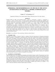
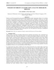
Fixed at flange only (Type A) Fixed at flange <strong>and</strong> web (Type B)<br />
Figure 4 : Lateral restra<strong>in</strong>t Type A <strong>and</strong> B at the beam end support<br />
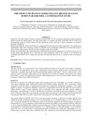
The test was stopped when buckl<strong>in</strong>g occurred, as determ<strong>in</strong>ed <strong>in</strong> the graph <strong>of</strong> moment versus lateral<br />
displacement. In the test, all beam specimens were found to be still <strong>in</strong> elastic state after the tests. Relationships<br />
between bend<strong>in</strong>g moment <strong>and</strong> lateral deflection were plotted. In general, the lateral deflection <strong>in</strong>crease l<strong>in</strong>early with<br />
the vertical bend<strong>in</strong>g moment. Then, the <strong>in</strong>crease becomes non-l<strong>in</strong>ear, followed by a stage when the deflection<br />
<strong>in</strong>crease monotonically.<br />
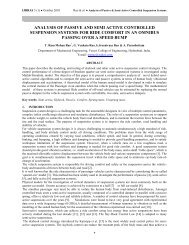
The value <strong>of</strong> lateral torsional buckl<strong>in</strong>g moment resistance was determ<strong>in</strong>ed from the <strong>in</strong>tersection <strong>of</strong> tangent<br />
<strong>of</strong> the first <strong>and</strong> second curve. The <strong>in</strong>tersection method was known as “knee jo<strong>in</strong>t” which has been used by other<br />
researchers [9,10] to determ<strong>in</strong>e the moment resistance <strong>of</strong> connection. The values <strong>of</strong> lateral torsional buckl<strong>in</strong>g<br />
resistance, Mb for all specimens were determ<strong>in</strong>ed when a “knee” shape was observed. In each graph, two tangent<br />
l<strong>in</strong>es were drawn <strong>and</strong> the <strong>in</strong>tersection <strong>of</strong> these two l<strong>in</strong>es gives the Mb value.<br />
The deflection from the midspan was used for the determ<strong>in</strong>ation <strong>of</strong> Mb. The Mb value for each beam was<br />
<strong>in</strong>dicated <strong>in</strong> each graph (Figure 5). The result <strong>of</strong> the experiment is presented <strong>in</strong> Table 1.<br />
Moment, M (kNm)<br />
10.00<br />
8.00<br />
6.00<br />
4.00<br />
2.00<br />
TWP3A(A)5m<br />
0.00<br />
0.00 1.00 2.00 3.00<br />
Lateral displacement (mm)<br />
Moment, M (kNm)<br />
235<br />
12.00<br />
10.00<br />
8.00<br />
6.00<br />
4.00<br />
TWP3A(B)5m<br />
2.00<br />
Mb=8.80 kNm Mb=10.30 kNm<br />
0.00<br />
0.00 0.20 0.40 0.60 0.80<br />
Lateral dispalcement (mm)<br />
Figure 5: Typical graphs for the determ<strong>in</strong>ation <strong>of</strong> Mb