CHAPTER 1 - International Journal of Research and Reviews in ...
CHAPTER 1 - International Journal of Research and Reviews in ...
CHAPTER 1 - International Journal of Research and Reviews in ...

You also want an ePaper? Increase the reach of your titles
YUMPU automatically turns print PDFs into web optimized ePapers that Google loves.
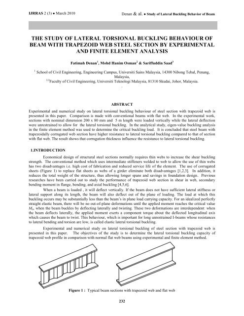
IJRRAS 2 (3) ● March 2010 Denan & al. ● Study <strong>of</strong> Lateral Buckl<strong>in</strong>g Behavior <strong>of</strong> Beam<br />
THE STUDY OF LATERAL TORSIONAL BUCKLING BEHAVIOUR OF<br />
BEAM WITH TRAPEZOID WEB STEEL SECTION BY EXPERIMENTAL<br />
AND FINITE ELEMENT ANALYSIS<br />
Fatimah Denan 1 , Mohd Hanim Osman 2 & Sariffudd<strong>in</strong> Saad 3<br />
1 School <strong>of</strong> Civil Eng<strong>in</strong>eer<strong>in</strong>g, Eng<strong>in</strong>eer<strong>in</strong>g Campus, Universiti Sa<strong>in</strong>s Malaysia, 14300 Nibong Tebal, Penang,<br />
Malaysia,<br />
2,3 Faculty <strong>of</strong> Civil Eng<strong>in</strong>eer<strong>in</strong>g, Universiti Teknologi Malaysia, 81310 Skudai, Johor, Malaysia.<br />
.<br />
ABSTRACT<br />
Experimental <strong>and</strong> numerical study on lateral torsional buckl<strong>in</strong>g behaviour <strong>of</strong> steel section with trapezoid web is<br />
presented <strong>in</strong> this paper. Comparison is made with conventional beams with flat web. In the experimental work,<br />
sections with nom<strong>in</strong>al dimension 200 x 80 mm <strong>and</strong> 5 m length were loaded vertically while the lateral deflection<br />
were unrestra<strong>in</strong>ed to allow for the lateral torsional buckl<strong>in</strong>g. In the analytical study, eigen-value buckl<strong>in</strong>g analysis<br />
<strong>in</strong> the f<strong>in</strong>ite element method was used to determ<strong>in</strong>e the critical buckl<strong>in</strong>g load. It is concluded that steel beam with<br />
trapezoidally corrugated web section have higher resistance to lateral torsional buckl<strong>in</strong>g compared to that <strong>of</strong> section<br />
with flat web. The result shows that corrugation thickness <strong>in</strong>fluence the resistance to lateral torsional buckl<strong>in</strong>g.<br />
1.INTRODUCTION<br />
Economical design <strong>of</strong> structural steel sections normally requires th<strong>in</strong> webs to <strong>in</strong>crease the shear buckl<strong>in</strong>g<br />
strength. The conventional method which uses <strong>in</strong>termediate stiffeners welded to web to allow the use <strong>of</strong> th<strong>in</strong> webs<br />
has two disadvantages i.e. high cost <strong>of</strong> fabrication <strong>and</strong> reduced service life <strong>of</strong> the element. The use <strong>of</strong> corrugated<br />
sheets (Figure 1) to replace flat sheets as webs <strong>of</strong> a girder elim<strong>in</strong>ate both disadvantages [1,2,3]. In addition, it<br />
reduces the total weight <strong>of</strong> the structure, thus allow<strong>in</strong>g longer spans <strong>and</strong> sav<strong>in</strong>gs <strong>in</strong> foundation design. Previous<br />
researches have been carried out to study the performance <strong>of</strong> trapezoid web section <strong>in</strong> shear <strong>in</strong> web, secondary<br />
bend<strong>in</strong>g moment <strong>in</strong> flange, bend<strong>in</strong>g, <strong>and</strong> axial buckl<strong>in</strong>g [4,5,6].<br />
When a beam is loaded , it will deflect vertically. If the beam does not have sufficient lateral stiffness or<br />
lateral support along its length, the beam will also deflect out <strong>of</strong> the plane <strong>of</strong> load<strong>in</strong>g. The load at which this<br />
buckl<strong>in</strong>g occurs may be substantially less than the beam‟s <strong>in</strong> plane load carry<strong>in</strong>g capacity. For an idealized perfectly<br />
straight elastic beam, there will be no out-<strong>of</strong>-plane deformations until the applied moment reaches the critical value<br />
Mb, when the beam buckles by deflect<strong>in</strong>g laterally <strong>and</strong> twist<strong>in</strong>g. These two deformations are <strong>in</strong>terdependent: when<br />
the beam deflects laterally, the applied moment exerts a component torque about the deflected longitud<strong>in</strong>al axis<br />
which causes the beam to twist. This behaviour, which is important for long unrestra<strong>in</strong>ed I-beams whose resistances<br />
to lateral bend<strong>in</strong>g <strong>and</strong> torsion are low, is called elastic lateral torsional buckl<strong>in</strong>g.<br />
Experimental <strong>and</strong> numerical study on lateral torsional buckl<strong>in</strong>g <strong>of</strong> steel section with trapezoid web is<br />
presented <strong>in</strong> this paper. The objectives <strong>of</strong> the study is to determ<strong>in</strong>e the lateral torsional buckl<strong>in</strong>g capacity <strong>of</strong><br />
trapezoid web pr<strong>of</strong>ile <strong>in</strong> comparison with normal flat web beams us<strong>in</strong>g experimental <strong>and</strong> f<strong>in</strong>ite element method.<br />
Figure 1 : Typical beam sections with trapezoid web <strong>and</strong> flat web<br />
232
IJRRAS 2 (3) ● March 2010 Denan & al. ● Study <strong>of</strong> Lateral Buckl<strong>in</strong>g Behavior <strong>of</strong> Beam<br />
2. EXPERIMENTAL STUDY<br />
2.1 Test procedure<br />
Lateral torsional buckl<strong>in</strong>g tests were conducted on three sets <strong>of</strong> beams, each set consists <strong>of</strong> two specimens i.e.<br />
sections with trapezoid web numbered as TWP3 (TWP3A <strong>and</strong> TWP3B), trapezoid web pr<strong>of</strong>ile TWP4 (TWP4A <strong>and</strong><br />
TWP4B) <strong>and</strong> flat web FW3 (FW3A <strong>and</strong> FW3B). The difference between TWP3 <strong>and</strong> TWP4 is <strong>in</strong> their web<br />
corrugation thickness, where TWP3 has full corrugation thickness (hr = B) while TWP4 has only half corrugation<br />
(hr = 0.5B).<br />
The test was designed based on the test method by Dirk [7] <strong>and</strong> Sal<strong>in</strong>a [8]. Figure 2 shows the diagrammatic view<br />
<strong>of</strong> the test set-up. The photograph is shown <strong>in</strong> Figure 3. A po<strong>in</strong>t load was loaded at mid span <strong>of</strong> the specimen<br />
through a specially designed load<strong>in</strong>g device. The L-shape roller bear<strong>in</strong>g guide was used to ensure that the jack<br />
always seated on a horizontal surface so that the direction <strong>of</strong> the load<strong>in</strong>g was kept vertical under <strong>in</strong>creas<strong>in</strong>g load<strong>in</strong>g.<br />
The roller on the top flange under the load<strong>in</strong>g was used to ensure that there was no horizontal restra<strong>in</strong>t that might<br />
<strong>in</strong>habit lateral buckl<strong>in</strong>g dur<strong>in</strong>g load<strong>in</strong>g.<br />
Two types <strong>of</strong> lateral restra<strong>in</strong>t at the support were used, i.e. type A <strong>and</strong> type B. For type A, the bottom flange <strong>of</strong> the<br />
beam at both ends were fixed, whilst for type B, the bottom flange <strong>and</strong> web which were both restra<strong>in</strong>ed from deflect<br />
laterally. It is shown <strong>in</strong> Figure 4.<br />
Beam specimen<br />
fixed at flange<br />
Test frame<br />
Beam specimen<br />
Load actuator<br />
Load cell<br />
Ch 1<br />
Ch 2<br />
A<br />
Lateral deflection transducer<br />
Ch 3<br />
A<br />
233<br />
Load actuator<br />
Load cell<br />
Ch Roller4<br />
Ch 5<br />
fixed at flange<br />
(a): The overall view <strong>of</strong> the test set up<br />
L-Shape roller<br />
bear<strong>in</strong>g guide<br />
(b): Details <strong>of</strong> the load<strong>in</strong>g device<br />
Figure 2: Test set-up <strong>and</strong> the load<strong>in</strong>g device<br />
Lateral deflection<br />
transducer
IJRRAS 2 (3) ● March 2010 Denan & al. ● Study <strong>of</strong> Lateral Buckl<strong>in</strong>g Behavior <strong>of</strong> Beam<br />
For each type <strong>of</strong> beam, two different spans were used i.e 4000 mm <strong>and</strong> 5000 mm. Displacement transducers were<br />
placed at five different locations to measure the lateral deflection <strong>of</strong> the beams. Loads were applied gradually,<br />
with the <strong>in</strong>crements <strong>of</strong> 1.0 kN. The displacement was recorded at each <strong>in</strong>crement. The lateral displacements <strong>of</strong><br />
beam specimens were measured at 400 mm (left <strong>and</strong> right) from mid span <strong>of</strong> the beam (for top <strong>and</strong> bottom<br />
flange) <strong>and</strong> also at the centre <strong>of</strong> the web.<br />
(a) : The overall view <strong>of</strong> the test beam<br />
(b) Positions <strong>of</strong> vertical <strong>and</strong> lateral transducers<br />
Figure 3 : The test<strong>in</strong>g rig <strong>and</strong> load<strong>in</strong>g at mid span<br />
234
IJRRAS 2 (3) ● March 2010 Denan & al. ● Study <strong>of</strong> Lateral Buckl<strong>in</strong>g Behavior <strong>of</strong> Beam<br />
Fixed at flange only (Type A) Fixed at flange <strong>and</strong> web (Type B)<br />
Figure 4 : Lateral restra<strong>in</strong>t Type A <strong>and</strong> B at the beam end support<br />
The test was stopped when buckl<strong>in</strong>g occurred, as determ<strong>in</strong>ed <strong>in</strong> the graph <strong>of</strong> moment versus lateral<br />
displacement. In the test, all beam specimens were found to be still <strong>in</strong> elastic state after the tests. Relationships<br />
between bend<strong>in</strong>g moment <strong>and</strong> lateral deflection were plotted. In general, the lateral deflection <strong>in</strong>crease l<strong>in</strong>early with<br />
the vertical bend<strong>in</strong>g moment. Then, the <strong>in</strong>crease becomes non-l<strong>in</strong>ear, followed by a stage when the deflection<br />
<strong>in</strong>crease monotonically.<br />
The value <strong>of</strong> lateral torsional buckl<strong>in</strong>g moment resistance was determ<strong>in</strong>ed from the <strong>in</strong>tersection <strong>of</strong> tangent<br />
<strong>of</strong> the first <strong>and</strong> second curve. The <strong>in</strong>tersection method was known as “knee jo<strong>in</strong>t” which has been used by other<br />
researchers [9,10] to determ<strong>in</strong>e the moment resistance <strong>of</strong> connection. The values <strong>of</strong> lateral torsional buckl<strong>in</strong>g<br />
resistance, Mb for all specimens were determ<strong>in</strong>ed when a “knee” shape was observed. In each graph, two tangent<br />
l<strong>in</strong>es were drawn <strong>and</strong> the <strong>in</strong>tersection <strong>of</strong> these two l<strong>in</strong>es gives the Mb value.<br />
The deflection from the midspan was used for the determ<strong>in</strong>ation <strong>of</strong> Mb. The Mb value for each beam was<br />
<strong>in</strong>dicated <strong>in</strong> each graph (Figure 5). The result <strong>of</strong> the experiment is presented <strong>in</strong> Table 1.<br />
Moment, M (kNm)<br />
10.00<br />
8.00<br />
6.00<br />
4.00<br />
2.00<br />
TWP3A(A)5m<br />
0.00<br />
0.00 1.00 2.00 3.00<br />
Lateral displacement (mm)<br />
Moment, M (kNm)<br />
235<br />
12.00<br />
10.00<br />
8.00<br />
6.00<br />
4.00<br />
TWP3A(B)5m<br />
2.00<br />
Mb=8.80 kNm Mb=10.30 kNm<br />
0.00<br />
0.00 0.20 0.40 0.60 0.80<br />
Lateral dispalcement (mm)<br />
Figure 5: Typical graphs for the determ<strong>in</strong>ation <strong>of</strong> Mb
IJRRAS 2 (3) ● March 2010 Denan & al. ● Study <strong>of</strong> Lateral Buckl<strong>in</strong>g Behavior <strong>of</strong> Beam<br />
Table 1 : Test results <strong>of</strong> Mb for beams with normal flat web <strong>and</strong> beams with trapezoid web pr<strong>of</strong>ile<br />
Span <strong>of</strong><br />
beam<br />
(mm)<br />
Beam mark Support type „A‟ Support type „B‟<br />
Mb<br />
kNm<br />
Average<br />
Mb<br />
kNm<br />
236<br />
Mb<br />
kNm<br />
Average<br />
Mb<br />
kNm<br />
5000 TWP3A 8.80 9.00 10.30 10.80<br />
TWP3B 9.20 11.30<br />
TWP4A 8.00 8.20 9.00 9.25<br />
TWP4B 8.40 9.50<br />
FW3A 7.10 7.05 8.20 8.55<br />
FW3B 7.00 8.90<br />
4000 TWP3A 9.50 9.65 11.00 11.20<br />
TWP3B 9.80 11.40<br />
TWP4A 8.90 9.10 9.20 9.60<br />
TWP4B 9.30 10.00<br />
From the table, it is observed that :<br />
FW3A 8.10 8.30 8.50 8.65<br />
FW3B 8.50 8.80<br />
(i) Beams with flat webs <strong>and</strong> 5 m have the average <strong>of</strong> lateral torsional buckl<strong>in</strong>g moment, Mb lower than that <strong>of</strong><br />
beam 4 m, for each <strong>of</strong> the Type A <strong>and</strong> B support. The same f<strong>in</strong>d<strong>in</strong>g for TWP3 <strong>and</strong> TWP4 was obta<strong>in</strong>ed.<br />
(ii) As expected, the beams with Type B support has higher Mb value that those with Type A support for both<br />
spans.<br />
(iii) TWP section perform better than that <strong>of</strong> flat web <strong>in</strong> terms <strong>of</strong> lateral torsional buckl<strong>in</strong>g moment resistance.<br />
(iv) The beam with trapezoid web pr<strong>of</strong>ile section with full shape corrugation (hr =B) are better than the beam<br />
with trapezoid web pr<strong>of</strong>ile section with half shape (hr =0.5B) <strong>and</strong> flat web <strong>in</strong> their lateral torsional buckl<strong>in</strong>g<br />
moment resistance.<br />
The higher resistance to lateral torsional buckl<strong>in</strong>g is due to the higher moment <strong>of</strong> <strong>in</strong>ertia about m<strong>in</strong>or axis, Iy for the<br />
section with trapezoid web pr<strong>of</strong>ile. The m<strong>in</strong>or axis moment <strong>of</strong> <strong>in</strong>ertia was studied by the author [11], <strong>and</strong> the<br />
formulation for the Iy value has been developed based on experimental <strong>and</strong> analytical study.<br />
3. F<strong>in</strong>ite Element Study On Lateral Torsional Buckl<strong>in</strong>g By F<strong>in</strong>ite Element Method<br />
In this study, all models were assumed to buckle under perfect conditions, where there is no <strong>in</strong>itial<br />
imperfectness <strong>and</strong> eccentric load. The buckl<strong>in</strong>g moments were then compared with result obta<strong>in</strong>ed from test<strong>in</strong>g .<br />
Eigenvalue analysis <strong>of</strong> LUSAS Modeller was used to determ<strong>in</strong>e the buckl<strong>in</strong>g loads.<br />
A l<strong>in</strong>ear buckl<strong>in</strong>g analysis is a useful technique that can be applied to relatively stiff structures to estimate the<br />
maximum load that can be supported prior to structural <strong>in</strong>stability or collapse. The assumptions used <strong>in</strong> l<strong>in</strong>ear<br />
buckl<strong>in</strong>g analysis are that the l<strong>in</strong>ear stiffness matrix does not change prior to buckl<strong>in</strong>g <strong>and</strong> that the stress stiffness<br />
matrix is simply a multiple <strong>of</strong> its <strong>in</strong>itial value.
IJRRAS 2 (3) ● March 2010 Denan & al. ● Study <strong>of</strong> Lateral Buckl<strong>in</strong>g Behavior <strong>of</strong> Beam<br />
3.1 Modell<strong>in</strong>g<br />
LUSAS models are def<strong>in</strong>ed <strong>in</strong> terms <strong>of</strong> geometric features that must be subdivided <strong>in</strong>to f<strong>in</strong>ite elements for<br />
solution. This process <strong>of</strong> sub division is called mesh<strong>in</strong>g. Mesh datasets conta<strong>in</strong> <strong>in</strong>formation about element types,<br />
element discretisation <strong>and</strong> mesh type. The I-beam models were assigned ungraded mild steel for its material<br />
property with Young‟s modulus, E= 209x10 3 N/mm 2 , shear modulus, G = 79x10 3 N/mm 2 <strong>and</strong> Poisson ratio <strong>of</strong> 0.3.<br />
The beams are simply supported <strong>and</strong> unrestra<strong>in</strong>ed laterally.<br />
The convergence <strong>of</strong> the mesh was established by <strong>in</strong>dependently <strong>in</strong>creas<strong>in</strong>g the mesh density <strong>in</strong> each part <strong>of</strong><br />
the model beam section. The model was also analysis with <strong>in</strong>creased mesh density <strong>in</strong> all parts <strong>of</strong> the section<br />
simultaneously, <strong>and</strong> with higher-order elements (QSL8).<br />
3.2 Eigenvalue Buckl<strong>in</strong>g Analysis<br />
The ma<strong>in</strong> objective <strong>in</strong> the eigenvalue buckl<strong>in</strong>g analysis is to obta<strong>in</strong> the critical buckl<strong>in</strong>g load, by solv<strong>in</strong>g the<br />
associated eigenvalue problem. In LUSAS, there are two methods to obta<strong>in</strong> <strong>in</strong>formation regard<strong>in</strong>g buckl<strong>in</strong>g loads<br />
<strong>and</strong> their respective deformation mode i.e. The l<strong>in</strong>ear eigenvalue buckl<strong>in</strong>g analysis <strong>and</strong> the full geometrically nonl<strong>in</strong>ear<br />
analysis. Figure 6 show a typical buckl<strong>in</strong>g shape <strong>in</strong> Mode 1.<br />
Y<br />
X<br />
Z<br />
Figure 6 : The buckl<strong>in</strong>g shape mode 1<br />
Modes 1,2, <strong>and</strong> 3 represents the buckl<strong>in</strong>g shape <strong>of</strong> the element. In this study the result <strong>of</strong> mode one would<br />
be considered; because it was found that all the beam specimen failed <strong>in</strong> the tests due to this mode. This is also<br />
because mode one is the least value. It will be unrealistic to choose the higher modes 2 <strong>and</strong> 3 to get the critical<br />
buckl<strong>in</strong>g load. The resulted eigenvalues are actually the load factors to be multiplied to the applied load<strong>in</strong>g, to obta<strong>in</strong><br />
critical buckl<strong>in</strong>g load. The eigenvalue buckl<strong>in</strong>g analysis <strong>in</strong> LUSAS Modeller will provide both local <strong>and</strong> global<br />
buckl<strong>in</strong>g modes. Eng<strong>in</strong>eer<strong>in</strong>g judgment is necessary to determ<strong>in</strong>e which buckl<strong>in</strong>g mode is the most critical <strong>in</strong> order<br />
to select the appropriate buckl<strong>in</strong>g load factor. It is, <strong>of</strong> course possible to visually exam<strong>in</strong>e the resultant modes <strong>in</strong><br />
LUSAS Modeller.<br />
237
IJRRAS 2 (3) ● March 2010 Denan & al. ● Study <strong>of</strong> Lateral Buckl<strong>in</strong>g Behavior <strong>of</strong> Beam<br />
3.3 Result <strong>and</strong> Discussion.<br />
The results <strong>of</strong> Mb are summarized <strong>in</strong> Table 2. In addition, the Mb value derived from the design calculation is given<br />
for each beam. The method <strong>of</strong> calculat<strong>in</strong>g the design Mb value is also given <strong>in</strong> BS 5950:Part1:2000, by neglect<strong>in</strong>g<br />
the contribution <strong>of</strong> web. It can be summarized as follow:<br />
The critical buckl<strong>in</strong>g loads <strong>and</strong> the lateral torsional buckl<strong>in</strong>g moments results <strong>of</strong> eigenvalue analysis theory<br />
calculation for trapezoid web pr<strong>of</strong>ile <strong>and</strong> flat web are presented <strong>in</strong> Table 4, for both type A <strong>and</strong> type B support. It is<br />
shown that, as expected, as the lengths <strong>of</strong> the two beams with trapezoid web pr<strong>of</strong>ile <strong>in</strong>crease, the lateral torsional<br />
buckl<strong>in</strong>g moment decreases. It is found that, trapezoid web pr<strong>of</strong>ile sections need higher load to buckle compared to<br />
flat web. This is because <strong>of</strong> the higher value <strong>of</strong> Iy for the TWP section compared to the flat web section [11].<br />
In terms <strong>of</strong> the effect <strong>of</strong> corrugation shape, the results show that web with full corrugation (TWP3 ; hr = B) have a<br />
higher resistance to lateral torsional buckl<strong>in</strong>g compared to that <strong>of</strong> the half corrugation shape (TWP4 ; hr = 0.5B) .<br />
As a conclusion, trapezoid web pr<strong>of</strong>ile section have higher resistance <strong>in</strong> lateral torsional buckl<strong>in</strong>g behaviour <strong>and</strong><br />
hence suitable for structural applications.<br />
Table 2 : Percentage difference <strong>of</strong> Mb for beams with normal flat web <strong>and</strong> beams with trapezoid web pr<strong>of</strong>ile (f<strong>in</strong>ite<br />
element analysis).<br />
Support Span<br />
Mb<br />
Support<br />
Type A<br />
Support<br />
Type B<br />
(mm)<br />
238<br />
Mb<br />
TWP3 TWP4 (FW)<br />
(design)<br />
6000 5.84 5.54 3.70 3.15<br />
5000 7.05 6.45 4.09 3.85<br />
4000 8.30 7.81 4.39 4.73<br />
3500 9.35 8.75 4.40 5.51<br />
6000 11.62 9.75 7.23 3.32<br />
5000 14.35 11.28 8.87 8.60<br />
4000 15.41 13.79 11.50 10.96<br />
3500 15.66 15.05 13.43 13.08<br />
Figure 7 shows the comparison between the TWP3, TWP4 <strong>and</strong> FW <strong>in</strong> their lateral torsional buckl<strong>in</strong>g<br />
resistance for Type A support. Both set <strong>of</strong> results show a similar trend i.e as the beam length <strong>in</strong>creases, the buckl<strong>in</strong>g<br />
moment decreases. In all beam cases, the f<strong>in</strong>ite element prediction are more than that <strong>of</strong> the test .<br />
For support Type B, the beam length <strong>in</strong>creases, the buckl<strong>in</strong>g moment decreases. For all specimens, the<br />
buckl<strong>in</strong>g moment results from the f<strong>in</strong>ite element predictions are bigger than that <strong>of</strong> the test results for all lengths <strong>of</strong><br />
beams.<br />
Mb (kNm)b<br />
10<br />
8<br />
6<br />
4<br />
2<br />
0<br />
Type A<br />
3000 4000 5000 6000<br />
Span<br />
TWP3<br />
TWP4<br />
(FW)<br />
Design
IJRRAS 2 (3) ● March 2010 Denan & al. ● Study <strong>of</strong> Lateral Buckl<strong>in</strong>g Behavior <strong>of</strong> Beam<br />
Mb (kNm)<br />
Type B<br />
18<br />
16<br />
14<br />
12<br />
10<br />
8<br />
6<br />
4<br />
2<br />
0<br />
3000 4000 5000 6000<br />
Span (m)<br />
Figure 7 : Buckl<strong>in</strong>g moment resistance for different span<br />
239<br />
TWP3<br />
TWP4<br />
(FW)<br />
Design<br />
Figure 7 show that as length <strong>in</strong>creased the value <strong>of</strong> Mb decreased. In both figures, comparison between<br />
different corrugation ratio shows that the value <strong>of</strong> Mb for TWP3 (half-corrugation) is higher than TWP4 (fullcorrugation).<br />
The overall observation shows that the result from the f<strong>in</strong>ite element analysis is higher than the test for<br />
support Type B but not for the Type A support. In comparison, <strong>in</strong> all cases, the value <strong>of</strong> Mb for f<strong>in</strong>ite element<br />
analysis <strong>and</strong> test<strong>in</strong>g are more than the value Mb from the design formula. In f<strong>in</strong>ite element analysis, the value <strong>of</strong> Mb<br />
at Type A support was less than Mb value from design formula. From both figures, comparison between different<br />
types <strong>of</strong> restra<strong>in</strong>t shows that Type B gives extra value than Type A support. This is <strong>in</strong> accordance to the theory,<br />
i.e.Type B support is supposed to get higher value <strong>of</strong> Mb than Type A. This is because <strong>of</strong> the specimen was more<br />
difficult to move <strong>in</strong> Type B support. Therefore, the value <strong>of</strong> Mb will be higher for Type B.<br />
4.0 CONCLUSION<br />
From the experimental <strong>and</strong> analytical study on the lateral torsional buckl<strong>in</strong>g on trapezoid web section, it can be<br />
concluded that :<br />
(1) Steel beam with trapezoidally corrugated web section have higher resistance to lateral torsional buckl<strong>in</strong>g.<br />
compared to that <strong>of</strong> section with flat web.<br />
(2) The result shows that corrugation thickness <strong>in</strong>fluence the resistance to lateral torsional buckl<strong>in</strong>g. Sections<br />
with thicker corrugation have higher resistance to lateral torsional buckl<strong>in</strong>g.<br />
(3) Higher value <strong>of</strong> moment <strong>of</strong> <strong>in</strong>ertia about m<strong>in</strong>or axis for the section with thicker corrugation contributes to<br />
the higher resistance to lateral torsional buckl<strong>in</strong>g.<br />
(4) F<strong>in</strong>ite element can be used to determ<strong>in</strong>e the elastic lateral torsional buckl<strong>in</strong>g moment <strong>of</strong> the section.<br />
5.0 ACKNOWLEDGEMENTS<br />
The first author wishes to thank Universiti Sa<strong>in</strong>s Malaysia (USM) for the f<strong>in</strong>ancial support dur<strong>in</strong>g the<br />
course <strong>of</strong> her research. This research was also made possible by the generous grant provided by the Construction<br />
Industry Development Board (CIDB). The assistance rendered by the technical staff <strong>of</strong> the Heavy Structures<br />
Laboratory, Faculty <strong>of</strong> Civil Eng<strong>in</strong>eer<strong>in</strong>g <strong>of</strong> Universiti Teknologi Malaysia is highly appreciated.
IJRRAS 2 (3) ● March 2010 Denan & al. ● Study <strong>of</strong> Lateral Buckl<strong>in</strong>g Behavior <strong>of</strong> Beam<br />
REFERENCES :<br />
1. Elgaaly M, Seshadri A, Steel built-up girders with trapezoidally corrugated webs,1988,Eng<strong>in</strong>eer<strong>in</strong>g journal,<br />
1 st .Quarter, London:AISC.<br />
2. Elgaaly,M, Seshadri,A, Hamilton, R.W, “Bend<strong>in</strong>g strength <strong>of</strong> steel beams with trapezoid corrugated webs”,<br />
ASCE <strong>Journal</strong> <strong>of</strong> Structural Eng<strong>in</strong>eer<strong>in</strong>g, 1997, Vol.123.<br />
3. Johnson,R.P <strong>and</strong> Caffola, J, “Local flange buckl<strong>in</strong>g <strong>in</strong> plate girders with corrugated webs”, Proceed<strong>in</strong>g<br />
Instn Civil Eng<strong>in</strong>eer<strong>in</strong>g Structures <strong>and</strong> Build<strong>in</strong>gs, 1997.<br />
4. Osman, M.H, “Shear buckl<strong>in</strong>g <strong>of</strong> trapezoid web pr<strong>of</strong>ile section”, <strong>International</strong> Conference on Numerical<br />
Method <strong>in</strong> Structural Eng<strong>in</strong>eer<strong>in</strong>g”, Indonesia, 2001.<br />
5. Osman, M.H, “Secondary bend<strong>in</strong>g moment <strong>in</strong> trapezoid web section”, Civil Eng<strong>in</strong>eer<strong>in</strong>g <strong>Research</strong> Sem<strong>in</strong>ar,<br />
Universiti Teknologi Malaysia, Johor, Bahru.<br />
6. Osman,M.H, C,H,Tan, “Axial buckl<strong>in</strong>g <strong>of</strong> column with trapezoid web”, Asia Pacific Structural Eng<strong>in</strong>eer<strong>in</strong>g<br />
Conference,2003, Johor Bahru, Malaysia.<br />
7. Dirk, P.P, “Lateral torsional buckl<strong>in</strong>g <strong>of</strong> <strong>of</strong> end notched steel beams”, <strong>International</strong> Colloquium on Stability<br />
<strong>of</strong> Structures under Static & Dynamic Loads, ACSE, 1977.<br />
8. Sal<strong>in</strong>a, J, “Lateral torsional buckl<strong>in</strong>g <strong>of</strong> beam with trapezoid web pr<strong>of</strong>ile”, Master thesis, Universiti<br />
Teknologi Malaysia, 2003.<br />
9. Anis, “Behaviour <strong>of</strong> connection <strong>of</strong> composite beam with trapezoid web pr<strong>of</strong>ile‟ PhD. Thesis, Universiti<br />
Teknologi Malaysia, 2007.<br />
10. Arizu,S ““Behaviour <strong>of</strong> connection <strong>of</strong> beam-column with trapezoid web pr<strong>of</strong>ile‟ PhD. Thesis, Universiti<br />
Teknologi Malaysia, 2007.<br />
11. Fatimah, D, “Moment <strong>of</strong> <strong>in</strong>ertia about m<strong>in</strong>or axis <strong>of</strong> steel sections with trapezoid web”, Technical Report,<br />
Steel Technology Centre, Universiti Teknologi Malaysia, 2007.<br />
Mb=10.00<br />
kNm<br />
240