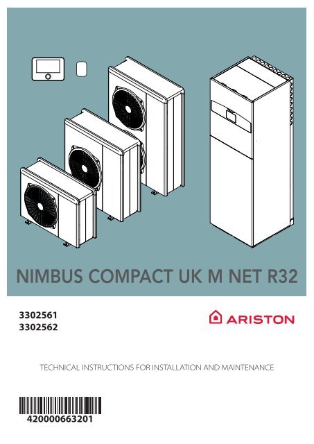
Nimbus Compact M NET R32 Installation Manual UK

You also want an ePaper? Increase the reach of your titles
YUMPU automatically turns print PDFs into web optimized ePapers that Google loves.
NIMBUS COMPACT <strong>UK</strong> M <strong>NET</strong> <strong>R32</strong><br />
3302561<br />
3302562<br />
TECHNICAL INSTRUCTIONS FOR INSTALLATION AND MAINTENANCE<br />
420000663201<br />
EN
<br />
Introduction<br />
Dear Madam,<br />
Dear Sir,<br />
thank you for choosing the NIMBUS COMPACT <strong>UK</strong> M <strong>NET</strong><br />
<strong>R32</strong> ARISTON system.<br />
This manual was drawn up with the aim of informing you on<br />
how to install, use and maintain the NIMBUS COMPACT <strong>UK</strong> M<br />
<strong>NET</strong> <strong>R32</strong> system, in order to enable you to optimally use all the<br />
functions.<br />
This installation manual along with the user manual should be<br />
left with the product after installation for future reference.<br />
Store this booklet, as it contains all the necessary information<br />
regarding the product following its initial installation.<br />
To find the nearest Technical Assistance Service and to consult<br />
the multimedia copy of the documentation, you can connect<br />
to the Internet website www.ariston.com.<br />
Please also refer to the Warranty Certificate that you will find<br />
inside the packaging, or which was handed to you by the installer.<br />
Symbols used throughout this manual<br />
and their meaning<br />
i<br />
a<br />
Warranty<br />
WARNING Indicates important information<br />
and particularly delicate operations.<br />
WARNING: DANGER Indicates actions that,<br />
if not performed correctly, can lead to general<br />
injuries or malfunctions or material damages<br />
to the appliance; they therefore require<br />
special attention and adequate training.<br />
The ARISTON product is covered by a conventional warranty,<br />
which takes effect from the date of purchase of the appliance.<br />
For the warranty conditions, refer to the warranty certificate accompanying<br />
the product.<br />
Compliance<br />
The CE marking applied to the appliance certifies that it conforms<br />
with the essential requirements of the following European<br />
Directives:<br />
– 2014/30/EU (Electromagnetic Compatibility Directive)<br />
– 2014/35/EU (Low Voltage Directive)<br />
– RoHS 3 2015/863/EU on restrictions regarding the use<br />
of certain hazardous substances in electrical and electronic<br />
appliances (EN IEC 63000:2018)<br />
– Regulation (EU) no. 813/2013 relative to ecodesign (no.<br />
2014/C 207/02 - transitional methods of measurement<br />
and calculation)<br />
– 2014/68/EU (PED)<br />
The <strong>UK</strong>CA marking applied to the appliance certifies that it<br />
conforms with the essential requirements of the following<br />
Regulations:<br />
– Electrical Equipment (Safety) Regulations 2016 (S.I. 2016<br />
No 1101, as amended)<br />
– Ecodesign for Energy-Related Products and Energy<br />
Information Regulations 2019 (S.I. 2019 No 539, as<br />
amended)<br />
– Pressure Equipment (Safety) Regulations SI 2016 no.<br />
1105, as amended<br />
– Electromagnetic Compatibility Regulations 2016 (S.I.<br />
2016 No. 1091, as amended)<br />
– The Restriction of the Use of Certain Hazardous Substances<br />
in Electrical and Electronic Equipment Regulations<br />
2012 (S.I. 2012 No. 3031, as amended)<br />
According to BS EN 12897:2016, the product complies with the<br />
following requirements.<br />
– The Building Regulations 2010 (S.I. 2010 No. 2214), as<br />
amended<br />
– The Water Supply (Water Fittings) Regulations 1999 (S.I.<br />
1999 No. 1148), as amended<br />
Disposal<br />
PRODUCT CONFORMING TO:<br />
– EU DIRECTIVE 2012/19/EU<br />
– Italian Legislative Decree 49/2014<br />
pursuant to Art. 26 of Legislative<br />
Decree no. 49 of 14 March 2014,<br />
“Implementation of Directive<br />
2012/19/UE on waste of electrical<br />
and electronic equipment (WEEE)”<br />
– <strong>UK</strong> Waste Electrical and Electronic<br />
Equipment Regulations 2013 S.I.<br />
2013 No. 3113<br />
The barred wheeled bin symbol appearing on the appliance or<br />
on its packaging indicates that the product must be collected<br />
separately from other waste at the end of its useful life.<br />
The user must therefore deliver the decommissioned product<br />
to an appropriate local facility for separate collection of electrotechnical<br />
and electronic waste. Alternatively, the appliance to<br />
be scrapped can be delivered to the dealer when purchasing a<br />
new equivalent appliance.<br />
Proper separated collection of the decommissioned appliance<br />
for its subsequent recycling, treatment and eco-compatible<br />
disposal helps to prevent negative effects on the environment<br />
and human health, besides encouraging reuse and/or recycling<br />
of its constituent materials.<br />
2 / EN
<br />
Contents<br />
1. Safety advices<br />
1.1 General warnings and safety instructions 4<br />
1.2 Use of the <strong>R32</strong> refrigerant 6<br />
1.3 Symbols affixed to the appliance 7<br />
2. Description of the system<br />
2.1 Outdoor unit (ODU) 8<br />
2.1.1 Structure 8<br />
2.1.2 Dimensions and weights 9<br />
2.1.3 Hydraulic and drainage fittings 10<br />
2.1.4 Accessories 10<br />
2.2 Indoor unit (IDU) 11<br />
2.2.1 Structure 11<br />
2.2.2 Dimensions and weights 13<br />
2.2.3 Hydraulic and drainage fittings 13<br />
2.3 Operational limits 14<br />
2.3.1 Compressor frequency table 14<br />
2.3.2 DHW Safety device intervention order 14<br />
2.4 Identification 15<br />
2.5 System interface SENSYS HD 16<br />
2.5.1 Technical data 17<br />
2.6 External probe 17<br />
3. <strong>Installation</strong><br />
3.1 Preliminary warnings 18<br />
3.2 Receiving the product 19<br />
3.3 Installing the outdoor unit 19<br />
3.3.1 Place of installation 19<br />
3.3.2 Noise level 20<br />
3.3.3 Handling 20<br />
3.3.4 <strong>Installation</strong> 21<br />
3.3.5 Arranging the connections 22<br />
3.3.6 Installing the accessory kit 22<br />
3.4 Installing the indoor unit 23<br />
3.4.1 Place of installation 23<br />
3.4.2 Handling 24<br />
4. Hydraulic connections<br />
4.1 Indoor unit hydraulic connections 25<br />
4.1.1 Safety valve drain 26<br />
4.1.2 Minimum water content 26<br />
4.1.3 Expansion vessel 26<br />
4.1.4 Rated and minimum flow rate 26<br />
4.1.5 Available pressure 27<br />
4.1.6 Characteristics of the supply water 28<br />
4.1.7 Filling the system 28<br />
4.2 <strong>Installation</strong> of the Hydraulic KIT 29<br />
4.2.1 Safety inlet assembly 29<br />
4.2.2 Exspansion vessel 29<br />
4.2.3 Tundish 29<br />
4.2.4 Safety device connection 29<br />
4.2.5 Hydraulic connections 30<br />
4.3 Example of schematic hydraulic diagram 31<br />
5. Electrical connections<br />
5.1 Outdoor unit electrical connections 35<br />
5.2 Indoor unit electrical connections 37<br />
5.3 Example of electrical connection between<br />
indoor and outdoor units 40<br />
5.4 Installing the system interface 41<br />
5.4.1 Wall installation 41<br />
5.4.2 On-board installation 41<br />
5.5 Installing the Light Gateway 43<br />
6. Commissioning<br />
6.1 Checking for electrical dispersions and gas<br />
leakages 45<br />
6.1.1 Electrical safety checks 45<br />
6.1.2 Check for gas leakages 45<br />
6.2 Preliminary checks 45<br />
6.3 Initial start-up 46<br />
6.3.1 Start-up procedure 46<br />
6.4 Basic functions 47<br />
6.5 Access to technical area 47<br />
6.6 Technical parameters 48<br />
6.7 Temperature adjustment 58<br />
6.8 Standard SG ready 62<br />
6.9 Parameter table 63<br />
7. Service<br />
7.1 Cleaning and inspecting the indoor unit 74<br />
7.2 Cleaning and inspecting the outdoor unit 74<br />
7.3 Error list 75<br />
8. Decommissioning<br />
8.1 Draining the circuit and recovering the<br />
refrigerant 78<br />
8.2 Disposal 79<br />
9. Technical information<br />
9.1 Data plate 80<br />
9.2 Technical data table for refrigerant 80<br />
10. Annexes<br />
EN / 3
1. Safety advices<br />
1.1 General warnings and safety instructions<br />
i<br />
i<br />
i<br />
i<br />
This manual is the property of ARISTON and it<br />
is forbidden to reproduce or transfer to third<br />
parties the contents of this document. All<br />
rights reserved. This document is an integral<br />
part of the product; make sure that it always<br />
accompanies the appliance, also when the<br />
latter is sold/transferred to another owner, so<br />
that it can be consulted by the user or by personnel<br />
authorised to perform maintenance<br />
and repairs.<br />
Read the information and warnings given in<br />
this manual in full; they are essential to the<br />
safe installation, use and maintenance of the<br />
product.<br />
It is forbidden to use this product for purposes<br />
and in conditions other than those specified<br />
here. The manufacturer shall not be held<br />
liable for any damages due to improper, incorrect<br />
or unreasonable use or due to failure<br />
to comply with the instructions and<br />
warnings contained in this manual.<br />
It is forbidden to use this product in combination<br />
with electrical and electronic appliances<br />
or with accessories not manufactured<br />
and/or not authorised by the manufacturer<br />
that can alter the conditions guaranteeing<br />
conformity to the legal requirements and/or<br />
the relevant technical regulations or that can<br />
alter the safety and/or operating conditions<br />
and/or performances of the product itself,<br />
thus invalidating the product’s conformity<br />
marking (e.g. CE mark or other conformity<br />
marks of the product).<br />
i<br />
i<br />
i<br />
i<br />
i<br />
i<br />
i<br />
i<br />
Safety advices<br />
In particular, it is forbidden to install on the<br />
proprietary BUS access port electrical and<br />
electronic appliances not manufactured<br />
and/or not authorised by the manufacturer.<br />
It is also forbidden to make changes to<br />
the product’s software programme for the<br />
above-mentioned reasons and for the potential<br />
consequences thereof, including the invalidation<br />
of the product’s conformity marking<br />
(e.g. CE mark or other conformity marks<br />
of the product).<br />
The manufacturer declines all liability deriving<br />
from the use of the product if the above<br />
warnings are not observed.<br />
All routine and extraordinary maintenance<br />
operations, such as breaking into the refrigerating<br />
circuit and opening of sealed<br />
components, must be carried exclusively by<br />
qualified personnel exclusively using original<br />
spare parts. The manufacturer is not liable for<br />
damage resulting from failure to observe this<br />
instruction, which may compromise the safety<br />
of the installation.<br />
Product dismantling and recycling operations<br />
must be carried out by qualified technical<br />
personnel.<br />
At all times the manufacturer’s maintenance<br />
and service guidelines shall be followed. If in<br />
doubt, consult the manufacturer’s technical<br />
department for assistance.<br />
Make sure the installation site and any systems<br />
to which the appliance must be connected<br />
comply with applicable regulations.<br />
The appliance is configured for connecting<br />
directly to the water mains.<br />
4 / EN
a<br />
a<br />
a<br />
a<br />
a<br />
a<br />
a<br />
When connecting the cooling system, avoid<br />
substances or gases other than the specified<br />
refrigerant from entering the unit. The<br />
presence of other gases or substances in the<br />
unit can reduce its performances and reliability,<br />
and also cause an abnormal pressure<br />
increase during the cooling cycle. This could<br />
lead to possible explosions and the resulting<br />
injuries.<br />
The appliance must be installed in a well-ventilated<br />
room having adequate dimensions as<br />
specified for the appliance’s operation.<br />
The Heat pump can be used by children older<br />
than 8 years and by people with reduced<br />
physical, sensory or mental abilities, or who<br />
lack adequate experience and the necessary<br />
knowledge, provided they are supervised or<br />
have been instructed on the safe use of the<br />
appliance and on the potential risks connected<br />
with it. Children must not play with the<br />
appliance. Any cleaning and maintenance<br />
which should be performed by the user must<br />
not be done by unsupervised children.<br />
For electrical interventions, observe the provisions<br />
of the national electrical standard,<br />
local rules, applicable regulations, and the<br />
instructions of the installation manual. It is<br />
necessary to use an independent circuit and<br />
a single power outlet. Do not connect other<br />
appliances to the same power outlet. An<br />
insufficient electrical capacity or defective<br />
electrical installation may lead to potential<br />
electrocution or fire.<br />
During the appliance installation phases, be<br />
careful not to damage the power cables or<br />
any existing piping.<br />
Perform all electrical connections using suitably-sized<br />
cables.<br />
Protect connection piping and cables so as<br />
to prevent damage to them.<br />
a<br />
a<br />
a a<br />
a<br />
a<br />
a<br />
a<br />
a<br />
Safety advices<br />
During all work procedures, wear individual<br />
protective clothing and equipment. Do not<br />
touch the installed product if barefoot and/<br />
or with any wet part of the body.<br />
Reset all safety and control functions affected<br />
by any work carried out on the appliance and<br />
make sure that they operate correctly before<br />
restarting it.<br />
If you notice a burnt smell or see smoke coming<br />
out of the device, disconnect it from the<br />
power supply, open all windows and contact<br />
the technician.<br />
Do not climb the outdoor unit.<br />
Do not leave the outdoor unit open, without<br />
its casing, for longer than strictly necessary<br />
for installation or maintenance.<br />
Do not leave flammable material in the vicinity<br />
of the system. Make sure that all components<br />
of the system are positioned as required<br />
by regulations.<br />
Do not start up the system if steam or dangerous<br />
powders are present in the installation<br />
room.<br />
Do not place fluid containers and other foreign<br />
objects on the indoor or outdoor units.<br />
Do not use the outdoor unit for treating<br />
water from industrial processes, swimming<br />
pools or domestic water. In such cases, to use<br />
the outdoor unit install a heat exchanger in<br />
an intermediate position.<br />
The removal of the product’s protective panels<br />
and all operations involving maintenance<br />
and connection of electrical equipment must<br />
be performed by qualified personnel.<br />
EN / 5
Safety advices<br />
1.2 Use of the <strong>R32</strong> refrigerant<br />
i<br />
a<br />
a<br />
a<br />
a<br />
a<br />
FLAMMABLE MATERIAL<br />
The <strong>R32</strong> refrigerant is odourless.<br />
This system contains fluorinated refrigerant.<br />
For specific information on the type and<br />
quantity of refrigerant, refer to the data plate.<br />
Always observe the national regulations on<br />
the use of refrigerant.<br />
Interventions on the refrigeration circuit<br />
must only be carried out by operators possessing<br />
a valid certification, issued by an accredited<br />
body, certifying their expertise in<br />
working with safely and in accordance with<br />
the specifications in force in the sector.<br />
No person carrying out work in relation to a<br />
refrigerating system which involves exposing<br />
any pipe work shall use any sources of ignition<br />
in such a manner that it may lead to the<br />
risk of fire or explosion.<br />
All possible ignition sources, including cigarette<br />
smoking, should be kept sufficiently far<br />
away from the site of installation, repairing,<br />
removing and disposal, during which refrigerant<br />
can possibly be released to the surrounding<br />
space.<br />
Prior to work taking place, the area around<br />
the equipment is to be surveyed to make<br />
sure that there are no flammable hazards or<br />
ignition risks. “No Smoking” signs shall be displayed.<br />
6 / EN
Safety advices<br />
1.3 Symbols affixed to the appliance<br />
Indoor unit (IDU)<br />
The appliance has the following symbols affixed to it:<br />
Outdoor unit (ODU)<br />
4<br />
3<br />
6<br />
7<br />
5<br />
2<br />
7<br />
1<br />
8<br />
9<br />
10<br />
11<br />
5<br />
7<br />
Fig. 1<br />
Reference<br />
Description<br />
7 Danger moving parts<br />
8 Danger flammable refrigerant<br />
9 Normative symbols for <strong>R32</strong> gas<br />
3<br />
4<br />
10<br />
000000000000<br />
Serial number<br />
Fig. 2<br />
11 Electrical precautions<br />
Reference<br />
Description<br />
1 Danger hot surface<br />
2 Do not touch<br />
3 Danger flammable refrigerant<br />
4 It is mandatory to read the manual<br />
5 Earthing symbol<br />
6 Tighten using 2 spanners<br />
7 The panel must be in place for the<br />
appliance’s intended operation. (*)<br />
(*) The inner label is only present for the 2-ZONE model<br />
EN / 7
Description of the system<br />
2. Description of the system<br />
2.1 Outdoor unit (ODU)<br />
2.1.1 Structure<br />
The outdoor unit supplied is one of the following models:<br />
– NIMBUS 35 M EXT <strong>R32</strong><br />
– NIMBUS 50 M EXT <strong>R32</strong><br />
– NIMBUS 80 M EXT <strong>R32</strong><br />
– NIMBUS 80 M-T EXT <strong>R32</strong><br />
– NIMBUS 120 M EXT <strong>R32</strong><br />
– NIMBUS 150 M EXT <strong>R32</strong><br />
– NIMBUS 120 M-T EXT <strong>R32</strong><br />
– NIMBUS 150 M-T EXT <strong>R32</strong><br />
9<br />
8<br />
7<br />
6<br />
5<br />
1<br />
2 3 4<br />
1 Fan<br />
2 Compressor<br />
3 Safety valve<br />
4 Plate heat exchanger<br />
5 Circulation pump<br />
6 Flowmeter<br />
7 Expansion valve<br />
8 4-way valve<br />
9 Deaerator<br />
Fig. 3<br />
i<br />
The images appearing in this manual are purely for illustration purposes. The appliance you have may differ<br />
slightly from the illustrations shown here. Always refer to the unit’s actual characteristics.<br />
8 / EN
Description of the system<br />
2.1.2 Dimensions and weights<br />
Outdoor unit (ODU)<br />
Weight [kg]<br />
NIMBUS M EXT <strong>R32</strong> 35 M - 50 M 66<br />
NIMBUS M EXT <strong>R32</strong> 80 M 91<br />
NIMBUS M EXT <strong>R32</strong> 80 M-T 104<br />
NIMBUS M EXT <strong>R32</strong> 120 M - 150 M 124<br />
NIMBUS M EXT <strong>R32</strong> 120 M-T - 150 M-T 131<br />
35 M - 50 M<br />
120 M & M-T 150 M & M-T<br />
1016 mm<br />
374 mm<br />
1016 mm 350 mm<br />
1506 mm<br />
756 mm<br />
670 mm<br />
Ø10 mm<br />
670 mm<br />
Ø10 mm<br />
383 mm<br />
383 mm<br />
80 M & M-T<br />
Fig. 4<br />
Fig. 6<br />
1016 mm<br />
374 mm<br />
1106 mm<br />
670 mm<br />
Ø10 mm<br />
383 mm<br />
Fig. 5<br />
EN / 9
Description of the system<br />
2.1.3 Hydraulic and drainage fittings<br />
89 mm<br />
71 mm<br />
G 1”F<br />
513 mm<br />
403 mm<br />
72 mm<br />
G 1”F<br />
Fig. 7<br />
1<br />
2<br />
Fig. 8<br />
1 Plumbing connections<br />
2 Electrical connections passage<br />
2.1.4 Accessories<br />
The outdoor unit can be equipped with the following accessories:<br />
– anti-freeze kit (recommended)<br />
– condensate collection tray<br />
– condensate collection tray heating element<br />
For the installation of the accessories, refer to the paragraph<br />
“Installing the accessory kit”<br />
10 / EN
Description of the system<br />
2.2 Indoor unit (IDU)<br />
2.2.1 Structure<br />
The indoor unit supplied is one of the following models:<br />
– NIMBUS FS-<strong>UK</strong> M <strong>R32</strong><br />
– NIMBUS FS-L-<strong>UK</strong> M <strong>R32</strong><br />
General structure<br />
The indoor unit is made up of two compartments that can be opened on the front to allow for accessing, inspecting and performing<br />
maintenance on the internal components.<br />
2<br />
6<br />
1<br />
21<br />
3<br />
5<br />
13<br />
20<br />
4<br />
19<br />
7<br />
8 11<br />
9<br />
10<br />
18<br />
14<br />
17<br />
12<br />
15<br />
14<br />
16<br />
1 Expansion vessel<br />
2 Heating element<br />
3 Automatic air relief valve (heating element)<br />
4 Immersion temperature sensor (flow)<br />
5 <strong>Manual</strong> reset safety thermostat<br />
6 Space heating flow<br />
7 Multifunctional magnetic filter<br />
8 Pressure gauge<br />
9 Safety valve<br />
10 Pressure transducer<br />
11 Automatic air relief valve (filter)<br />
Fig. 9<br />
12 Coil discharge<br />
13 Return from system<br />
14 Passive anode<br />
15 Indirect cylinder temperature sensor<br />
16 Indirect cylinder drainage valve with hose connector<br />
17 Temperature and pressure relief valve<br />
18 Storage active<br />
19 DHW flow<br />
20 Return to outdoor unit<br />
21 <strong>Manual</strong> air relief valve<br />
EN / 11
Description of the system<br />
Structure of the hydraulic part<br />
1<br />
Mod. 1Z<br />
2<br />
1 Space heating flow<br />
2 Motor-driven three-way valve<br />
Fig. 10<br />
12 / EN
Description of the system<br />
2.2.2 Dimensions and weights<br />
Indoor unit (IDU)<br />
Net weight<br />
[kg]<br />
Gross<br />
weight [kg]<br />
NIMBUS FS-<strong>UK</strong> M <strong>R32</strong> 127 307<br />
NIMBUS FS-L-<strong>UK</strong> M <strong>R32</strong> 127 307<br />
D - DHW recirculation 3/4<br />
E<br />
Domestic hot water inlet 3/4<br />
IN<br />
F<br />
Domestic hot water flow 3/4<br />
OUT<br />
G<br />
System return 1<br />
Z1<br />
IN<br />
H<br />
Delivery from heat pump 1<br />
A<br />
M T&P valve drain 1<br />
1818 mm<br />
A<br />
F<br />
G<br />
B<br />
E<br />
600 mm 612 mm<br />
C<br />
M<br />
Fig. 11<br />
H<br />
2.2.3 Hydraulic and drainage fittings<br />
1-ZONE configuration<br />
H<br />
552 mm<br />
360 mm<br />
300 mm<br />
240 mm<br />
211 mm<br />
Fig. 13<br />
Z1<br />
OUT<br />
B<br />
B<br />
A<br />
C<br />
D E F<br />
A<br />
G<br />
Z1<br />
IN<br />
A<br />
IN<br />
OUT<br />
Fig. 12<br />
Label Description Ø of fittings<br />
[inches]<br />
System flow 1<br />
Z1<br />
OUT<br />
1476 mm<br />
1425 mm<br />
1361 mm<br />
1305 mm<br />
890 mm<br />
B Safety valve drain 1<br />
C<br />
B<br />
Return to heat pump 1<br />
Fig. 14<br />
EN / 13
Description of the system<br />
2.3 Operational limits<br />
The following diagrams show the limits of the heat pump. The<br />
temperature difference between the delivery and return of the<br />
plate heat exchanger must be between 5°C and 8°C.<br />
Operating limits for space heating<br />
Output water temperature (°C)<br />
75<br />
70<br />
65 3<br />
60<br />
55<br />
50<br />
45<br />
40<br />
1<br />
35<br />
30<br />
25<br />
20<br />
2<br />
15<br />
10<br />
5<br />
0<br />
-35 -30 -25 -20 -15 -10 -5 0 5 10 15 20 25 30 35 40 45 50<br />
Outdoor air temperature (°C)<br />
Fig. 15<br />
1 Operation without restrictions<br />
2 Operation of the outdoor unit with possible capacity reduction<br />
3 Operation with back-up heating element necessary<br />
Operating limits for cooling<br />
Output water temperature (°C)<br />
25<br />
20<br />
15<br />
10<br />
5<br />
(10;23)<br />
(10;5)<br />
UF<br />
FC<br />
(43;23)<br />
(43;5)<br />
2.3.1 Compressor frequency table<br />
The maximum allowed frequency varies with the outdoor temperature.<br />
The values shown in the table refer to the following conditions:<br />
– Heating: air temperature < 0°C<br />
– Cooling: air temperature >30°C<br />
NIMBUS M EXT <strong>R32</strong><br />
35 M 50 M 80<br />
M &<br />
M-T<br />
120<br />
M &<br />
M-T<br />
150<br />
M &<br />
M-T<br />
Min frequency [Hz] 18 18 18 18 18<br />
Max frequency (heating)<br />
80 100 90 75 90<br />
[Hz]<br />
Max frequency (cooling)<br />
[Hz]<br />
65 80 70 57 70<br />
2.3.2 DHW Safety device intervention order<br />
To prevent excessively high temperatures and pressure inside<br />
the tank, the indoor unit is fitted with protection and control<br />
devices that will intervene in the following order:<br />
1 Thermostatic control device: this device, consisting of a<br />
sensor positioned on the DHW tank, switches off the heat<br />
source once the programmed set-point has been reached.<br />
2 Energy cut-out device: this device is a manual-reset<br />
thermostat and is positioned on the heating element of<br />
the technical circuit. The thermostat intervenes when a<br />
temperature of 85°C is reached. If it intervenes, it must be<br />
reset manually.<br />
3 Temperature and pressure relief valve: the tank is fitted<br />
with a T&P relief valve that intervenes in case of overtemperature<br />
(90-95°C) or overpressure (7 bar). Whenever<br />
the valve intervenes, the water flow it discharges could<br />
have a very high temperature.<br />
0<br />
0 5 10 15 20 25 30 35 40 45 50<br />
Outdoor air temperature (°C)<br />
UF:<br />
FC:<br />
underfloor heating<br />
fan coil<br />
Fig. 16<br />
Operating limits for indoor unit<br />
The indoor unit is designed for being installed only in indoor<br />
environments in which the following conditions occur:<br />
– Minimum temperature: 5°C<br />
– Maximum temperature: 30°C - R.H. 65%<br />
Operational limits<br />
– Minimum system water temperature: 5°C<br />
– Maximum system water temperature: 70°C<br />
– Cylinder maximum operating pressure: 0.6 MPa (6 bar)<br />
– Maximum inlet pressure of the safety inlet assembly: 1.2<br />
MPa (12 bar)<br />
– Hydraulic circuit maximum pressure: 0.3 MPa (3 bar)<br />
14 / EN
Description of the system<br />
2.4 Identification<br />
The indoor and outdoor units can be identified through the<br />
product identification plate marked with the serial number,<br />
model and main technical-performance characteristics.<br />
Indoor unit (IDU)<br />
1<br />
1 Identification plate<br />
Fig. 17<br />
Outdoor unit (ODU)<br />
1<br />
1 Identification plate<br />
Fig. 18<br />
EN / 15
Description of the system<br />
2.5 System interface SENSYS HD<br />
D<br />
E F G H<br />
10°<br />
Ve 4-GIU 12:30<br />
21° ,5<br />
° 18,0<br />
<br />
SALOTTO<br />
5 °C<br />
30<br />
1,5 bar<br />
I<br />
L<br />
A<br />
B<br />
C<br />
D<br />
E<br />
F<br />
G<br />
H<br />
I<br />
L<br />
Menu button<br />
Selector (turn to select / press to confirm)<br />
Esc button (back)<br />
Function icons<br />
Weather and outdoor temperature<br />
Room temperature<br />
Required temperature<br />
Time & Date<br />
Operation icons<br />
Pressure indication<br />
C<br />
B<br />
A<br />
i<br />
The SENSYS HD interface is compatible with Ariston<br />
<strong>NET</strong> when used with an ARISTON Wi-Fi module.<br />
Find out more on www.ariston.com<br />
Fig. 19<br />
SYMBOLS<br />
Wi-Fi module update in progress<br />
SYMBOLS<br />
Cooling service enabled<br />
AP<br />
SG<br />
Access Point Opening in progress<br />
Wi-Fi Off or not connected<br />
Wi-Fi connected but internet access failed<br />
Wi-Fi active<br />
Outdoor T<br />
Flame present<br />
Optimum boiler efficiency<br />
Solar heating module connected<br />
Photovoltaic contact enabled<br />
Photovoltaic contact active<br />
Smart Grid system enabled<br />
Smart Grid system active<br />
Supplementary heating elements not enabled<br />
Number of heating element stages active<br />
Generic heating element active (only for heat pump<br />
cascades)<br />
DHW storage tank heating element active<br />
Heat pump active<br />
Room set-point extension active<br />
Heating cycle<br />
Heating active<br />
Hot water<br />
Domestic hot water active<br />
Cooling service active<br />
90%<br />
Relative humidity index<br />
Zone Off<br />
Time program<br />
<strong>Manual</strong><br />
Temperature regulation function active<br />
Building Management System control active<br />
Holiday function active<br />
Domestic hot water Boost function enabled<br />
HC HP DHW comfort function enabled with the HC-HP<br />
operating mode and electricity full rate band<br />
HC HP DHW comfort function enabled with the HC-HP<br />
operating mode and electricity reduced rate band<br />
HC40 DHW comfort function enabled with the HC-HP 40<br />
operating mode and electricity full rate band<br />
HC40 DHW comfort function enabled with the HC-HP 40<br />
operating mode and electricity reduced rate band<br />
Test mode active<br />
Thermal sanitation function active<br />
Anti-frost function active<br />
Dehumidification function active<br />
Silent mode active (only for heat pumps)<br />
Error in progress<br />
Power supply lock-out (only for heat pumps)<br />
16 / EN
Description of the system<br />
2.5.1 Technical data<br />
TECHNICAL DATA<br />
Dimensions<br />
134 mm x 96 mm x 21 mm<br />
Power supply<br />
BUS BridgeNet® 8 to 24V max<br />
Current draw<br />
≤35mA<br />
Operating temperature 0 ÷ 50°C<br />
Storage temperature -10 ÷ 45°C<br />
Humidity<br />
20% RH ÷ 80% RH<br />
Temperature reading precision<br />
+/- 0,5°C<br />
Buffer memory duration<br />
min. 2h<br />
Bus cable length and<br />
max. 50 m ø min. 0.5 mm²<br />
cross-sectional area<br />
Note: in order to avoid interference problems, use a shielded<br />
cable or twisted-pair cable.<br />
PRODUCT TECHNICAL SHEET<br />
Supplier name<br />
ARISTON<br />
Supplier identification model<br />
SENSYS HD<br />
Temperature control class<br />
V<br />
Energy efficiency contribution % for<br />
+3%<br />
space heating<br />
Addition of an ARISTON outdoor sensor:<br />
Temperature control class<br />
VI<br />
Energy efficiency contribution % for<br />
+4%<br />
space heating<br />
In a system with 3 zones with 2 ARISTON room Sensors:<br />
Temperature control class<br />
VIII<br />
Energy efficiency contribution % for<br />
+5%<br />
space heating<br />
2.6 External probe<br />
PRODUCT TECHNICAL SHEET<br />
Supplier name<br />
ARISTON<br />
Supplier identification model OUTDOOR SENSOR<br />
Temperature control class<br />
II<br />
Energy efficiency contribution<br />
+2%<br />
% for space<br />
heating<br />
A B C<br />
Fig. 21<br />
– Position the outdoor sensor on the north-facing wall of<br />
the building, at least 2.5 m from the ground and away<br />
from direct sunlight.<br />
– Remove the cover (A) and install the sensor using the<br />
rawl plug and screw provided (B).<br />
– Make the connection using a 2x0.5 mm 2 cable. Maximum<br />
connection length 50 m.<br />
– Connect the wire to the terminal (C) by introducing it<br />
from the lower part after creating a suitable passage.<br />
– Place the sensor cover back in the correct position.<br />
17,8 mm<br />
134 mm<br />
95,6 mm<br />
Fig. 20<br />
EN / 17
<strong>Installation</strong><br />
3. <strong>Installation</strong><br />
3.1 Preliminary warnings<br />
i<br />
The appliance’s installation operations must be<br />
carried out exclusively by the Technical Assistance<br />
Service or by professionally qualified personnel<br />
according to the local regulations and<br />
laws.<br />
The outdoor unit uses a HFC R-32 (GWP 675) type eco-friendly<br />
liquid refrigerant, which does not deplete the ozone layer.<br />
Make sure that all the materials used for maintenance and for<br />
filling the components can be used with the R-32 refrigerant.<br />
(*) Global warming potential<br />
Refrigerant GWP (*)<br />
R-32 675<br />
This unit is filled in the factory with the amount of refrigerant<br />
shown on the data plate.<br />
If the circuit must be filled after maintenance or repairs, see the<br />
information appearing in this manual.<br />
The appliance must be filled with the refrigerant specified,<br />
namely R-32.<br />
a<br />
To prevent damages to the compressor, do not<br />
fill the circuit with a quantity of refrigerant exceeding<br />
the amount specified by the manufacturer.<br />
The canisters containing the R-32 refrigerant are equipped with<br />
a dip tube which allows liquid to flow out only when placed in<br />
a vertical position with the valve on top.<br />
The R-32 refrigerant, as occurs with all HFC refrigerants, is compatible<br />
only with oils recommended by the compressor manufacturer.<br />
POE-type oils rapidly absorb moisture. Do not expose the oil<br />
to the air.<br />
a<br />
a<br />
Never open the appliance when it is under a vacuum.<br />
Do not disperse the R-32 refrigerant into the environment.<br />
a<br />
– Ensure that all applicable national safety standards are<br />
observed throughout the course of the installation.<br />
– Ensure that the system is adequately earthed.<br />
– Ensure that the power supply voltage and frequency<br />
match those required by the outdoor unit, and that the<br />
installed power is sufficient for its operation.<br />
– Ensure that the power circuit impedance matches<br />
the electrical power absorbed by the outdoor unit,<br />
as shown on the rating plate of the outdoor unit (EN<br />
61000-3-12).<br />
– Ensure that residual-current devices and safety switches<br />
are adequately sized and connected to the outdoor and<br />
indoor units.<br />
Never use equipment other than that recommended<br />
by the manufacturer to speed up defrosting<br />
or for cleaning purposes.<br />
The appliances must be stored in a room without ignition<br />
sources operating continuously (for example: open flames, a<br />
running gas-fired device or a running electric heater).<br />
During tests, never raise the appliance’s pressure beyond the<br />
level recommended by the manufacturer.<br />
a<br />
a<br />
In the event of refrigerant leakages, immediately<br />
ventilate the area.<br />
Do not perforate or set afire to the appliance.<br />
Potential risks linked to refrigerant leakages:<br />
– Reduction of the oxygen in the installation zone<br />
– If the R-32 refrigerant comes into contact with flames, it<br />
can generate toxic gases.<br />
18 / EN
3.2 Receiving the product<br />
The NIMBUS COMPACT <strong>UK</strong> M <strong>NET</strong> <strong>R32</strong> system is supplied in<br />
multiple items protected by a cardboard pack:<br />
1 outdoor unit<br />
2 indoor unit<br />
3 hydraulik kit <strong>UK</strong><br />
The following material is supplied in a plastic bag contained in<br />
the packaging:<br />
– Instruction manual<br />
– Warranty certificate<br />
– Energy label<br />
Remove the packaging taking care not to damage the appliance.<br />
i<br />
i<br />
i<br />
<strong>Installation</strong><br />
Upon receiving the product, make sure that its<br />
contents are intact and complete and, if they do<br />
not match the order, contact the branch that sold<br />
the appliance.<br />
IT IS FORBIDDEN to disperse the packaging material<br />
in the environment or leave it within reach<br />
of children, as it may be potentially dangerous.<br />
The appliance must be lifted following correct<br />
manual handling regulations and guidance.<br />
3.3 Installing the outdoor unit<br />
3.3.1 Place of installation<br />
1 Outdoor unit<br />
1 Packaging label<br />
2 Indoor unit<br />
1<br />
1 2<br />
Fig. 22<br />
– Install the outdoor unit outdoors only.<br />
– Avoid positioning the outdoor unit in places which are<br />
difficult to access for subsequent installation and maintenance<br />
operations.<br />
– Avoid positioning the unit in positions influenced by<br />
external heat sources.<br />
– Do not position the outdoor unit in places subject to<br />
continuous vibrations.<br />
– Do not position the outdoor unit on load-bearing structures<br />
that are not designed to withstand its weight.<br />
– Avoid positioning the appliance where combustible<br />
gas tanks or pipes are present.<br />
– Avoid positions exposed to oil vapours.<br />
– Choose a position where the noise and air emitted by<br />
the outdoor unit will not disturb the neighbours.<br />
– Choose a position not directly exposed to wind.<br />
– Respect all the prescribed installation distances.<br />
– Avoid positioning the appliance in a spot preventing<br />
access to doors and/or corridors.<br />
– The floor supporting the appliance must be able to sustain<br />
the outdoor unit’s weight and minimise all possible<br />
vibrations.<br />
– If the outdoor unit is installed in a location normally<br />
subject to heavy snowfall, it must be positioned at least<br />
200 mm above the usual level of snowfall, or else an<br />
adequate supporting structure must be mounted.<br />
1 Packaging label<br />
2 Packaging<br />
Fig. 23<br />
EN / 19
<strong>Installation</strong><br />
Minimum installation distances<br />
C<br />
a<br />
[mm]<br />
D<br />
c<br />
b<br />
[mm]<br />
E<br />
e B<br />
e D<br />
e<br />
B<br />
b<br />
d<br />
a<br />
A<br />
Fig. 24<br />
c<br />
[mm]<br />
d<br />
[mm]<br />
e<br />
[mm]<br />
eD<br />
[mm]<br />
andB<br />
[mm]<br />
ABC ≥300 ≥150 ≥150<br />
B ≥150<br />
D ≥500<br />
BE ≥150 ≥500 ≥150<br />
BD ≥150 ≥1000<br />
DE ≥1000 ≥1000 ≥1000<br />
a<br />
a<br />
a<br />
Do not install the outdoor unit in tight spaces as<br />
this may cause abnormal noise levels and reduce<br />
its performances.<br />
Ensure an adequate distance between the front<br />
part of the appliance and any nearby walls<br />
The height of any barriers or walls must be lower<br />
than the height of the outdoor unit.<br />
We recommend paying careful attention to where the product<br />
is installed, so as to avoid causing inconveniences to the user<br />
and to the neighbours. It is necessary to take into account the<br />
distance from the property’s boundaries, the presence of any<br />
windows and the proximity to the bedroom area.<br />
3.3.2 Noise level<br />
To limit noise pollution and the transmission of vibrations, it is<br />
possible:<br />
– Install the outdoor unit on a metal frame or on a vibration-damping<br />
base. Vibration dampers must be mounted<br />
to reduce the transmission of vibrations.<br />
– Install a wall-mounted vibration absorber on the wall<br />
behind the unit;<br />
– Install a sound shield. The shield must have a surface<br />
area larger than the outdoor unit, it must be positioned<br />
as close as possible to the unit itself, while ensuring that<br />
air can nonetheless circulate freely, and must be made<br />
of suitable material (acoustic bricks or cement blocks<br />
lined with sound-absorbing material).<br />
3.3.3 Handling<br />
Once the packaging has been removed, the outdoor unit can<br />
be handled with suitable equipment in relation to the unit’s<br />
weight.<br />
a<br />
a<br />
Observe the maximum weight that can be lifted<br />
per person.<br />
Handling operations may potentially cause personal<br />
injuries or damages to the appliance or to<br />
the surrounding area. Identify the risky area and<br />
check that it is free of people or objects during<br />
lifting operations.<br />
20 / EN
<strong>Installation</strong><br />
3.3.4 <strong>Installation</strong><br />
The outdoor unit must be anchored to the floor or to a<br />
wall-mounted bracket.<br />
a<br />
Before installing the system, check that its supporting<br />
base is sufficiently resistant and the surface<br />
is leveled.<br />
Arrange the unit’s installation base according to the dimensions<br />
shown below.<br />
Outdoor unit (ODU)<br />
NIMBUS M EXT <strong>R32</strong><br />
35 M 50 M 80 M<br />
& M-T<br />
120 M<br />
& M-T<br />
150 M<br />
& M-T<br />
UM<br />
A 670 670 670 670 670 mm<br />
B 383 383 383 383 383 mm<br />
C 1016 1016 1016 1016 1016 mm<br />
D 756 756 1106 1506 1506 mm<br />
1<br />
A<br />
C<br />
1<br />
2<br />
Ø10 mm<br />
B<br />
D<br />
a<br />
1<br />
2<br />
3<br />
Fig. 26<br />
When drilling holes into concrete, we recommend<br />
always wearing safety goggles or glasses.<br />
If the unit must be secured to a wall-mounted bracket,<br />
proceed as follows:<br />
– Mark the positions of the holes for the brackets by referring<br />
to the measurements shown on the assembly<br />
dimensions diagram.<br />
– Drill the holes for the rawl plugs.<br />
– Clean the concrete dust and residues out of the holes.<br />
– Screw the rawl plugs into the holes of the mounting<br />
brackets, arrange the brackets in the proper position<br />
and hammer the plugs into the wall.<br />
– Check that the mounting brackets are properly aligned.<br />
– Carefully lift the unit and place its mounting feet on the<br />
brackets.<br />
– Secure the unit tightly to the brackets using the anchoring<br />
bolts (1) (M10 x 4), the washers (2), the vibration<br />
dampers (3) and the nuts (4).<br />
1<br />
2<br />
Fig. 25<br />
1 Air inlet<br />
2 Air outlet<br />
If the unit is to be installed on the floor or on a (strip)<br />
foundation, proceed as follows:<br />
– Mark the positions of the four rawl plugs by referring to<br />
the measurements shown on the assembly dimensions<br />
diagram.<br />
– Drill the holes for the rawl plugs.<br />
– Clean the concrete dust out of the holes.<br />
– Hammer the rawl plugs into the drilled holes.<br />
– Anchor the base of the outdoor unit to the holes, using<br />
the anchoring bolts (1) (M10 x 4), the washers (2) and<br />
the vibration dampers (3).<br />
3<br />
4<br />
Fig. 27<br />
– If the external unit is still aligned in the main wind direction,<br />
a wind protection shield must be provided.<br />
– If the unit is frequently exposed to heavy snowfall: install<br />
a canopy above the unit to protect it from rain or<br />
snow. Be careful not to obstruct the flow of air around<br />
the unit.<br />
EN / 21
<strong>Installation</strong><br />
3.3.5 Arranging the connections<br />
– To allow the passage of cables, use a suitable tool to<br />
remove the pre-cut pieces (1) from the unit frame.<br />
– To detach the pre-cut pieces effectively, keep the unit’s<br />
front panel fitted on.<br />
– Before passing the cables, position the cable grommets<br />
(2) contained in the documentation envelope.<br />
3.3.6 Installing the accessory kit<br />
Anti-freeze kit (A)<br />
1<br />
2<br />
G ½”<br />
A<br />
Fig. 30<br />
Fig. 28<br />
– Loosen the screws (3) and remove the front panel (4)<br />
by pulling it downwards and forward.<br />
Condensate collection tray<br />
– Loosen screw (1) and remove the panel (2).<br />
1<br />
4<br />
2<br />
3<br />
Fig. 31<br />
– Loosen screws (3) and (4).<br />
B<br />
3<br />
A<br />
Fig. 29<br />
4<br />
3<br />
Fig. 32<br />
22 / EN
<strong>Installation</strong><br />
– Attach the tray using the appropriate hooks (5).<br />
– Fasten the tray with the screws (3) and (4) removed<br />
previously.<br />
5<br />
5<br />
2<br />
3<br />
4<br />
4<br />
3<br />
Fig. 36<br />
3.4 Installing the indoor unit<br />
Fig. 33<br />
– To ensure correct operation of the kit, the unit must rest<br />
on a base measuring at least 70 mm.<br />
3.4.1 Place of installation<br />
To position the system, use the template provided and a spirit<br />
level.<br />
To avoid jeopardising the product’s operation, the place of<br />
installation must be adequate in relation to the threshold operating<br />
temperature (min +5°C) and protected against direct<br />
contact with atmospheric agents.<br />
Minimum installation distances<br />
H≥70<br />
mm<br />
Fig. 34<br />
350<br />
mm<br />
Condensate collection tray heating element<br />
– Position the heating element (1) on the bottom of the<br />
unit.<br />
350<br />
mm<br />
400<br />
mm<br />
1<br />
800<br />
mm<br />
Fig. 35<br />
– Pass the power cables (2) of the heating element<br />
through collar (3), cable hole (4) and collar (5).<br />
– To connect the heating element electrically, refer to the<br />
paragraph “Electrical connections”.<br />
i<br />
Fig. 37<br />
If the DHW Expansion Vessel is installed, it is necessary<br />
to leave a gap of at least 50 mm from the<br />
rear wall.<br />
EN / 23
<strong>Installation</strong><br />
3.4.2 Handling<br />
Once the packaging has been removed, the indoor unit can be<br />
handled with suitable equipment (pallet truck or forklift truck).<br />
a<br />
Handling operations may potentially cause personal<br />
injuries or damages to the appliance or to<br />
the surrounding area. Identify the risky area and<br />
check that it is free of people or objects during<br />
lifting operations.<br />
– Position the appliance with the help of the wheels (4)<br />
situated on the rear part of the appliance.<br />
– Turn the feet (5) to level the appliance. We recommend<br />
using a spirit level to position the appliance perfectly<br />
level.<br />
– Loosen the screws (1) and remove the pallet (2).<br />
– Remove the fixing plates (3).<br />
1<br />
5<br />
3<br />
4<br />
Fig. 39<br />
2<br />
– Remove the protective film.<br />
Fig. 38<br />
24 / EN
Hydraulic connections<br />
4. Hydraulic connections<br />
4.1 Indoor unit hydraulic connections<br />
Preliminary checks:<br />
a<br />
– Check that the system has been cleaned;<br />
– Check that there are no impurities in the circuit water;<br />
– Check that compatible components are used (e.g. do<br />
not connect copper and steel to each other);<br />
– Check that the connection to the heating system has<br />
been made correctly;<br />
– check that the water supply distribution network pressure<br />
does not exceed 0.5 MPa (5 bar), otherwise install a<br />
pressure reducer at the system's intake;<br />
– check that a disconnect device with cock is installed<br />
between the system and the domestic water supply<br />
distribution network (if present);<br />
– check that the supplied expansion vessel is large<br />
enough to handle the water in the system and, if necessary,<br />
install an additional one;<br />
Remove the rubber protective caps before making<br />
the hydraulic connections. The plugs are<br />
used exclusively as a protective device during<br />
transport.<br />
After the checks:<br />
Z1<br />
OUT<br />
1<br />
2<br />
3<br />
B<br />
7<br />
4<br />
5<br />
IN<br />
A<br />
6<br />
8<br />
OUT<br />
Z1<br />
IN<br />
Fig. 41<br />
(*) If recirculation is used, remove the brass plug before using<br />
the connection<br />
1-ZONE configuration<br />
– Mount the quick couplings (present inside the machine)<br />
on the water pipes (1), (3), (7) and (8).<br />
8<br />
1<br />
7<br />
3<br />
Fig. 40<br />
Consider the following hydraulic connections:<br />
– System flow (1)<br />
– Safety valve drain (2)<br />
– Delivery to heat pump (3)<br />
– Recirculation (4) (if present) (*)<br />
– Domestic hot water return (5)<br />
– Domestic hot water flow (6)<br />
– System return (7)<br />
– Return from heat pump (8).<br />
EN / 25
Hydraulic connections<br />
4.1.1 Safety valve drain<br />
a<br />
– Make sure that the drainage pipe (1) supplied is connected<br />
to the safety valve (2) and comes out through<br />
the hole (3).<br />
The drainage pipe must be connected to the<br />
sewerage system.<br />
2<br />
1<br />
3<br />
Fig. 42<br />
4.1.2 Minimum water content<br />
a<br />
The system must be sized for a minimum water<br />
content of at least 5 litres for every kW of rated<br />
power. If the minimum water content is not observed,<br />
the appliance is not guaranteed to function.<br />
To optimise the system’s efficiency, comfort and correct operation,<br />
we recommend:<br />
– reducing the set-point temperature of the room during<br />
winter operation when the outdoor temperature<br />
increases.<br />
– increasing the set-point temperature of the room during<br />
summer operation when the outdoor temperature<br />
decreases.<br />
Should this not be possible, we recommend increasing the water<br />
content in the system.<br />
If, for an extended period of time, the minimum thermal load is<br />
lower than the minimum power delivered by the machine, we<br />
recommend increasing the water content in the system.<br />
4.1.3 Expansion vessel<br />
The indoor unit is equipped with an expansion vessel with a 12<br />
l nominal capacity pre-charged to 0.1 MPa (1 bar) and with a<br />
0.3 MPa (3 bar) safety valve on the hydraulic circuit.<br />
i<br />
The installer is responsible fro ensuring that the<br />
expansion vessel is suitably sized in relation to<br />
the system’s total water content, regardless of<br />
the valves that can exclude certain parts of the<br />
hydraulic circuit.<br />
4.1.4 Rated and minimum flow rate<br />
The minimum flow rate must always be guaranteed in all operating<br />
conditions.<br />
Model<br />
NIMBUS M<br />
EXT <strong>R32</strong> 35 M<br />
NIMBUS M<br />
EXT <strong>R32</strong> 50 M<br />
NIMBUS M<br />
EXT <strong>R32</strong> 80 M<br />
& M-T<br />
NIMBUS M<br />
EXT <strong>R32</strong> 120<br />
M & M-T<br />
NIMBUS M<br />
EXT <strong>R32</strong> 150<br />
M & M-T<br />
Nominal<br />
flow rate<br />
[l/h]<br />
Minimum<br />
flow rate<br />
[l/h]<br />
Flow meter<br />
ON threshold<br />
[l/h]<br />
600 430 390<br />
860 430 390<br />
1200 600 540<br />
1550 770 702<br />
1900 940 852<br />
26 / EN
Hydraulic connections<br />
4.1.5 Available pressure<br />
Hydraulic circuit<br />
Make sure that the available pressure is not lower than the<br />
head loss of the entire hydraulic system.<br />
The curves in the pictures below shown the available pressure<br />
on the flow from the outdoor unit.<br />
NIMBUS M EXT <strong>R32</strong><br />
kPa<br />
90<br />
80<br />
70<br />
60<br />
50<br />
40<br />
30<br />
20<br />
10<br />
1<br />
0<br />
0 500 1000 1500 2000 2500 3000 3500<br />
Fig. l/h43<br />
1 35 M - 50 M<br />
2 80 M - 80 M-T<br />
3 120 M - 120 M-T - 150 M - 150 M-T<br />
It is possible to install a supplementary circulator pump if the<br />
one supplied is not powerful enough. For the electrical connections,<br />
refer to the paragraph "Electrical connections".<br />
a<br />
If thermostatic or zones valves are installed on<br />
all terminals, mount a by-pass to guarantee the<br />
minimum operating flow rate. Consult the table<br />
in the paragraph “Rated and minimum flow rate”.<br />
2<br />
3<br />
Indoor unit head loss<br />
kPa<br />
45<br />
40<br />
35<br />
30<br />
25<br />
20<br />
15<br />
10<br />
5<br />
0<br />
0 500 1000 1500 2000 2500 3000<br />
l/h<br />
Useful head 1 zone<br />
Fig. 44<br />
kPa<br />
90<br />
80<br />
70<br />
60<br />
1<br />
50<br />
40<br />
30<br />
20<br />
10<br />
0<br />
0 500 1000 1500 2000 2500 3000 3500<br />
l/h<br />
1 Zone 1<br />
Fig. 45<br />
It is possible to install a supplementary circulator pump if the<br />
one supplied is not powerful enough. For the electrical connections,<br />
refer to the paragraph "Electrical connections".<br />
a<br />
If thermostatic or zones valves are installed on<br />
all terminals, mount a by-pass to guarantee the<br />
minimum operating flow rate. Consult the table<br />
in the paragraph “Rated and minimum flow rate”.<br />
DHW circuit<br />
The head loss of the primary heater was tested in accordance<br />
with the BS EN 12897:2016 standard and is equal to 3 kPa.<br />
EN / 27
Hydraulic connections<br />
4.1.6 Characteristics of the supply water<br />
Make sure that the system is supplied with water having a<br />
hardness between 4.5°dH (8°fH) and 8.4°dH (15°fH) and conductivity<br />
below 500μS/cm.<br />
In zones where the water is particularly hard, mount a water<br />
softener.<br />
If the system is filled with water that is aggressive (the pH<br />
should be maintained between 7.5 and 9), ferruginous or hard,<br />
use treated water to prevent limescale build-up, corrosion and<br />
damages to the appliance. Even a slight quantity of impurities<br />
in the water may decrease system performance.<br />
The filling water used must strictly be treated in the case of<br />
high-capacity installations (high volumes of water) or if frequent<br />
water top-ups are required to maintain a constant level<br />
of liquid in the system. If the system must be cleaned, fill it<br />
completely with treated water.<br />
Glycol adversely affects the appliance’s performances and we<br />
strongly advise not to use it. If glycol is nonetheless used, ARIS-<br />
TON shall not be held liable for any loss of efficiency of the<br />
system and recommends dosing it properly and performing<br />
maintenance.<br />
4.1.7 Filling the system<br />
During filling, it may not be possible to remove all the air from<br />
the system. The residual air will be removed through the automatic<br />
air relief valves during the initial hours of operation of the<br />
system. If the system’s pressure drops excessively, fill the circuit<br />
with water.<br />
a<br />
a<br />
The installation, initial start up, and configuration<br />
must be carried out in accordance with the<br />
instructions, by qualified and competent installer<br />
only. The manufacturer declines all responsibility<br />
for damages caused to people, animals or<br />
possessions following incorrect installation of<br />
the appliance.<br />
During initial filling of the system, check the outflow<br />
of water from the automatic relief outlet.<br />
The water outflow makes the sealing discs inside<br />
the valve work effectively. We recommend performing<br />
the operation with a cloth to absorb the<br />
excess water.<br />
To speed up filling of the system, the system can be deaerated<br />
manually as follows:<br />
– Mount the pipe (1) supplied on the manual deaerator<br />
outlet.<br />
– Open the manual deaerator (2) and channel the water<br />
towards the outside the machine.<br />
– Deaerate the system for a few minutes until all the air<br />
has been removed from the pipes.<br />
– Close the deaerator.<br />
1-ZONE configuration<br />
a<br />
2<br />
1<br />
Fig. 46<br />
The accumulation of air can cause malfunctions<br />
to the system and damage the components.<br />
Note: during the initial start-up the automatic deaeration<br />
function is activated, which is necessary to ensure the system’s<br />
correct operation. The activation of the automatic deaeration<br />
cycles of the system following the initial start-up can be performed<br />
using the Air-purge function 1.12.0 command.<br />
a<br />
The indoor unit contains a pressure gauge which<br />
can be accessed by the installer during the first<br />
filling phase. The system’s pressure can nonetheless<br />
be read through the system interface (parameter<br />
1.16.7). If the interface is not installed<br />
on the machine, we recommend using an external<br />
pressure gauge to check the pressure and allow<br />
the user to fill the system with water.<br />
Check the water pressure on the pressure gauge regularly and<br />
make sure that the pressure is between 0.05 MPa (0.5 bar) and<br />
0.15 MPa (1.5 bar) when the system is cold.<br />
If the pressure is below the minimum value, it must be increased<br />
through the filling cock.<br />
Close the cock once the average value of 0.12 MPa (1.2 bar) has<br />
been reached.<br />
The minimum pressure of the heating/cooling system is 0.05<br />
MPa (0.5 bar).<br />
The maximum pressure of the heating/cooling system is 0.3<br />
MPa (3 bar).<br />
a<br />
If frequent fillings (once a month or more frequently)<br />
are required for your system, this indicates<br />
a potential problem with the installation<br />
(leaks, expansion vessel problems). Contact your<br />
trusted installer to analyse and solve the problem<br />
quickly, and to prevent damage caused by<br />
corrosion of the components due to excessive<br />
water replacement in the system.<br />
28 / EN
Hydraulic connections<br />
4.2 <strong>Installation</strong> of the Hydraulic KIT<br />
4.2.1 Safety inlet assembly<br />
It must be installed on the domestic hot water inlet before the<br />
water enters the tank. It consists of a pressure reducing valve,<br />
an expansion relief valve and a check valve, and connects the<br />
system to the expansion vessel.<br />
4.2.4 Safety device connection<br />
T&P relief valve<br />
The factory-fitted temperature and pressure relief valve on top<br />
of the cylinder is a safety device that backs up the thermostatic<br />
control device(s) and non self-resetting energy cut-out(s). It<br />
works by sensing an excess water temperature or pressure and<br />
discharging the hot water.<br />
General structure<br />
1<br />
2<br />
Possible T&P valve connection<br />
Discharge pipes from the temperature & pressure relief valve<br />
(T&P) and expansion relief valve may be joined together. For<br />
connection to the discharge line of the T&P pressure and relief<br />
valve, use the water connection (male, G ½”) located on the<br />
side of the indoor unit.<br />
7<br />
6<br />
5<br />
4<br />
3<br />
Fig. 47<br />
Safety device assembly information<br />
Safety devices should discharge either directly or by way of a<br />
manifold via a short section of metal pipe (D1) to a tundish. The<br />
diameter of discharge pipe (D1) should be not less than the<br />
nominal outlet size of the safety device, e.g. temperature relief<br />
valve. Where a manifold is used, it should be sized to accept<br />
and discharge the total flow from the discharge pipes connected<br />
to it.<br />
The tundish should be arranged vertically in the same space as<br />
the non-vented hot water storage system, and should be fitted<br />
as close as possible to the safety device, in a lower position,<br />
with no more than 600 mm of pipe between the valve outlet<br />
(T&P) and the tundish. Do not install the tundish near electrical<br />
devices (see Fig. 47).<br />
1 Expansion relief valve (set to 6 bar)<br />
2 Service 3/4” pressure reducing cartridge and line strainer<br />
(set to 3.5 bar)<br />
3 Cold mains water inlet (22 mm)<br />
4 Balanced cold water take-off with non-return valve (22<br />
mm)<br />
5 3/4” BSP connection for expansion vessel<br />
6 To cylinder (22 mm)<br />
7 Expansion relief outlet to tundish (15 mm)<br />
If the Cold Water Balanced Takeoff is not used, a cap shall be<br />
installed.<br />
4.2.2 Exspansion vessel<br />
The expansion vessel must be connected to the dedicated inlet<br />
on the safety inlet assembly.<br />
Check with your local water authority on what type of installation<br />
is acceptable in order to conform to the applicable building<br />
regulations and standards.<br />
4.2.3 Tundish<br />
Installed in the discharge pipe after the valves, it provides an air<br />
break allowing the discharged flow to be safely conducted to<br />
the termination point. The tundish also provides a visible indication<br />
of the discharge and functions as backflow prevention<br />
device. To install it correctly, refer to paragraph Safety device<br />
connection.<br />
Discharges<br />
Any discharge should be visible at the tundish. In addition,<br />
where discharges from safety devices may not be evident, e.g.<br />
houses inhabited by people with impaired vision or mobility,<br />
it may be useful to install a suitable safety device to warn people<br />
when the discharge occurs, e.g. an electronically operated<br />
device.<br />
Connection of the discharge pipe (D2) to the tundish<br />
The discharge pipe (D2) arriving from the tundish should:<br />
– have a vertical pipe section at least 300 mm long below<br />
the tundish before any elbows or bends in the pipework<br />
(see Fig. 47);<br />
– be installed with a continuous fall of at least 1 in 200<br />
thereafter.<br />
Examples of discharge arrangements<br />
The discharge pipe (D2) from the tundish should terminate in<br />
a safe place where there is no risk for people in the vicinity of<br />
the discharge.<br />
Below are some examples of acceptable discharge arrangements:<br />
– to a trapped gully with the end of the pipe below a<br />
fixed grating and above the water seal;<br />
– downward discharges at low level, i.e. up to 100 mm<br />
above external surfaces such as car parks, hard standings,<br />
grassed areas, etc. are acceptable, provided that a<br />
wire cage or similar guard is positioned to prevent contact,<br />
whilst maintaining visibility;<br />
EN / 29
Hydraulic connections<br />
– discharges at high level: e.g. into a metal hopper and<br />
metal downpipe with the end of the discharge pipe<br />
clearly visible or onto a roof capable of withstanding<br />
high-temperature discharges of water and 3 m from<br />
any plastic guttering system that would collect such<br />
discharges.<br />
– The discharge would consist of high-temperature water<br />
and steam. Asphalt, roofing felt and non-metallic rainwater<br />
goods may be damaged by such discharges.<br />
Discharge pipe (D2) characteristics<br />
– The discharge pipe (D2) should be made of metal or<br />
other material with proven capacity to safely withstand<br />
the high temperatures of the water discharged (above<br />
95°), and be clearly and permanently marked to identify<br />
the product and its performance rating.<br />
– The discharge pipe (D2) should be at least one pipe-size<br />
larger than the nominal outlet size of the safety device,<br />
unless its total equivalent hydraulic resistance exceeds<br />
that of a 9 m-long straight pipe, i.e. for discharge pipes<br />
between 9 m and 18 m long, the equivalent resistance<br />
length should be at least two sizes larger than the nominal<br />
outlet size of the safety device; between 18 m and<br />
27 m, it should be at least 3 sizes larger, and so forth;<br />
bends must be taken into account when calculating<br />
the flow resistance.<br />
Typical discharge pipe arrangement<br />
1<br />
600 mm<br />
Maximum<br />
2<br />
300 mm<br />
Minimum<br />
4<br />
3<br />
5<br />
6<br />
Fig. 48<br />
1 Safety device (e.g. temperature relief valve)<br />
2 Metal discharge pipe (D1) from the temperature relief<br />
valve to the tundish<br />
3 Tundish<br />
4 Discharge pipe (D2) from the tundish, with continuous<br />
fall. (refer to “Connection of the discharge pipe (D2) to the<br />
tundish” in paragraph Safety device connection, the table<br />
below and the worked example)<br />
5 Fixed grating<br />
6 Trapped gully<br />
Discharge below fixed grating (see figure above).<br />
Sizing of copper discharge pipe (D2) for common temperature<br />
relief valve outlet sizes:<br />
Valve outlet size G1/2<br />
Minimum size of discharge pipe D1<br />
15 mm<br />
Minimum size of discharge pipe D2 from 22 mm<br />
tundish<br />
28 mm<br />
35 mm<br />
Maximum allowed resistance, expressed<br />
as the length of a straight pipe (i.e without<br />
elbows or bends)<br />
Resistance generated by each elbow or bend<br />
Up to 9 m<br />
Up to 18 m<br />
Up to 27 m<br />
0.8 m<br />
1.0 m<br />
1.4 m<br />
Worked example<br />
The example below is for a G½ temperature relief valve with a<br />
discharge pipe (D2) having 4 x 22 mm elbows and a 7 m length<br />
from the tundish to the point of discharge.<br />
– From the above table, the maximum allowed resistance<br />
for a straight length of 22 mm copper discharge pipe<br />
(D2) from a G½ temperature relief valve is: 9.0 m;<br />
– Subtract the resistance for 4 x 22 mm elbows at 0.8 m<br />
each = 3.2 m;<br />
– Therefore, the maximum allowed length amounts to 5.8<br />
m, which is less than the current length of 7 m, so calculate<br />
the next largest size;<br />
– Maximum allowed resistance for a straight length of 28<br />
mm copper discharge pipe (D2) from a G½ temperature<br />
relief valve is: 18 m;<br />
– Subtract the resistance for 4 x 28 mm elbows at 1.0 m<br />
each = 4 m;<br />
– Therefore, the maximum allowed length amounts to: 14 m;<br />
– Since the current length is 7 m, a 28 mm (D2) copper<br />
pipe will do.<br />
a<br />
The outlet from the temperature and pressure<br />
relief valve and expansion relief valve must not<br />
be used for any other purpose. The temperature<br />
and pressure relief valve must not be removed<br />
under any circumstances.<br />
4.2.5 Hydraulic connections<br />
Description<br />
Connection<br />
Type<br />
Connection<br />
Size<br />
T&P discharge Male G 1/2<br />
Safety inlet assembly:<br />
Safety valve Compression D 15<br />
Exp. vessel inlet Famale 3/4”<br />
inlet<br />
Cold mains water Compression 22 mm<br />
Cylinder outlet<br />
Compression 23 mm<br />
Expansion vessel Male 3/4 Gas<br />
a<br />
The installer must verify and provide evidence of<br />
conformity with respect to the following regulations:<br />
– The Building Regulations 2010 (S.I. 2010 No.<br />
2214), as amended;<br />
– The Water Supply (Water Fittings) Regulations<br />
1999 (S.I. 1999 No. 1148), as amended.<br />
30 / EN
Hydraulic connections<br />
4.3 Example of schematic hydraulic diagram<br />
1 ZONE FS<br />
AB<br />
B<br />
A<br />
OR<br />
A<br />
B<br />
AB<br />
Fig. 49<br />
OR<br />
HV<br />
IN 1<br />
HV<br />
IN 2<br />
OUT<br />
AUX 4<br />
OUT PM AUX V1 V2<br />
AUX 3 N L LC N LO LC N LO<br />
L1 L2 L3 N<br />
3ph<br />
L2<br />
L’<br />
L1<br />
N’<br />
L1<br />
L2<br />
L3<br />
L3<br />
N<br />
N<br />
1ph<br />
STT<br />
S<br />
G<br />
OR<br />
EH1 EH1 ST1 ST1 L N<br />
EH1 EH1 ST1 ST1 L1 L2 L3<br />
N<br />
IN G<br />
GND BUS +24 V GND RL FB STH +24 V GND<br />
S01 OPEN ATG BUS DHW HEATER ANODE EBUS2 IN IN AUX<br />
B T<br />
2 STE TA1 TA2 SE TNK<br />
BUF<br />
THERM AUX 1<br />
OUT OUT<br />
AUX 2 AUX 1<br />
1ph<br />
3ph<br />
Fancoil: Z0<br />
OR<br />
Underfloor Heating: Z1<br />
CHILLER BOILER<br />
Fancoil: Z1<br />
a<br />
a<br />
i<br />
Fig. 50<br />
It is forbidden to disconnect the power supply to the unit if the outdoor temperature can fall below ZERO (risk<br />
of frost). Drain the central heating and domestic hot water systems to prevent the risk of ice forming.<br />
Do not remove the heating delivery temperature sensor (inside the heating elements).<br />
Carry out the electrical connections after having completed all the hydraulic connections.<br />
EN / 31
Hydraulic connections<br />
Key<br />
Symbol<br />
Description<br />
System flow<br />
Symbol<br />
Description<br />
Hydraulic circuit-breaker<br />
Symbol<br />
Description<br />
CUBE<br />
System return<br />
Communication connection<br />
Electrical connection<br />
Domestic cold water inlet<br />
Domestic hot water outlet<br />
Buffer<br />
Storage active<br />
Timer-controlled thermostat<br />
Lightbox<br />
Zone manager<br />
Refrigerant circuit<br />
Gas supply<br />
Circulation pump<br />
Shutter valve<br />
DHW expansion vessel<br />
System expansion vessel<br />
NTC<br />
RF<br />
2-zone wired control<br />
module<br />
2-zone wireless control<br />
module<br />
AB<br />
B<br />
A<br />
Diverter valve<br />
DHW 3-way mixing valve<br />
System 3-way mixing<br />
valve<br />
Safety valve<br />
Differential bypass valve<br />
Non-return valve<br />
Sludge filter<br />
Y-shaped filter<br />
Discharge outlet<br />
Syphon<br />
Plate heat exchanger<br />
Manifold<br />
Low-temperature heating<br />
zone<br />
Radiator<br />
Fan coil unit<br />
Dehumidifier<br />
External probe<br />
RF external sensor<br />
Gateway<br />
Sensys <strong>NET</strong> HD<br />
CUBE S <strong>NET</strong><br />
RF receiver<br />
Heating only<br />
Cooling only<br />
Heating / Cooling<br />
Living room<br />
Sleeping area<br />
Delivery temperature<br />
sensor<br />
Return temperature<br />
sensor<br />
Anti-freeze kit<br />
Kit barrette<br />
CKZ puffer kit<br />
Thundish<br />
Hydraulic Kit<br />
CUBE RF<br />
Y-shaped filter kit<br />
Space heating supplementary<br />
heating element<br />
kit<br />
NOTE: installations with under-floor system<br />
In installations with under-floor heating, make sure that in all<br />
operating modes (the hot water switching mode in particular),<br />
the input temperature of the floor falls within the limits allowed<br />
for the application as specified in the national regulations.<br />
For installations with under-floor system, install a safety device<br />
on the heating delivery circuit, as specified in the national regulations.<br />
For the electrical connection of the thermostat, refer to the paragraph<br />
“Electrical connections”.<br />
If the delivery temperature is too high, the system stops in<br />
both domestic hot water and heating/cooling modes, and the<br />
remote control will report error code 936 “Under-floor safety<br />
thermostat open”. The system will start again when the manual-reset<br />
thermostat is closed.<br />
The input to be used as a connection to the under-floor safety<br />
thermostat is IN AUX 2 STE by default (function set through<br />
parameter 1.1.4).<br />
If the safety thermostat is connected to STE and the safety device<br />
intervenes, the circulation pump will continue to be fed<br />
and the anti-freeze protection is always guaranteed.<br />
If the safety thermostat is connected to STT and the safety device<br />
intervenes, the circulation pump will no longer be fed and<br />
the anti-freeze protection is not guaranteed.<br />
32 / EN
Electrical connections<br />
5. Electrical connections<br />
a<br />
a<br />
Carry out the electrical connections after having<br />
completed all the hydraulic connections.<br />
After the outdoor unit is switched off, it is necessary<br />
to wait at least 5 minutes to switch it on<br />
again.<br />
The indoor and outdoor units must be powered separately by<br />
observing the indications of the table.<br />
Moreover, a ATG BUS-type connection must be made between<br />
the indoor and outdoor units.<br />
This connection can be made using a cable with reduced<br />
cross-sectional size (0.75 mm 2 recommended cross-sectional<br />
size).<br />
Electrical circuit<br />
– The electrical system must satisfy all the requirements<br />
of the law in force.<br />
– Check that the mains power supply voltage and frequency<br />
are in line with the data indicated on the system’s<br />
data plate (see table).<br />
– For greater safety, ask a qualified technician to perform<br />
a thorough check of the electrical system.<br />
– We recommend verifying the presence of surge protection<br />
devices (SPDs) on the power supply line, in order to<br />
comply with the IEC 60364 standard and the national<br />
standards in force, and the presence of safety switches<br />
and residual-current circuit breakers in the electrical<br />
panels that power the indoor and outdoor units separately.<br />
– For the machine’s power supply we recommend using<br />
properly sized disconnection devices in compliance<br />
with the applicable regulations.<br />
– The power supply connection is a type-Y system and<br />
the connection cable should only be replaced by a<br />
qualified technical support centre, in order to avoid any<br />
damages.<br />
– Check that the electrical installation is adequate for supporting<br />
the power consumption of the installed units,<br />
as indicated on the appliances’ data plate.<br />
– The electrical connections must be made with the help<br />
of a fixed support (do not use portable socket-outlets)<br />
and fitted with a double pole switch, with a contact gap<br />
of at least 3 mm.<br />
– The system must be connected to an electrical system<br />
with an earthing device capable of ensuring the safety<br />
of the installation.<br />
– It is forbidden to use hydraulic connection pipes and<br />
pipes of the space heating system to earth the system.<br />
– The manufacturer is not liable for any damage caused<br />
by a system with inadequate earthing or electrical system<br />
anomalies.<br />
– Connect the power supply cable to a 230 V- 50 Hz (1<br />
ph) or 400 V - 50 Hz (3 ph) network, while verifying<br />
that the pole markings match and the connections to<br />
earth (see table).<br />
EN / 33
Electrical connections<br />
The cross-sectional size of the cables used must comply with the system power (see data plate).<br />
The cross-sectional size of the power cables indicated in the table must be regarded as the minimum cross-sectional -size.<br />
i<br />
Prior to accessing the terminals, all the supply circuits must be disconnected.<br />
OUTDOOR UNIT<br />
35 M 50 M 80 M 80<br />
M-T<br />
NIMBUS M EXT <strong>R32</strong><br />
Rated current / live A 11,0 13,5 20,0 7,6 22,5 9,0 26,9 11,0<br />
Maximum current / live A 11,7 14,3 21,3 8,1 23,9 10,0 28,7 12,2<br />
Thermal cut-out size A C-16 C-20 C-32 C-13 C-32 C-13 C-32 C-16<br />
Residual-current circuit breaker<br />
mA F-30 / B-30 B-30 F-30 / B-30 F-30 / B-30<br />
(RCCB) size<br />
B-30<br />
B-30<br />
Surge current A < 3<br />
Rated voltage V 230 230 230 400 230 400 230 400<br />
Permissible voltage fields V 216-<br />
243<br />
216-<br />
243<br />
216-<br />
243<br />
376-<br />
424<br />
216-<br />
243<br />
376-<br />
424<br />
216-<br />
243<br />
376-<br />
424<br />
Cos phi > 0,9<br />
Power supply wiring Reference H07RN-F<br />
Cable min. cross-sectional<br />
3G4 3G4 3G4 5G2,5 3G6 5G2,5 3G6 5G2,5<br />
size<br />
Max. diameter [mm] 14 16,2 16,2 17 17 17 18 18<br />
Recommended cable 3G4 3G4 3G6 5G4 3G6 5G4 3G6 5G4<br />
cross-sectional size<br />
Communication cabling Reference H05RN-F<br />
Cable cross-sectional<br />
3 x 0,75mm 2<br />
size<br />
Max. length<br />
50 m<br />
The power supplies of the indoor and outdoor units must be connected respectively to a dedicated residual-current circuit breaker<br />
(RCCB) with a minimum threshold of 30 mA. For units equipped with an inverter (outdoor unit), we recommend using type B<br />
residual-current devices for 3 ph power supplies and type B or F devices (depending on the electrical system to which they are<br />
connected) for 1 ph power supplies. For units lacking an inverter (indoor unit), a type A residual-current device will suffice. The type<br />
of connection must nonetheless be made in a workmanlike manner by qualified personnel in order to comply with the national<br />
regulations in force.<br />
Main power supply table.<br />
INDOOR UNIT NIMBUS FS-<strong>UK</strong> M <strong>R32</strong> NIMBUS FS-L-<strong>UK</strong> M <strong>R32</strong><br />
Power supply V - ph - Hz 230 - 1 -50 400 - 3 -50 230 - 1 -50 400 - 3 -50<br />
Permissible voltage fields V 196 ÷ 253 340 ÷ 440 196 ÷ 253 340 ÷ 440<br />
Nominal absorbed power kW 4 4 6 6<br />
Maximum current A 19,1 9,6 30 10<br />
Thermal cut-out A C-25 C-16 C-32 C-16<br />
Residual-current circuit breaker<br />
mA A-30<br />
(RCCB) size<br />
Power supply wiring Reference H07RN-F<br />
Cable min. cross-sectional<br />
3G4 5G2,5 3G6 5G2,5<br />
size<br />
Max. diameter [mm] 16,2 17 18 17<br />
Recommended cable 3G4 5G4 3G6 5G4<br />
cross-sectional size<br />
Max. diameter [mm] 16,2 19,9 18 19,9<br />
EDF, AFR, PV signal cabling mm 2 H05RN-F 2 x 0,75 mm 2 - H07RN-F 2 x 1,0 mm 2<br />
Note: in making the connection between the communication cable from the indoor unit to the outdoor unit, use a shielded cable<br />
to prevent interference problems.<br />
120<br />
M<br />
120<br />
M-T<br />
150<br />
M<br />
150<br />
M-T<br />
34 / EN
Electrical connections<br />
5.1 Outdoor unit electrical connections<br />
In accordance with the installation instructions, all systems<br />
for disconnecting the main power supply must have an open<br />
contact (4 mm) that guarantees full disconnection as per the<br />
indications of the Class III overvoltage conditions.<br />
a<br />
a<br />
a<br />
Make the earth connection before proceeding<br />
with all the other electrical connections.<br />
The indoor and outdoor units must be powered<br />
separately.<br />
To avoid any risk, the power cable of the indoor<br />
and outdoor units must be installed and replaced<br />
only by specialised technicians.<br />
– Remove the front panel to access the electrical parts.<br />
– Remove the pre-cut sections (1) with the aid of a screwdriver<br />
in order to pass the electrical cables.<br />
1-ph outdoor unit terminal board<br />
M1<br />
EH1 EH1 ST1 ST1 L N ⏚<br />
M2<br />
1ph<br />
G S<br />
ATG<br />
Fig. 53<br />
1<br />
M1 Main power supply terminal board<br />
M2 Signal terminal board<br />
ATG ATG Bus connection between indoor and outdoor units<br />
1ph Connection to single-phase power supply<br />
EH1 Anti-freeze electrical heating element for protecting<br />
hydraulic pipes<br />
ST1 Safety thermostat (230 V) connection for the under-floor<br />
system (bridged by default)<br />
3-ph outdoor unit terminal board<br />
a<br />
Fig. 51<br />
Prior to accessing the terminals, all the supply<br />
circuits must be disconnected.<br />
M1<br />
EH1 EH1 ST1 ST1 L1 L2 L3 N<br />
⏚<br />
M2<br />
M2<br />
M1<br />
3ph<br />
G<br />
S<br />
ATG<br />
Fig. 54<br />
Fig. 52<br />
M1 Main power supply terminal board<br />
M2 Signal terminal board<br />
ATG ATG Bus connection between indoor and outdoor units<br />
3ph Connection to three-phase power supply<br />
EH1 Anti-freeze electrical heating element for protecting<br />
hydraulic pipes<br />
ST1 Safety thermostat (230 V) connection for the under-floor<br />
system (bridged by default)<br />
EN / 35
a<br />
a<br />
The ST1 connection is bridged by default. Do not<br />
remove the jumper.<br />
If the installation involves the use of thermostats<br />
or timer-controlled thermostats to manage the<br />
heat request, it is necessary to ensure that they<br />
do not have a proportional-band control logic.<br />
This logic may indeed cause inefficient behaviour<br />
of the system and fail to guarantee the fulfilment<br />
of the room temperature set-point. We recommend<br />
using modulating thermostats, modulating<br />
timer-controlled thermostats or ON/OFF thermostats<br />
without proportional band logic.<br />
Electrical connections<br />
– Fasten the power cable (2) to the terminal board (M1).<br />
– Fasten the communication cable (3) between the outdoor<br />
and indoor units to the terminal board (M2).<br />
– To ensure adequate resistance to pulling, the power cables<br />
must be secured using the cable clamps (4).<br />
M2<br />
M1<br />
4<br />
3<br />
4<br />
2<br />
Fig. 55<br />
36 / EN
Electrical connections<br />
5.2 Indoor unit electrical connections<br />
a<br />
a<br />
Before carrying out any work on the system, shut<br />
off the power supply at the main switch.<br />
Comply with the neutral and phase connections.<br />
– To access the electrical panel of the indoor unit, loosen<br />
the closing screw (1) and open the main door.<br />
– Detach the clips (4) and open the cover (5).<br />
5<br />
4<br />
1<br />
Fig. 56<br />
– Loosen the screws (2).<br />
– Lift and slightly tilt the front panel (3) to remove it.<br />
Fig. 58<br />
– Pass the signal cables (6) through cable grommet (7).<br />
– Use the cable ties (8) to secure and the cables (6) and<br />
keep them bundled.<br />
2<br />
7<br />
6<br />
8<br />
8<br />
3<br />
i<br />
Fig. 59<br />
If necessary, cut a small hole in the cable hole<br />
to facilitate the insertion of cables. Avoid excessively<br />
large holes so as to prevent air from flowing<br />
inside the appliance.<br />
Fig. 57<br />
EN / 37
Electrical connections<br />
– Remove the shaped plugs (9) for passing cables (10),<br />
(12) and (13).<br />
– Pass the power cable (10) through the cable grommet<br />
(11).<br />
– Pass the load power cables (12) and (13) through the<br />
cable grommets (14) and (15).<br />
– Put the shaped plugs (9) back on, while making sure<br />
that the opening is completely closed.<br />
10<br />
11<br />
Power supply connections<br />
AL<br />
L ‘ N ‘ ⏚ L1 L2L3 N ⏚<br />
1ph<br />
Fig. 62<br />
12<br />
13<br />
14<br />
15<br />
AL<br />
1ph<br />
Power supply terminal board<br />
Connection to single-phase power supply<br />
AL<br />
9<br />
L ‘ N ‘ ⏚ L1 L2L3 N ⏚<br />
3ph<br />
1<br />
Fig. 60<br />
Fig. 63<br />
M1<br />
AL<br />
M2<br />
2<br />
AL Power supply terminal board<br />
3ph Connection to three-phase power supply<br />
1 Remove the jumper (1) before making the three-phase<br />
connection.<br />
a<br />
Be careful to make the proper three-phase connection<br />
to prevent short-circuits.<br />
Signal connections<br />
SO1<br />
IN G<br />
M1<br />
1<br />
M1 Signal terminal board<br />
M2 230 V terminal board<br />
AL Power supply terminal board<br />
1 Signal connections<br />
2 230 V connections<br />
Fig. 61<br />
Note: secure the cables inside the appliance using the collars.<br />
M1<br />
ATG<br />
A<br />
Se<br />
TNK<br />
Bus<br />
i<br />
ATGBUS ANODE<br />
GND BUS +24 V +24 V<br />
ATG A<br />
EBUS 2<br />
SE TNK<br />
B T<br />
Se TNK Bus<br />
Fig. 64<br />
Signal terminal board<br />
ATG Bus connection between indoor and outdoor units<br />
Anode connection<br />
Outdoor sensor connection<br />
Tank sensor connection<br />
Interface connection (if the user interface is not mounted<br />
on the machine)<br />
Make the connections of the TNK sensor and of<br />
the anode in case of the stand-alone tank.<br />
38 / EN
IN G<br />
Electrical connections<br />
The cross-section and length of the cables must be sized according<br />
to the power indicated on the indoor unit’s data plate.<br />
a<br />
a<br />
Once you have completed the connections between<br />
the indoor and outdoor units, put both<br />
electrical panels back into place.<br />
Always keep the power and signal cables separate.<br />
Signal terminal board<br />
Power terminal board<br />
M2<br />
M1<br />
OUT<br />
AUX 2<br />
OUT AUX 1<br />
HV<br />
IN 1<br />
HV<br />
IN 2<br />
OUT<br />
AUX 4 AUX OUT 3<br />
PM AUX V1 V2<br />
N ⏚ L LC N LO LC N LO<br />
SO1<br />
SO1 OPEN ATG BUS DHW HEATER ANODE<br />
TA1 TA2 SE TNK<br />
IN<br />
Reference<br />
ANODE<br />
TA1<br />
TA2<br />
SE<br />
TNK<br />
EBUS 2<br />
IN-AUX 1<br />
IN-AUX 2 STE<br />
BUF<br />
OPEN THERM<br />
DHW HEATER<br />
ATGBUS<br />
S01<br />
G<br />
EBUS2<br />
THERM GND BUS +24V GND +24V GND B T<br />
RL FB STH<br />
IN IN AUX<br />
AUX 1 2 STE<br />
BUF<br />
Fig. 65<br />
Description<br />
Connection to the tank protection anode.<br />
Observe the electrical polarities.<br />
Contact room thermostat connection, zone<br />
1. (Bridged by default).<br />
Room contact thermostat connection, zone<br />
2.<br />
Outdoor temperature sensor connection.<br />
Tank sensor connection.<br />
BUS connection for system interface.<br />
Auxiliary input 1 connection (dry contact).<br />
Select the operating mode through parameter<br />
1.1.3.<br />
Connection of auxiliary input 2 (dry contact).<br />
Connection of the safety thermostat<br />
to the EM board. Select the operating mode<br />
through parameter 1.1.4. By default it is<br />
set to under-floor safety thermostat and is<br />
bridged.<br />
Connection to the puffer sensor.<br />
Connection to thermostat Open - Therm<br />
Connection to the “Heating Element” accessory<br />
of the tank<br />
Connection between indoor and outdoor<br />
unit<br />
Connection of the terminals marked IN and<br />
G to the power measurement device.<br />
Reference<br />
OUT-AUX 1 /<br />
2 / 3 / 4<br />
HV input 1<br />
HV input 2<br />
PM AUX<br />
V1<br />
V2<br />
N<br />
L 230V<br />
Fig. 66<br />
Description<br />
Auxiliary output, potential-free contact. Select<br />
the operating mode through parameters<br />
1.2.0/ 1.2.1 / 1.2.2 / 1.2.3.<br />
230 V input. Select the operating mode<br />
through parameter 1.1.0.<br />
230 V input. Select the operating mode<br />
through parameter 1.1.1.<br />
Auxiliary pump connection.<br />
Diverter valve connection for domestic water<br />
supply distribution network.<br />
Diverter valve connection for cooling circuit.<br />
EN / 39
5.3 Example of electrical connection between indoor and outdoor units<br />
Electrical connections<br />
Before carrying out any work on the system, shut off the power supply at the main switch.<br />
The electrical connection between the indoor and outdoor units must be made using the two low-voltage terminal boards: G and<br />
S.<br />
Connect “G” on the indoor unit terminal board with “G” on the outdoor unit terminal board.<br />
Connect “S” on the indoor unit terminal board with “S” on the outdoor unit terminal board.<br />
1 ph 3 ph<br />
1 ph 3 ph<br />
T<br />
T<br />
T<br />
T<br />
ON<br />
ON<br />
ON<br />
ON<br />
OFF<br />
30mA<br />
N<br />
XXA<br />
N<br />
XXA<br />
N<br />
OFF<br />
30mA<br />
N<br />
N<br />
XXA<br />
XXA<br />
N<br />
OFF<br />
30mA<br />
N<br />
XXA<br />
N<br />
XXA<br />
N<br />
OFF<br />
30mA<br />
N<br />
N<br />
XXA<br />
XXA<br />
N<br />
S<br />
G<br />
ATGBUS<br />
G<br />
S<br />
EBUS2<br />
... SE TNK<br />
B<br />
T<br />
Fig. 67<br />
1 ph Single-phase power supply (depending on the model)<br />
3 ph Three-phase power supply (depending on the model)<br />
Once you have completed the connections between the indoor and outdoor units, put both electrical panels<br />
back into place.<br />
a<br />
a<br />
Keep the high- and low-voltage cables separate.<br />
40 / EN
Electrical connections<br />
5.4 Installing the system interface<br />
Note: when installing cascade systems, to install the system<br />
interface refer to the relevant dedicated manual.<br />
Positioning<br />
The system interface detects the room temperature. This factor<br />
must be taken into account when choosing its position.<br />
We recommend positioning the appliance far from heat sources<br />
(radiators, direct exposure to sunlight, fireplaces, etc.). We<br />
also advise against positioning it near draughts or external<br />
openings that could affect the operation of the system interface.<br />
The interface must be placed at least 1.5 m above the floor.<br />
a<br />
<strong>Installation</strong> should be performed by a qualified<br />
technician. Before installing the appliance, ensure<br />
that the electrical power supply is disconnected.<br />
5.4.1 Wall installation<br />
The SENSYS HD system interface must be fitted to the wall prior<br />
to connecting the BUS line.<br />
– Open the holes required for fixing.<br />
– Fix the base of the device to the box on the wall using<br />
the screws (1).<br />
– Position the system interface on the base, pushing it<br />
slightly downwards.<br />
5.4.2 On-board installation<br />
Fig. 70<br />
The system interface must be mounted on the indoor unit prior<br />
to connecting the BUS line.<br />
– Remove the screw (1) and open the front panel (2).<br />
2<br />
1<br />
1<br />
Fig. 68<br />
– Connect the pair of wires to connector (2) while respecting<br />
the B-T polarity.<br />
– Detach the clips (3) and open the cover (4).<br />
Fig. 71<br />
B T<br />
4<br />
BUS<br />
B T<br />
2<br />
B<br />
T<br />
Blue<br />
Orange<br />
Fig. 69<br />
3<br />
Fig. 72<br />
EN / 41
Electrical connections<br />
– Pass the BUS cable (5) through the hole (6) on the electrical<br />
panel.<br />
– Open the flap (9) of the housing and insert the interface<br />
(10).<br />
10<br />
5<br />
6<br />
9<br />
Fig. 73<br />
– Open the internal panel (7) to access the housing (8)<br />
of the interface.<br />
3<br />
Fig. 75<br />
– Close the flap (9).<br />
– Once the interface has been installed on board, make<br />
sure that the bus communication cable passes through<br />
the hole (6) in the electrical panel, continues along the<br />
panel (7) and is then connected to the terminal board<br />
of the interface (11).<br />
– Close the internal panel (7) and the front panel (2).<br />
7<br />
6<br />
11<br />
4<br />
Fig. 74<br />
Fig. 76<br />
42 / EN
Electrical connections<br />
Signal sending, receiving, and decoding is carried out using<br />
BUS protocol, which ensures the interaction between the system<br />
and the interface.<br />
Connect the cables to the terminal board located in the system’s<br />
indoor unit panel.<br />
NOTE:<br />
Use a shielded cable or a twisted-pair cable to connect the system<br />
interface and the indoor unit so as to avoid interference<br />
problems.<br />
5.5 Installing the Light Gateway<br />
Note: when installing cascade systems, to install the Light<br />
Gateway interface refer to the relevant dedicated manual.<br />
i<br />
The proper operation of the Light Gateway device<br />
depends on the power of the Wi-Fi signal<br />
in the point of installation. Make sure that the<br />
place of installation is covered by a sufficiently<br />
powerful Wi-Fi signal. In case of poor coverage<br />
of the Wi-Fi network, install the Light Gateway as<br />
close as possible to a Wi-Fi source.<br />
– Remove the screw (1) and open the front panel (2).<br />
B<br />
T<br />
2<br />
B<br />
T<br />
Blue<br />
Orange<br />
Fig. 77<br />
1<br />
Fig. 78<br />
– Open the internal panel (3) to access the housing (4).<br />
3<br />
4<br />
Fig. 79<br />
EN / 43
Electrical connections<br />
– Position the Light Gateway (5) in the housing (4) and<br />
close the panel (3).<br />
– Pass the BUS cable (8) through the hole (9) on the electrical<br />
panel.<br />
3<br />
8<br />
9<br />
4 5<br />
Fig. 80<br />
Fig. 82<br />
– Detach the clips (2) and open the cover (3).<br />
– Connect the BUS cable (8) to the Light Gateway (5) respecting<br />
the polarity.<br />
– Connect the second BUS cable (10) which must be<br />
connected to the system interface.<br />
3<br />
5<br />
2<br />
10 8<br />
Fig. 81<br />
Fig. 83<br />
– Install the system interface onto the device (refer to the<br />
paragraph "On-board installation").<br />
44 / EN
Commissioning<br />
6. Commissioning<br />
6.1 Checking for electrical dispersions and gas<br />
leakages<br />
6.1.1 Electrical safety checks<br />
Upon completing the installation, check that all the power cables<br />
have been installed in conformity to the relevant national<br />
and local regulations and according to the instructions contained<br />
in the installation manual.<br />
PRIOR TO THE OPERATIONAL TEST<br />
Check the integrity of the earthing circuit.<br />
Measure the earth resistance with a visual inspection and with<br />
a specific tester. The earth resistance must be below 0.1 Ω.<br />
For TT system the earth resistance must be below 15Ω. Please<br />
ensure that differential switch is compliant with that ohmic value<br />
of earth impedance.<br />
DURING THE OPERATIONAL TEST<br />
Check for electrical dispersions.<br />
During the functional test, carry out a complete electrical<br />
check, e.g. with the help of a multimeter, in order to identify<br />
any electrical dispersions.<br />
If an electrical dispersion is detected, switch off the unit immediately<br />
and contact a qualified electrician to identify and solve<br />
the cause of the problem.<br />
a<br />
All electrical connections must be made by an<br />
authorised electrician in conformity to the national<br />
and local electrical standards.<br />
6.2 Preliminary checks<br />
OUTDOOR UNIT<br />
– The unit must be positioned on a sturdy and perfectly<br />
horizontal base, in a place that is easily accessible for<br />
subsequent maintenance operations.<br />
– If there are strong draughts, mount a protective screen<br />
at a suitable distance.<br />
– There must not be any obstacle hindering the flow of<br />
air.<br />
– The supporting structure must be able to withstand the<br />
weight of the outdoor unit.<br />
– If the installation site is subject to frequent snowfalls,<br />
the outdoor unit must be positioned at least 200 mm<br />
above the usual snowfall level.<br />
INDOOR UNIT<br />
– The unit must be positioned in an enclosed space and<br />
in a place easily accessible for subsequent maintenance<br />
operations.<br />
– The unit must be anchored firmly to the floor or wall.<br />
– If the user interface is installed on the appliance, check<br />
that the relative humidity in the installation room does<br />
not exceed the allowed limit.<br />
6.1.2 Check for gas leakages<br />
If a leak detector is used, follow the instructions contained in<br />
the user manual of the device.<br />
EN / 45
HYDRAULIC CONNECTIONS<br />
– The water supply distribution network pressure must<br />
never exceed 0.5 MPa (5 bar), otherwise a pressure reducer<br />
must be installed on the system’s intake.<br />
– The system must be filled to less than 0.3 MPa (3 bar),<br />
recommended pressure 0.12 MPa (1.2 bar).<br />
– The system must be airtight.<br />
– The circuit filling pipes and the pipes reaching the heating/cooling<br />
and domestic hot water systems (where<br />
present) must be correctly connected.<br />
– If supplied, the expansion vessel must be pre-charged<br />
to 0.1 MPa (1 bar) and must have an adequate capacity<br />
for the system.<br />
– Where present, verify that the discharge pipe of the<br />
safety valve is properly connected.<br />
– If an under-floor system is being installed, a safety device<br />
must be fitted on the heating delivery circuit.<br />
ELECTRICAL CONNECTIONS<br />
– The electrical connections must match the wiring diagrams<br />
appearing in the installer manual and must be<br />
made correctly.<br />
– The mains voltage and frequency must match the date<br />
shown on the rating plate.<br />
– All cables and parts must be designed according to the<br />
power consumption that occurs in the installed unit<br />
(see data plate).<br />
– The mains power connection must be made using a<br />
fixed mount and must include a two-pole switch.<br />
– The earthing system must be correct and must be connected<br />
first.<br />
– The overcurrent protection devices, residual-current circuit<br />
breakers and thermal cut-outs leaving the electrical<br />
enclosure must be installed correctly and in conformity<br />
to all the applicable regulations.<br />
– The residual-current devices and safety switches must<br />
be installed with the correct size.<br />
6.3 Initial start-up<br />
a<br />
To guarantee safety and correct operation of the<br />
system interface, it must be commissioned by a<br />
qualified and expert technician possessing the<br />
requirements of the law.<br />
i<br />
Commissioning<br />
The minimum water temperature in heating<br />
mode, in order for the system to function correctly,<br />
is 20°C. In the absence of back-up energy<br />
sources, if the water temperature is below 20°C<br />
there could be problems during the machine<br />
start-up phase. IT IS FORBIDDEN TO ELECTRI-<br />
CALLY DISCONNECT THE INTEGRATED HEATING<br />
ELEMENTS FROM THE TERMINAL BOARD, AND<br />
WE RECOMMEND NOT TO DISABLE THEM (PAR.<br />
1.3.1 and 1.4.1)<br />
6.3.1 Start-up procedure<br />
– Insert the system interface on the connection slide<br />
pushing it gently downwards. After a brief initialisation,<br />
the device will be ready for being configured.<br />
– The display screen shows “Select language”. Select the<br />
desired language by rotating the selector.<br />
– Press the selector .<br />
– The display shows the “Date and Time”. Turn the selector<br />
to select day, month and year. For each selection,<br />
always press the selector to confirm. Once the date has<br />
been set, the selection shifts to the time setting. Turn<br />
the selector to set the exact time, press the selector to<br />
confirm and move to the minute selection and setting.<br />
Press the selector to confirm.<br />
– Once the date is set, the selection moves to the daylight<br />
saving time setting. Turn the selector to select AUTO or<br />
MANUAL. If you want the system to automatically update<br />
the period when daylight saving time is in use, select<br />
AUTO.<br />
– Press the selector .<br />
NOTE:<br />
The display is set by default with a multi-level set-point time<br />
schedule. If a message appears concerning the time schedule<br />
conflict:<br />
– On the home page press the “Menu” button to access<br />
the user menu.<br />
– Turn the selector to select the “Advanced settings”<br />
menu, then press the selector .<br />
– Turn the selector to select the “Type of service of<br />
the schedule programme”, then press the selector .<br />
– Turn the selector and select the same value<br />
(Two-Level Set-Point or Multi-Level Set-Point) present<br />
in the other User Interfaces (see technical parameter<br />
0.4.3 on the boiler interface, if available) and press the<br />
selector .<br />
– If there is still a conflict, repeat the procedure and use<br />
the selector to choose the two-level set-point, then<br />
press the selector .<br />
46 / EN
Commissioning<br />
6.4 Basic functions<br />
The system interface is a device that controls the heating system.<br />
It can be used as a room thermostat and/or as a system<br />
interface for monitoring the installation’s operation and configuring<br />
the desired settings.<br />
<strong>Manual</strong> room temperature adjustment<br />
The operating mode of the zone associated with the device is<br />
set to MANUAL (1).<br />
Turn the selector to select the temperature value indicated on<br />
the display using the movable cursor near the ring. Press the<br />
selector to confirm.<br />
The display shows the set temperature.<br />
10°<br />
5 °C<br />
18:30 11/10/2020<br />
21° ,5<br />
° 19,0<br />
SALOTTO<br />
30<br />
50%<br />
1,5 bar<br />
1<br />
Fig. 84<br />
Room temperature adjustment in programmed mode<br />
The operating mode of the zone associated with the device is<br />
set to PROGRAMMED (2). During operation in scheduled programming<br />
mode, the set room temperature can be changed<br />
temporarily.<br />
Turn the selector to select the temperature value indicated<br />
using the movable cursor near the ring. Press the selector to<br />
confirm.<br />
The display shows the set temperature.<br />
Turn the selector to set the time until which the change must<br />
be maintained.<br />
Press the selector to confirm. The (3) symbol appears on the<br />
display.<br />
The system interface will maintain the temperature value until<br />
the set time, after which the pre-set room temperature is restored.<br />
Room temperature adjustment with AUTO function on<br />
If the heating hot water temperature does not match the desired<br />
value, it can be increased or decreased via the “Heating<br />
Settings”. The correction bar will appear on the display.<br />
Press the selector to confirm, or press the back button to return<br />
to the previous screen without saving.<br />
6.5 Access to technical area<br />
If the screensaver is on, press any button to access the main<br />
page.<br />
Simultaneously press the “Esc” and “Menu” buttons until “Insert<br />
Code” appears on the display.<br />
Turn the selector to enter the technical code (234) then press<br />
the selector to confirm; the display will show TECHNICAL<br />
AREA.<br />
– Language, date and time<br />
– BUS network setting<br />
– Zone mode<br />
– Complete Menu<br />
– Configuration wizard<br />
– Service<br />
– Faults<br />
Turn the selector and select:<br />
– BUS <strong>NET</strong>WORK SETTING<br />
The display will show the list of devices connected within the<br />
system:<br />
– System interface (local)<br />
– Energy Manager<br />
– Zone Manager<br />
To set the correct zone associated with the system interface,<br />
turn the knob and select:<br />
– System interface (local)<br />
Press the OK button. Turn the knob and set the correct zone.<br />
Press the OK button to confirm the setting.<br />
10°<br />
18:30 11/10/2020<br />
21° ,5<br />
° 19,0<br />
SALOTTO<br />
3<br />
2<br />
5 °C<br />
30<br />
50%<br />
Fino alle 20:00<br />
1,5 bar<br />
Fig. 85<br />
EN / 47
Commissioning<br />
6.6 Technical parameters<br />
Simultaneously press the “Esc” and “Menu” buttons until “Insert<br />
Code” appears on the display.<br />
Turn the selector to enter the technical code (234) then press<br />
the selector to confirm; the display will show TECHNICAL<br />
AREA.<br />
Turn the selector to choose the desired item.<br />
– COMPLETE MENU<br />
Press the selector . Turn the selector to choose the desired<br />
item.<br />
1 ENERGY MANAGER<br />
1.0 BASIC PARAMETERS<br />
1.0.0 IDU type<br />
Press the selector . Turn the selector to choose the desired<br />
item.<br />
0 None.<br />
1 Hybrid Mode: hybrid hydraulic unit.<br />
2 Hydraulic module: wall-hung or floor-standing hydraulic<br />
unit.<br />
3 Light: hydraulic power pack (if any) present, PCB only.<br />
Press the selector to confirm.<br />
1.0.1 ODU type<br />
Press the selector . Turn the selector to choose the desired<br />
item.<br />
1 Heat Pump: electric heat pump.<br />
Press the selector to confirm.<br />
1.0.2 Tank management<br />
Press the selector . Turn the selector to choose the desired<br />
item.<br />
0 None.<br />
1 Storage with NTC: presence of a DHW cylinder with temperature<br />
sensor for the NTC cylinder.<br />
2 Storage with Thermostat: presence of a DHW cylinder with<br />
temperature managed through a mechanical thermostat<br />
(ON/OFF).<br />
Press the selector to confirm.<br />
1.0.6 Thermoregulation<br />
Press the selector . Turn the selector to choose the desired<br />
item.<br />
0 Not active.<br />
1 Active.<br />
Press the selector to confirm.<br />
1.1 INPUT CONFIGURATION<br />
1.1.0 HV input 1 (input configurable to 230 V)<br />
Press the selector . Turn the selector to choose the desired<br />
item.<br />
1 Absent: input not active.<br />
2 EDF: Input not active (0 V). If the comfort function (Par.<br />
1.9.2 Comfort Function) is set as HC-HP, the heat pump and<br />
the heating elements are inhibited for heating of the DHW<br />
cylinder; if the comfort function is set as HC-HP-40°C, heating<br />
of the cylinder is limited to the minimum between the<br />
reduced set-point temperature and 40°C.<br />
Input active (230V). The heat pump and the heating elements<br />
are enabled for heating of the cylinder according to<br />
standard logics.<br />
3 SG1: input 1 for the Smart Grid Ready protocol (refer to the<br />
paragraph “Standard SG ready”).<br />
4 External switch off signal: switches the machine OFF. Every<br />
heating, cooling and DHW request is interrupted while the<br />
anti-freeze protection logics are active.<br />
5 Photovoltaic integration: input not active (0 V), no integration.<br />
Input active (230 V), the energy surplus is used to increase<br />
the DHW set-point by the quantity defined through parameter<br />
1.20.0 PV offset DHW setpoint temperature. If the<br />
DHW cylinder has reached the new set-point, it is possible<br />
to use this energy to increase the set-point of the inertial<br />
storage tank (if present) through parameter 20.4.4 Buffer<br />
electric integration offset or of the heating / cooling function<br />
to the comfort set-point.<br />
Press the selector to confirm.<br />
48 / EN
Commissioning<br />
1.1.1 HV input 2 (input configurable to 230 V)<br />
Press the selector . Turn the selector to choose the desired<br />
item.<br />
1 Absent: input not active.<br />
2 DLSG: Input not active (0 V), the heating elements are disabled<br />
in every operating cycle.<br />
3 SG2: input 2 for the Smart Grid Ready protocol (refer to the<br />
paragraph “Standard SG ready”).<br />
4 External switch off signal: switches the machine OFF. Every<br />
heating, cooling and DHW request is interrupted while the<br />
anti-freeze protection logics are active.<br />
5 Photovoltaic integration: input not active (0 V), no integration.<br />
Input active (230 V), the energy surplus is used to increase<br />
the DHW set-point by the quantity defined through parameter<br />
1.20.0 PV offset DHW setpoint temperature. If the<br />
DHW cylinder has reached the new set-point, it is possible<br />
to use this energy to increase the set-point of the inertial<br />
storage tank (if present) through parameter 20.4.4 Buffer<br />
electric integration offset or of the heating / cooling function<br />
to the comfort set-point.<br />
Press the selector to confirm.<br />
1.1.3 AUX input 1<br />
Press the selector . Turn the selector to choose the desired<br />
item.<br />
0 None.<br />
1 Humidistat sensor: when the contact is closed, the heat<br />
pump is turned off during the cooling cycle. Use Par. 1.1.9<br />
Humidity input zone to set the zone pumps that will stop<br />
as a result.<br />
2 Heat / Cool by external control: when the contact is closed,<br />
the operating mode is set to cooling; when the contact is<br />
opened, the operating mode is set to heating.<br />
3 Room thermostat HC3: the signal is interpreted as a contact<br />
for a thermostat in zone 3. When the contact is closed,<br />
it is sent as a heat request for zone 3.<br />
4 Safety thermostat: connect an underfloor safety thermostat<br />
to the contact. When the contact is closed, water circulation<br />
is interrupted.<br />
5 Photovoltaic integration: input not active (contact open),<br />
no integration.<br />
Input active (contact closed), the energy surplus is used<br />
to increase the DHW set-point by the quantity defined<br />
through parameter 1.20.0 PV offset DHW setpoint temperature<br />
- Delta T Setpoint DHW photovoltaic. If the DHW<br />
cylinder has reached the new set-point, it is possible to use<br />
this energy to increase the set-point of the inertial storage<br />
tank (if present) through parameter 20.4.4 Buffer electric<br />
integration offset or of the heating / cooling function to<br />
the comfort set-point.<br />
Press the selector to confirm.<br />
1.1.4 AUX input 2<br />
Press the selector . Turn the selector to choose the desired<br />
item.<br />
0 None.<br />
1 Humidistat sensor: when the contact is closed, the heat<br />
pump is turned off during the cooling cycle. Use Par. 1.1.9<br />
Humidity input zone to set the zone pumps that will stop<br />
as a result.<br />
2 Heat / Cool by external control: when the contact is closed,<br />
the operating mode is set to cooling; when the contact is<br />
opened, the operating mode is set to heating.<br />
3 Room thermostat HC3: the signal is interpreted as a contact<br />
for a thermostat in zone 3. When the contact is closed,<br />
it is sent as a heat request for zone 3.<br />
4 Safety thermostat: connect an underfloor safety thermostat<br />
to the contact. When the contact is closed, water circulation<br />
is interrupted.<br />
5 Photovoltaic integration: input not active (contact open),<br />
no integration.<br />
Input active (contact closed), the energy surplus is used<br />
to increase the DHW set-point by the quantity defined<br />
through parameter 1.20.0 PV offset DHW setpoint temperature<br />
- Delta T Setpoint DHW photovoltaic. If the DHW<br />
cylinder has reached the new set-point, it is possible to use<br />
this energy to increase the set-point of the inertial storage<br />
tank (if present) through parameter 20.4.4 Buffer electric<br />
integration offset or of the heating / cooling function to<br />
the comfort set-point.<br />
Press the selector to confirm.<br />
EN / 49
Commissioning<br />
1.1.5 Electric heat sources blocking type<br />
Press the selector . Turn the selector to choose the desired<br />
item.<br />
0 None. The company block function is not specified.<br />
1 Soft Lock-Out. The energy provider can send a signal to<br />
switch off the heat pump.<br />
2 Hard Lock-Out. The energy provider shuts off the power<br />
supply to the heat pump.<br />
3 Hybrid Lock-Out. The energy provider sends a signal and<br />
disconnects the power supply to switch off the heat pump.<br />
Press the selector to confirm.<br />
1.1.7 CH Press Detection Device<br />
Press the selector . Turn the selector to choose the desired<br />
item.<br />
1 Pressure switch. presence of pressure switch for water<br />
pressure control(hydraulic module setting)<br />
2 Pressure sensor. presence of pressure sensor for water<br />
pressure control(hydraulic module setting)<br />
Press the selector to confirm.<br />
1.1.8 System flow T selection<br />
Press the selector . Turn the selector to choose the desired<br />
item.<br />
0 HP water flow temp: LWT probe is used as water flow<br />
probe by the system<br />
1 System flow T: HC flow probe is used as water flow probe<br />
by the system<br />
Press the selector to confirm.<br />
1.1.9 Humidity input zone<br />
This parameter defines to which zones the value of the humidity<br />
read by the Energy Manager has to be set.<br />
Press the selector . Turn the selector to choose the desired<br />
item.<br />
0 All zones<br />
1 Zone 1<br />
2 Zone 2<br />
3 Zone 3<br />
4 Zone 4<br />
5 Zone 5<br />
6 Zone 6<br />
7 Zones 1 , 2<br />
8 Zones 3 , 4<br />
9 Zones 5 , 6<br />
10 Zones 1,2,3<br />
11 Zones 4,5,6<br />
12 No zone set<br />
Press the selector to confirm.<br />
1.2 OUTPUT CONFIGURATION<br />
1.2.0 AUX output 1<br />
Press the selector . Turn the selector to choose the desired<br />
item.<br />
0 None.<br />
1 Fault alarm: the contact is closed in case of a system error.<br />
2 Humidity alarm: the contact is closed when the AUX1 input<br />
is set as a humidistat and the contact is closed.<br />
3 External heat and DHW request: the contact is closed to<br />
generate a heat request towards an external source for<br />
space heating and DHW production.<br />
4 Cooling request: the contact is closed to generate a cooling<br />
request towards an external source.<br />
5 DHW request: the contact is closed to generate a heat request<br />
towards an external source for DHW.<br />
6 Heat / Cool mode: the contact is closed when the cooling<br />
operating mode is active. The contact is opened when the<br />
operating mode is heating or stand-by.<br />
7 CH request: the contact is closed to generate a heat request<br />
towards an external source for space heating.<br />
Press the selector to confirm.<br />
1.2.1 AUX output 2<br />
Press the selector . Turn the selector to choose the desired<br />
item.<br />
0 None.<br />
1 Fault alarm: the contact is closed in case of a system error.<br />
2 Humidity alarm: the contact is closed when the AUX1 input<br />
is set as a humidistat and the contact is closed.<br />
3 External heat and DHW request: the contact is closed to<br />
generate a heat request towards an external source for<br />
space heating and DHW production.<br />
4 Cooling request: the contact is closed to generate a cooling<br />
request towards an external source.<br />
5 DHW request: the contact is closed to generate a heat request<br />
towards an external source for DHW.<br />
6 Heat / Cool mode: the contact is closed when the cooling<br />
operating mode is active. The contact is opened when the<br />
operating mode is heating or stand-by.<br />
7 CH request: the contact is closed to generate a heat request<br />
towards an external source for space heating.<br />
Press the selector to confirm.<br />
50 / EN
Commissioning<br />
1.2.2 AUX output 3<br />
Press the selector . Turn the selector to choose the desired<br />
item.<br />
0 None.<br />
1 Fault alarm: the contact is closed in case of a system error.<br />
2 Humidity alarm: the contact is closed when the AUX1 input<br />
is set as a humidistat and the contact is closed.<br />
3 External heat and DHW request: the contact is closed to<br />
generate a heat request towards an external source for<br />
space heating and DHW production.<br />
4 Cooling request: the contact is closed to generate a cooling<br />
request towards an external source.<br />
5 DHW request: the contact is closed to generate a heat request<br />
towards an external source for DHW.<br />
6 Heat / Cool mode: the contact is closed when the cooling<br />
operating mode is active. The contact is opened when the<br />
operating mode is heating or stand-by.<br />
7 CH request: the contact is closed to generate a heat request<br />
towards an external source for space heating.<br />
Press the selector to confirm.<br />
1.2.3 AUX output 4<br />
Press the selector . Turn the selector to choose the desired<br />
item.<br />
0 None.<br />
1 Fault alarm: the contact is closed in case of a system error.<br />
2 Humidity alarm: the contact is closed when the AUX1 input<br />
is set as a humidistat and the contact is closed.<br />
3 External heat and DHW request: the contact is closed to<br />
generate a heat request towards an external source for<br />
space heating and DHW production.<br />
4 Cooling request: the contact is closed to generate a cooling<br />
request towards an external source.<br />
5 DHW request: the contact is closed to generate a heat request<br />
towards an external source for DHW.<br />
6 Heat / Cool mode: the contact is closed when the cooling<br />
operating mode is active. The contact is opened when the<br />
operating mode is heating or stand-by.<br />
7 CH request: the contact is closed to generate a heat request<br />
towards an external source for space heating.<br />
Press the selector to confirm.<br />
1.2.5 AUX P2 circulator setting<br />
Press the selector . Turn the selector to choose the desired<br />
item.<br />
0 Auxiliary circulator: the circulation pump simultaneously<br />
follows the switching on/off of the P1 primary circulation<br />
pump.<br />
1 Cooling circulator: activates when the cooling mode is selected<br />
and the heating request is active.<br />
2 Buffer circulator: activates when the cooling mode is selected<br />
and the heating request is active.<br />
3 DHW circulator: the circulation pump is activated depending<br />
on the auxiliary time schedule and when a thermal<br />
sanitisation cycle is in progress.<br />
4 Time programmed output: the output is activated depending<br />
on the auxiliary schedule programming<br />
5 De-stratification pump: the de-stratification pump is activated<br />
when a thermal sanitisation cycle is in progress<br />
Press the selector to confirm.<br />
1.2.6 Pro-Tech anode active<br />
Indicates the presence of the impressed-current anode on the<br />
DHW tank.<br />
Press the selector . Turn the selector to choose the desired<br />
item.<br />
0 OFF.<br />
1 ON.<br />
Press the selector to confirm.<br />
1.3 CH SECONDARY HEAT SOURCE ACTIVATION<br />
1.3.0 CH aux heat source activation logic<br />
Press the selector . Turn the selector to choose the desired<br />
item.<br />
0 Heat integr. and backup: during heating cycles the auxiliary<br />
sources (output auxiliary contacts or heating elements)<br />
can activate both in integration mode together with the<br />
heat pump and also if the heat pump is unavailable.<br />
1 HP failure backup: during heating cycles the auxiliary<br />
sources (output auxiliary contacts or heating elements)<br />
can activate only if the heat pump is unavailable.<br />
Press the selector to confirm.<br />
1.3.1 CH active resistance stages<br />
Defines the number of active stages of the integration heating<br />
element in heating mode.<br />
Press the selector . Turn the selector to choose the desired<br />
item.<br />
0 0 Stage.<br />
1 1 Stage.<br />
2 2 Stages.<br />
3 3 Stages.<br />
NOTE:<br />
if set to 0 and there is no other auxiliary energy source, comfort<br />
during the heating mode is not guaranteed.<br />
Press the selector to confirm.<br />
EN / 51
Commissioning<br />
1.3.2 ECO / COMFORT<br />
Defines the start-up delay of the integration heating elements<br />
from most economical/ecological (longer delay time) to most<br />
comfortable (shorter delay time).<br />
Press the selector . Turn the selector to choose the desired<br />
item.<br />
0 Eco Plus:<br />
1 Eco:<br />
2 Medium:<br />
3 Comfort:<br />
4 Comfort Plus:<br />
5 Customizable:<br />
Press the selector to confirm.<br />
1.3.3 Delay timer<br />
The parameter is used when 1.3.2 ECO / COMFORT = 5 (custom).<br />
Defines the minutes to wait before the integration sources<br />
get involved by the Energy Manager.<br />
1.3.4 Release integral threshold<br />
The parameter is used when 1.3.2 ECO / COMFORT = 5 (custom).<br />
Defines the threshold for the release integral used by the<br />
energy manager to activate the integration sources.<br />
1.3.5 Reset integral threshold<br />
The parameter is used when 1.3.2 ECO / COMFORT = 5 (custom).<br />
Defines the threshold for the reset integral used by the<br />
energy manager to deactivate the integration sources.<br />
1.4 DHW SECONDARY HEAT SOURCE ACTIVATION<br />
1.4.0 DHW aux heat source activation logic<br />
Press the selector . Turn the selector to choose the desired<br />
item.<br />
0 Heat integr. and backup: during DHW cycles the auxiliary<br />
sources (output auxiliary contacts or heating elements)<br />
can activate both in integration mode together with the<br />
heat pump and also if the heat pump is unavailable.<br />
1 HP failure backup: during DHW cycles the auxiliary sources<br />
(output auxiliary contacts or heating elements) can activate<br />
only if the heat pump is unavailable.<br />
a<br />
If there are no back-up energy sources or if the<br />
back-up energy sources are disabled (Par. 1.4.1<br />
DHW active resistance stages), the anti-Legionella<br />
cycle might not be completed.<br />
Press the selector<br />
to confirm.<br />
1.4.1 DHW active resistance stages<br />
Defines the number of active stages of the integration heating<br />
element in DHW mode.<br />
Press the selector . Turn the selector to choose the desired<br />
item.<br />
0 0 Stage:<br />
1 1 Stage:<br />
2 2 Stages:<br />
3 3 Stages:<br />
NOTE:<br />
if set to 0 and there is no other auxiliary energy source, comfort<br />
during the DHW mode is not guaranteed.<br />
Press the selector to confirm.<br />
1.4.2 Delay timer<br />
Time required for starting the calculation of the DHW integration<br />
with the auxiliary sources or with the heating elements.<br />
1.4.3 Release integral threshold<br />
Activation threshold for DHW integration expressed in °C x min.<br />
1.4.4 Tank electric heater<br />
Selection of the operating logic of the integration heating element<br />
immersed in the DHW cylinder. The use of this heating<br />
element precludes the use of any heating elements present in<br />
the hydraulic module in DHW mode.<br />
Press the selector . Turn the selector to choose the desired<br />
item.<br />
0 Absent.<br />
1 Disabled: heating element present but disabled.<br />
2 Alone electric heater: the heat pump is not used in DHW<br />
mode. Only the heating element heats the DHW cylinder.<br />
3 Auxiliary: The heat pump and heating element both contribute<br />
to reaching the DHW set-point on the cylinder. If<br />
there are any cooling/heating requests, they are fulfilled in<br />
priority mode by the heat pump, except below the temperature<br />
threshold defined by parameter 1.4.6 DHW high<br />
priority temp. threshold .<br />
Press the selector to confirm.<br />
1.4.6 DHW high priority temp. threshold<br />
Defines the DHW cylinder temperature below which both the<br />
heat pump and the heating element switch on together when<br />
Par. 1.4.4 Tank electric heater Heating element in DHW cylinder<br />
is set to 3 (Auxiliary).<br />
Press the selector . Turn the selector to choose the desired<br />
item.<br />
Press the selector to confirm.<br />
52 / EN
Commissioning<br />
1.5 ENERGY MANAGER PARAMETER 1<br />
1.5.0 Min pressure<br />
Indicates the pressure value below which the system stops.<br />
1.5.1 Warning pressure<br />
Indicates the pressure value below which it is advisable to fill<br />
the system.<br />
1.5.2 Text for boiler disabling<br />
Used only for hybrid system: the system excludes the Boiler<br />
when the outdoor temperature is higher than the value set.<br />
1.5.3 Text for HP disabling<br />
The system excludes the heat pump in heating mode if the<br />
outdoor temperature is below the set value.<br />
1.5.4 Hp disabling out temp DHW<br />
The system excludes the heat pump in domestic hot water<br />
mode if the outdoor temperature is below the set value.<br />
1.5.5 External temperature correction<br />
Compensation of the temperature reading of the external sensor.<br />
1.5.9 Filling pressure<br />
Indicated pressure value for system filling.<br />
1.6 WATER CIRCULATION<br />
1.6.0 CH pump prerun time<br />
Defines the pre-circulation time of the primary circulation<br />
pump to detect the presence of flow in the heating circuit.<br />
1.6.1 Time for prerun new attempt<br />
Defines the stand-by time of the circulation pump between<br />
successive pre-circulation attempts.<br />
1.6.2 CH pump overrun<br />
Post-circulation time.<br />
1.6.3 Pump speed control<br />
Press the selector . Turn the selector to choose the desired<br />
item.<br />
Select the circulation pump speed:<br />
0 Low speed<br />
1 High speed<br />
2 Modulating<br />
Press the selector to confirm.<br />
1.6.4 Antifreeze HP circulator control<br />
Press the selector . Turn the selector to choose the desired<br />
item.<br />
Select the circulation pump speed during the heat pump anti-frost<br />
cycle:<br />
0 Low speed<br />
1 Med speed<br />
2 High speed<br />
Press the selector to confirm.<br />
1.7 HEATING CYCLE<br />
1.7.1 Boost Time<br />
Defines the delay with which the water delivery set-point during<br />
heating is increased in AUTO mode. Intervenes only when<br />
the temperature control is active and set to “Devices ON/OFF”<br />
(see parameters 4.2.1 Thermoregulation/5.2.1 Thermoregulation/6.2.1).<br />
Defines the delay with which the delivery set-point temperature<br />
is increased by 4°C (up to maximum 12°C). If the value is 0<br />
the function is not active.<br />
1.7.2 FlowT HP Offset<br />
Defines the value in °C to be added to the delivery set-point<br />
temperature of the heat pump to offset the heat losses along<br />
the hydraulic connections between the outdoor unit and the<br />
hydraulic module.<br />
1.8 COOL<br />
1.8.0 Cooling mode activation<br />
Press the selector . Turn the selector to choose the desired<br />
item.<br />
0 Not active.<br />
1 Active.<br />
Press the selector to confirm.<br />
1.8.2 Cooling FlowT HP Offset<br />
Defines the value in °C to be subtracted from the delivery setpoint<br />
temperature of the heat pump to offset the heat losses<br />
along the hydraulic connections between the outdoor unit<br />
and the hydraulic module.<br />
1.8.3 Humidity alarm threshold<br />
Define the Threshold to activate the Humidity Alarm if at least<br />
one zone reports a humidity over the value.<br />
Defines the humidity percentage value beyond which the humidistat<br />
alarm will be generated (see Par. 1.2.0 AUX output 1).<br />
1.8.4 Humidity alarm hysteresis<br />
Define the Hysteresis to de-activate the Humidity Alarm if<br />
zones report a humidity under the value – hysteresis.<br />
Defines the hysteresis percentage value for resetting the humidistat<br />
alarm (see Par. 1.2.0 AUX output 1 - 1.8.3 Humidity alarm<br />
threshold).<br />
1.9 HOT WATER<br />
1.9.0 DHW comfort setpoint temp.<br />
Defines the comfort DHW set-point temperature.<br />
1.9.1 DHW reduced setpoint temp.<br />
Defines the reduced DHW set-point temperature.<br />
EN / 53
Commissioning<br />
1.9.2 Comfort Function<br />
Press the selector . Turn the selector to choose the desired<br />
item.<br />
Configures the domestic hot water production mode as follows:<br />
0 Disabled.<br />
1 Timer based (starts the comfort function for time periods<br />
that can be adjusted according to the DHW time schedule).<br />
2 Always active.<br />
Press the selector to confirm.<br />
1.9.3 DHW operation mode<br />
Press the selector . Turn the selector to choose the desired<br />
item.<br />
0 Standard.<br />
1 Green.<br />
NOTE:<br />
uses only the heat pump in the periods configured with the<br />
domestic water auxiliary time schedule.<br />
2 HC - HP.<br />
NOTE:<br />
the DHW storage tank is heated only by the heat pump when<br />
the EDF input is enabled (see Par. 1.1.0 HV input 1 (input configurable<br />
to 230 V)) and switches to 230 V (electricity off-peak<br />
hours).<br />
3 HC - HP 40.<br />
NOTE:<br />
function similar to HC - HP, during electricity peak hours (EDF<br />
input = 0 V) the hot water storage tank is heated to 40°C.<br />
Press the selector to confirm.<br />
1.9.5 Max HP charging time<br />
Defines the filling time, carried out only with the heat pump,<br />
after which the auxiliary integration sources are switched on<br />
when there is no sensor in the cylinder but only the thermostat<br />
(Par. 1.0.2 Tank management = 2).<br />
1.9.6 Thermal cleanse function<br />
Press the selector . Turn the selector to choose the desired<br />
item.<br />
0 OFF.<br />
1 ON.<br />
NOTE:<br />
when the function is enabled, the DHW cylinder is heated and<br />
maintained at 60°C for one hour starting from the function<br />
start time (see Par. 1.9.7 Thermal Cleanse start time [hh:mm]),<br />
only if there is a cylinder sensor (Par. 1.0.2 Tank management =<br />
1). The operation is repeated after a time period defined by Par.<br />
1.9.8 Thermal Cleanse Cycle frequency.<br />
NOTE 2:<br />
if the energy back-up sources are deactivated (Par. 1.4.1 DHW<br />
active resistance stages = 0) or absent, the thermal sanitisation<br />
cycle might not be completed due to the heat pump operation<br />
limits.<br />
Press the selector to confirm.<br />
1.9.7 Thermal Cleanse start time [hh:mm]<br />
Defines the start time of the DHW tank sanitisation function.<br />
1.9.8 Thermal Cleanse Cycle frequency<br />
Sets the period of time after which the DHW tank sanitisation<br />
function is repeated.<br />
1.10 MANUAL MODE - 1<br />
<strong>Manual</strong> activation of the system components (circulation<br />
pumps, diverter valves, heating elements, etc.).<br />
1.11 MANUAL MODE - 2<br />
1.11.0 <strong>Manual</strong> mode activation<br />
<strong>Manual</strong> activation of the system components (circulation<br />
pumps, diverter valves, heating elements, etc.).<br />
Press the selector . Turn the selector to choose the desired<br />
item.<br />
0 OFF.<br />
1 ON.<br />
Press the selector to confirm.<br />
1.11.1 Force Hp Heat<br />
Activates the heat pump in heating mode.<br />
Press the selector . Turn the selector to choose the desired<br />
item.<br />
0 OFF.<br />
1 ON.<br />
Press the selector to confirm.<br />
1.11.2 Force Hp Cool<br />
Activates the heat pump in cooling mode.<br />
Press the selector . Turn the selector to choose the desired<br />
item.<br />
0 OFF.<br />
1 ON.<br />
Press the selector to confirm.<br />
1.11.6 Tank electric heater<br />
Activates the heating element immersed in the cylinder in<br />
DHW mode.<br />
Press the selector . Turn the selector to choose the desired<br />
item.<br />
0 OFF.<br />
1 ON.<br />
Press the selector to confirm.<br />
54 / EN
Commissioning<br />
1.12 TEST & UTILITIES<br />
1.12.0 Air-purge function<br />
Activates deaeration of the system; the operation can last up<br />
to 18 minutes.<br />
Press the selector . Turn the selector to choose the desired<br />
item.<br />
0 OFF.<br />
1 ON.<br />
Press the selector to confirm.<br />
1.12.1 Antiblocking function enable<br />
Activates the anti-lock function of the primary circulation<br />
pump.<br />
The circulation pump is activated for 30 seconds every 23 hours<br />
of inactivity and the diverter valve is set to DWH production.<br />
Press the selector . Turn the selector to choose the desired<br />
item.<br />
0 OFF.<br />
1 ON.<br />
Press the selector to confirm.<br />
1.12.2 Quiet mode activation HHP<br />
Press the selector . Turn the selector to choose the desired<br />
item.<br />
0 OFF (reduces the heat pump noise level).<br />
1 ON<br />
Press the selector to confirm.<br />
1.12.3 Quiet mode start time HHP [hh:mm]<br />
Press the selector . Turn the selector to choose the desired<br />
item.<br />
Press the selector to confirm.<br />
1.12.4 Quiet mode end time HHP [hh:mm]<br />
Press the selector . Turn the selector to choose the desired<br />
item.<br />
Press the selector to confirm.<br />
1.12.5 Floor drying cycle<br />
Defines the screed drying programme for under-floor systems<br />
using the following values:<br />
Press the selector . Turn the selector to choose the desired<br />
item.<br />
0 OFF.<br />
1 Functional Heating (screed heating at a fixed temperature<br />
of 25°C for 3 days, then at the temperature defined by Par<br />
1.12.6 Floor drying Flow Set Point T).<br />
Temperature °C<br />
60<br />
50<br />
40<br />
30<br />
20<br />
10<br />
0<br />
0 1 2 3 4 5 6 7 8 9<br />
Period (days)<br />
Fig. 86<br />
2 Curing Heating (screed heating at a variable temperature<br />
from 25°C to the temperature defined by Par. 1.12.6 Floor<br />
drying Flow Set Point T, according to the period specified<br />
as an example in the chart for an 18-day period)<br />
Temperature °C<br />
60<br />
40<br />
20<br />
set point 55°C set point 40°C<br />
0<br />
0 2 4 6 8 10 12 14 16 18 20<br />
Period (days)<br />
Fig. 87<br />
3 Functional Heating + Curing Heating (screed heating at a<br />
fixed temperature of 25°C for 3 days, then for a further 4<br />
days at the temperature defined by Par. 1.12.6 Floor drying<br />
Flow Set Point T, then at a variable temperature from 25°C<br />
to the temperature defined by Par. 1.12.6 Floor drying Flow<br />
Set Point T, according to the period specified as an example<br />
in the chart for an 18-day period)<br />
Temperature °C<br />
80<br />
60<br />
40<br />
20<br />
set point 55°C set point 60°C<br />
0<br />
0 5 10 15 20 25 30<br />
Period (days)<br />
Fig. 88<br />
EN / 55
Commissioning<br />
4 Curing Heating + Functional Heating (screed heating at<br />
a variable temperature from 25°C to the temperature defined<br />
by Par. 1.12.6 Floor drying Flow Set Point T, according<br />
to the period specified as an example in the chart for an<br />
18-day period, then at a fixed temperature of 25°C for a period<br />
of 3 days, then for a further 4 days at the temperature<br />
defined by Par. 1.12.6 Floor drying Flow Set Point T)<br />
1.17 EM DIAGNOSTICS - 2 INPUT<br />
1.18 EM DIAGNOSTICS - 1 OUTPUT<br />
Displays the values of the system’s board outputs.<br />
1.19 SERVICE<br />
1.19.0 SW Version main<br />
Temperature °C<br />
60<br />
50<br />
40<br />
30<br />
20<br />
10<br />
0<br />
0 5 10 15 20 25 30<br />
Period (days)<br />
Fig. 89<br />
5 <strong>Manual</strong> (screed heating at the temperature set in Par.<br />
1.12.6 Floor drying Flow Set Point T)<br />
Press the selector to confirm.<br />
1.20 SYSTEM INTEGRATION<br />
1.20.0 PV offset DHW setpoint temperature<br />
Press the selector . Rotate the selector to set the desired<br />
value to increase the DHW set-point during integration from<br />
the photovoltaic system.<br />
Press the selector to confirm.<br />
1.20.2 Tank solar integration<br />
Activates integration of the solar heating system. In this case,<br />
the high sensor of the solar heating tank is used as a DHW tank<br />
sensor.<br />
Press the selector . Turn the selector to choose the desired<br />
item.<br />
0 Absent.<br />
1 Present.<br />
Press the selector to confirm.<br />
1.12.6 Floor drying Flow Set Point T<br />
Defines the set-point temperature of the heating delivery during<br />
the screed drying function (see Par. 1.12.5 Floor drying cycle).<br />
1.12.7 Floor drying total Remaining Days<br />
Defines the days remaining for the screed drying function.<br />
1.12.9 Exogel kit activation<br />
Enables integration of the anti-freeze kit.<br />
Press the selector . Turn the selector to choose the desired<br />
item.<br />
0 OFF.<br />
1 ON.<br />
Press the selector to confirm.<br />
1.14 ENERGY MANAGER STATISTICS<br />
Shows the duration of the system operation in hours.<br />
1.16 EM DIAGNOSTICS - 1 INPUT<br />
Displays the values of the system’s board inputs.<br />
1.20.3 OpenTherm gateway activation<br />
Activates the Opentherm gateway.<br />
Press the selector . Turn the selector to choose the desired<br />
item.<br />
0 OFF.<br />
1 ON.<br />
Press the selector to confirm.<br />
1.21 ERROR HISTORY<br />
1.21.0 Last 10 errors<br />
Displays the last 10 errors.<br />
1.21.1 Reset error list<br />
Press the selector . Turn the selector to choose the desired<br />
item.<br />
0 Do you really want to perform the reset ? If you press OK<br />
button, the reset command will be executed otherwise, by<br />
way of ESC, the previous page is shown..<br />
Press the selector to confirm.<br />
1.22 RESET MENU<br />
1.22.0 Reset factory settings<br />
Restores the default settings.<br />
Press the selector . Turn the selector to choose the desired<br />
item.<br />
0 Do you really want to perform the reset ? If you press OK<br />
button, the reset command will be executed otherwise, by<br />
way of ESC, the previous page is shown..<br />
Press the selector to confirm.<br />
56 / EN
Commissioning<br />
1.23 DOMESTIC HOT WATER - 2<br />
1.23.0 Thermal Cleanse target temp<br />
Defines the setpoint of thermal cleanse cycle.<br />
1.23.1 Antilegionella target temperature duration<br />
Defines the time in which the Thermal cleanse Target temp has<br />
to be mantained.<br />
1.23.2 Max Duration Antilegionella<br />
Defines the Max time in which the system can perform and<br />
complete the Thermal cleanse cycle.<br />
1.24.4 Backup electric heaters nominal power<br />
Backup Heating Element Nominal Power Consumption.<br />
1.24.5 Tank electric heaters nominal power<br />
Tank electric heaters nominal power consumption.<br />
1.24.6 Backup electric heaters efficiency<br />
Backup Heating Element Nominal efficiency.<br />
1.24.7 Tank electric heaters efficiency<br />
Tank electric heaters nominal efficiency.<br />
1.24 ENERGY METER<br />
1.24.0 Energy pulse unit<br />
Press the selector . Turn the selector to choose the desired<br />
item.<br />
Define if the S0 input is used or not:<br />
0 None: S0 signal input is not used.<br />
1 kWh: S0 signal input is used.<br />
Press the selector to confirm.<br />
1.24.1 Energy pulse value number<br />
1.24.2 Energy pulse value factor<br />
The multiplication of Energy pulse value factor and the Energy<br />
pulse value number gives the number of pulses representing<br />
an energy consumption of 1 kWh. These parameters must be<br />
set according to the connected pulse meter. Specifications.<br />
Press the selector . Turn the selector to choose the desired<br />
item.<br />
0 /1000<br />
1 /100<br />
2 /10<br />
3 1<br />
4 x10<br />
5 x100<br />
6 x1000<br />
Press the selector to confirm.<br />
1.24.3 Energy pulse measuring type<br />
Defines if the S0 input signals measures the HP consumption<br />
(0) or the sum HP and resistors consumption (1).<br />
Press the selector . Turn the selector to choose the desired<br />
item.<br />
0 Only HP.<br />
1 HP + Electric Heater.<br />
Press the selector to confirm.<br />
EN / 57
Commissioning<br />
6.7 Temperature adjustment<br />
Simultaneously press the “Esc” and “Menu” buttons until “Insert<br />
Code” appears on the display.<br />
Turn the selector to enter the technical code (234) then press<br />
the selector to confirm; the display will show TECHNICAL<br />
AREA.<br />
Turn the selector to choose the desired item.<br />
– COMPLETE MENU<br />
Press the selector . Turn the selector to choose the desired<br />
item.<br />
4 ZONE 1 PARAMETERS<br />
4.0 SETPOINT<br />
4.0.0 T Day<br />
4.0.1 T Night<br />
4.0.2 T set Z1<br />
4.0.3 Zone frost temperature<br />
4.1 AUTOMATIC WINTER MODE<br />
4.1.0 Automatic winter mode activation [ON, OFF]<br />
Press the selector . Turn the selector to choose the desired<br />
item.<br />
0 OFF.<br />
1 ON.<br />
Press the selector to confirm.<br />
4.1.1 Automatic winter mode threshold<br />
Turn the selector and set the auto summer/winter switching<br />
delay.<br />
4.1.2 Automatic winter mode delay time<br />
Turn the selector and set the auto summer/winter switching<br />
delay.<br />
4.2 SETUP<br />
4.2.0 Zone temperature range<br />
Press the selector . Turn the selector to choose the desired<br />
item.<br />
0 Low Temp.<br />
1 High Temp.<br />
Press the selector to confirm.<br />
4.2.1 Thermoregulation<br />
Press the selector . Turn the selector to choose the desired<br />
item.<br />
0 Fix Flow T.<br />
1 Basic Thermoreg.<br />
2 Room T Only.<br />
3 Outdoor T Only.<br />
4 Room+Outdoor T.<br />
Press the selector to confirm.<br />
4.2.2 Slope<br />
Press the selector . Turn the selector and set the curve in<br />
accordance with the type of heating system.<br />
Press the selector to confirm.<br />
Low-temperature system (underfloor panels) curve between<br />
0.2 and 0.8.<br />
High-temperature system (radiators) curve between 1.0 and<br />
3.5.<br />
The checking process for the suitability of the curve requires a<br />
long period of time during which several adjustments may be<br />
necessary. When the outdoor temperature falls (winter) three<br />
conditions may arise:<br />
– The temperature of the room may fall, indicating that a<br />
steeper curve should be set.<br />
– The temperature of the room may rise, indicating that a<br />
gentler curve should be set.<br />
– The temperature of the room remains constant, indicating<br />
that the set curve is exactly right.<br />
Once you have found the curve which maintains the room<br />
temperature at a constant level, check the actual temperature<br />
value.<br />
°C 100<br />
1<br />
90<br />
80<br />
70<br />
60<br />
50<br />
40<br />
30<br />
25 20 15<br />
10 5 0 -5 -10 -15 -20°C<br />
2 3<br />
°C<br />
3.5 3.0 2.5 2.0<br />
1 Delivery temperature to the system<br />
2 Delivery value room temperature<br />
3 Outdoor T<br />
4 Low temperature<br />
5 High temperature<br />
1.5<br />
1.2<br />
1.0<br />
0.8<br />
0.6<br />
0.4<br />
0.2<br />
5<br />
4<br />
Fig. 90<br />
4.2.3 Offset<br />
Press the selector . Turn the selector and set the most suitable<br />
value. Press the selector to confirm.<br />
IMPORTANT:<br />
If the room temperature is higher than the desired value,<br />
the curve must be shifted lower. If the room temperature<br />
is too low, the curve should be shifted upwards. If the<br />
temperature of the room corresponds with the desired<br />
value, the curve is correct.<br />
58 / EN
Commissioning<br />
In the graph below, the curves have been divided into<br />
two groups:<br />
– Low-temperature systems<br />
– High temperature systems<br />
The two groups are divided according to the different<br />
point of origin of the curves, which for high-temperature<br />
systems is higher than 10°C, a correction usually made to<br />
the delivery temperature in these types of systems during<br />
climatic adjustment.<br />
4.2.4 Room Influence Proportional<br />
Turn the selector and set the most suitable value, then press<br />
the selector to confirm. The influence of the room sensor<br />
can be adjusted to a value between 20 (maximum influence)<br />
and 0 (no influence). In this way, the contribution of the room<br />
temperature to the delivery temperature calculation can be<br />
adjusted.<br />
4.2.5 Max T<br />
Turn the selector<br />
press the selector<br />
4.2.6 Min T<br />
Turn the selector<br />
press the selector<br />
then set the most suitable value and<br />
to confirm.<br />
then set the most suitable value and<br />
to confirm.<br />
4.2.7 Thermoregulation logic<br />
Turn the selector then set the most suitable value and<br />
press the selector to confirm.<br />
Turn the selector and select:<br />
0 Classic.<br />
1 Smart Smart temperature control (in this mode, the water<br />
flow set-point is calculated using the information provided<br />
in parameter 4.7 Zone regulation parameters)<br />
4.2.8 Quick night setback<br />
Turn the selector then set the most suitable value and<br />
press the selector to confirm.<br />
Turn the selector and select:<br />
0 OFF.<br />
1 ON.<br />
4.2.9 Heat request mode<br />
Turn the selector then set the most suitable value and<br />
press the selector to confirm.<br />
Turn the selector and select:<br />
0 Standard.<br />
1 RT Time Programs Exclusion (In this mode, the heat requests<br />
generated by the RT remain active also during the<br />
night-time period in programmed mode).<br />
2 Forcing Heat Demand (The activation of this function generates<br />
a constantly active heat request).<br />
Repeat the steps described previously to set the values for zone<br />
2 (where present), by selecting the 5 Zone 2 parameters menu.<br />
NOTE:<br />
For correct operation of the temperature adjustment types: 2.<br />
Room sensor only: 3. Outdoor sensor only: 4. Room sensor plus<br />
external sensor, parameter 1.0.6 Thermoregulation should be<br />
set to value 1, or the AUTO function must be activated.<br />
4.3 DIAGNOSTICS<br />
4.4 ZONE MODULE SETTINGS<br />
4.4.0 Zone pump modulation<br />
Press the selector . Turn the selector to choose the desired<br />
item.<br />
0 Fixed.<br />
1 Modulating on DeltaT.<br />
2 Modulating on pressure.<br />
Press the selector to confirm.<br />
4.4.1 Delta T pump setpoint<br />
4.4.2 Pump fixed speed<br />
4.5 COOL<br />
4.5.0 T Set Cool<br />
Press the selector . Turn the selector and set the delivery setpoint<br />
temperature value, if temperature control is deactivated<br />
or with fixed point.<br />
4.5.1 Cooling Temp Range<br />
Press the OK button. Turn the selector and select the temperature<br />
range:<br />
0 Fan Coil.<br />
1 Underfloor.<br />
4.5.2 Thermoregulation<br />
Press the selector , turn the selector and set the type of temperature<br />
control installed:<br />
0 ON/OFF Thermostat (Fixed water flow set-point specified<br />
in Par. 4.5.0 T Set Cool).<br />
1 Fix Flow T (Fixed water flow set-point specified in Par. 4.5.0<br />
T Set Cool).<br />
2 Outdoor T Only (Water flow set-point according to the outdoor<br />
temperature).<br />
4.5.3 Slope<br />
Press the selector . Turn the selector and set the curve on<br />
the basis of the type of cooling system.<br />
Press the selector to confirm.<br />
– Fan coil units (curve from 18 to 33).<br />
– Underfloor heating system (curve from 0 to 60).<br />
EN / 59
Commissioning<br />
The checking process for the suitability of the curve requires a<br />
long period of time during which several adjustments may be<br />
necessary.<br />
Fan coil units<br />
°C<br />
1<br />
15<br />
14<br />
13<br />
12<br />
11<br />
10<br />
9<br />
8<br />
7<br />
18 23 28 33<br />
6<br />
8 14 19 24 29 34 39 44 °C<br />
2<br />
1 Delivery temperature to the system<br />
2 Outdoor T<br />
Under-floor system<br />
Fig. 91<br />
When the outdoor temperature rises (summer), three conditions<br />
may arise:<br />
– The room temperature increases, indicating that a gentler<br />
curve must be set.<br />
– The room temperature decreases, indicating that a<br />
steeper curve must be set.<br />
– The temperature of the room remains constant, indicating<br />
that the set curve is exactly right.<br />
Once you have found the curve which maintains the room<br />
temperature at a constant level, check the actual temperature<br />
value.<br />
IMPORTANT:<br />
If the room temperature is higher than the desired value,<br />
the curve must be shifted lower. If the room temperature<br />
is too low, the curve should be shifted upwards. If the<br />
temperature of the room corresponds with the desired<br />
value, the curve is correct.<br />
In the above graph, the curves have been divided into<br />
two groups:<br />
– Fan-coil systems<br />
– Underfloor systems<br />
4.5.4 Offset<br />
Turn the selector then set the most suitable value and<br />
press the selector to confirm.<br />
4.5.6 Max T<br />
Turn the selector<br />
press the selector<br />
then set the most suitable value and<br />
to confirm.<br />
°C<br />
1<br />
23<br />
22<br />
30<br />
21<br />
25<br />
20<br />
19<br />
20<br />
15<br />
18<br />
10<br />
17<br />
16<br />
15<br />
5<br />
0<br />
14<br />
8 14 19 24 29 34 39 44 °C<br />
2<br />
Fig. 92<br />
4.5.7 Min T<br />
Repeat the steps described previously to set the values for zone<br />
2 (where present), by selecting the 5 Zone 2 parameters menu.<br />
4.5.8 Delta T pump setpoint<br />
4.7 ZONE REGULATION PARAMETERS<br />
4.7.0 Heating Type<br />
Press the selector . Turn the selector to choose the desired<br />
item.<br />
0 Floor Heating.<br />
1 Radiators.<br />
2 Floor Heating (main) + Radiators.<br />
3 Radiators (main) + Floor Heating.<br />
4 Convection.<br />
5 Air Heating.<br />
Press the selector to confirm.<br />
1 Delivery temperature to the system<br />
2 Outdoor T<br />
60 / EN
Commissioning<br />
4.7.1 Room Influence<br />
Press the selector . Turn the selector to choose the desired<br />
item.<br />
0 OFF.<br />
1 Less.<br />
2 Medium.<br />
3 More.<br />
Press the selector to confirm.<br />
4.7.2 Building Isolation Level<br />
Press the selector . Turn the selector to choose the desired<br />
item.<br />
0 Poor.<br />
1 Medium.<br />
2 Good.<br />
Press the selector to confirm.<br />
4.8.7 Humidity alarm threshold<br />
4.8.8 Humidity alarm hysteresis<br />
4.8.9 Humidity control<br />
Press the selector . Turn the selector to choose the desired<br />
item.<br />
0 None.<br />
1 Stop.<br />
Press the selector to confirm.<br />
4.7.3 Building Size<br />
Press the selector . Turn the selector to choose the desired<br />
item.<br />
0 Small.<br />
1 Medium.<br />
2 Large.<br />
Press the selector to confirm.<br />
4.7.4 Climatic Zone<br />
4.7.5 Auto Slope Adaptation<br />
Press the selector . Turn the selector to choose the desired<br />
item.<br />
0 OFF.<br />
1 ON.<br />
Press the selector to confirm.<br />
4.8 ADVANCED SETTINGS<br />
4.8.3 Heating controller<br />
Press the selector . Turn the selector to choose the desired<br />
item.<br />
0 None.<br />
1 Room thermostat.<br />
2 Room Sensor.<br />
Press the selector to confirm.<br />
4.8.4 Cooling controller<br />
Press the selector . Turn the selector to choose the desired<br />
item.<br />
0 None.<br />
1 Room thermostat.<br />
2 Room Sensor.<br />
Press the selector to confirm.<br />
EN / 61
6.8 Standard SG ready<br />
The SG ready function is activated from the technical menu Par. 1.1.0 (=3) and Par. 1.1.1 (=3).<br />
Commissioning<br />
SG Ready 1 Input SG Ready 2 Input Description<br />
0 V 0 V The system works with the normal logics, without any impact from the Smart Grid<br />
function.<br />
230 V 0 V The electrical loads (heat pumps and heating elements) are disabled. The external<br />
resources are enabled in heating mode but not in cooling mode.<br />
0 V 230 V For domestic hot water production, in time scheduling, the set-point is set to Comfort<br />
in the reduced-rate band. If the DHW charge has been completed or if there is<br />
no DHW storage indirect cylinder, the buffer indirect cylinder set-point is increased/<br />
decreased in heating/cooling mode by a value defined by parameter 20.4.4 Buffer<br />
electric integration offset. Therefore, if the buffer mode is not active, the SG function<br />
will manage the room heating cycle so as to store the available energy. In this case,<br />
all zones with time scheduling that are currently in the reduced-rate band will be<br />
regarded as Comfort zones.<br />
230 V 230 V For domestic hot water production, in time scheduling, the set-point is set to Comfort<br />
in the reduced-rate band. If the DHW charge has been completed or if there is<br />
no DHW storage indirect cylinder, the buffer indirect cylinder set-point is increased/<br />
decreased in heating/cooling mode by a value defined by parameter 20.4.4 Buffer<br />
electric integration offset. Therefore, if the buffer mode is not active, the SG function<br />
will manage the room heating cycle so as to store the available energy. In this case,<br />
all zones with time scheduling that are currently in the reduced-rate band will be<br />
regarded as Comfort zones.<br />
62 / EN
Commissioning<br />
6.9 Parameter table<br />
Parameter<br />
Description<br />
Default<br />
(IDU: M)<br />
Default<br />
(IDU: L)<br />
Range - Value<br />
1 Energy Manager<br />
1. 0 Basic parameters<br />
1. 0. 0 IDU type 2 2 0 = None ¦ 1 = Hybrid Mode ¦ 2 = Hydraulic module ¦ 3 = Light<br />
1. 0. 1 ODU type 1 1 1 = Heat Pump<br />
1. 0. 2 Tank management 1 1 0 = None ¦ 1 = Storage with NTC ¦ 2 = Storage with Thermostat<br />
1. 0. 6 Thermoregulation 1 1 0 = Not active ¦ 1 = Active<br />
1. 1 Input configuration<br />
1. 1. 0 HV input 1 1 1<br />
1 = Absent ¦ 2 = EDF ¦ 3 = SG1 ¦ 4 = External switch off signal ¦ 5<br />
= Photovoltaic integration<br />
1. 1. 1 HV input 2 1 1<br />
1 = Absent ¦ 2 = DLSG ¦ 3 = SG2 ¦ 4 = External switch off signal ¦<br />
5 = Photovoltaic integration<br />
1. 1. 3 AUX input 1 0 0<br />
0 = None ¦ 1 = Humidistat sensor ¦ 2 = Heat / Cool by external<br />
control ¦ 3 = Room thermostat HC3 ¦ 4 = Safety thermostat ¦ 5 =<br />
Photovoltaic integration<br />
1. 1. 4 AUX input 2 4 4<br />
0 = None ¦ 1 = Humidistat sensor ¦ 2 = Heat / Cool by external<br />
control ¦ 3 = Room thermostat HC3 ¦ 4 = Safety thermostat ¦ 5 =<br />
Photovoltaic integration<br />
1. 1. 5 Electric heat sources blocking type 0 0<br />
0 = None ¦ 1 = Soft lockout ¦ 2 = Hard lockout ¦ 3 = Hybrid<br />
lockout<br />
1. 1. 7 CH Press Detection Device 2 2 1 = Pressure switch ¦ 2 = Pressure sensor<br />
1. 1. 8 System flow T selection 1 1 0 = HP water flow temp ¦ 1 = System flow T<br />
1. 1. 9 Humidity input zone 0 0<br />
0 = All zones ¦ 1 = Zone 1 ¦ 2 = Zone 2 ¦ 3 = Zone 3 ¦ 4 = Zone<br />
4 ¦ 5 = Zone 5 ¦ 6 = Zone 6 ¦ 7 = Zones 1 , 2 ¦ 8 = Zones 3 , 4 ¦<br />
9 = Zones 5 , 6 ¦ 10 = Zones 1,2,3 ¦ 11 = Zones 4,5,6 ¦ 12 = No<br />
zone set<br />
1. 2 Output configuration<br />
1. 2. 0 AUX output 1 0 0<br />
0 = None ¦ 1 = Fault alarm ¦ 2 = Humidity Control ¦ 3 = External<br />
heat and DHW request ¦ 4 = Cooling request ¦ 5 = DHW request<br />
¦ 6 = Heat / Cool mode ¦ 7 = CH request<br />
1. 2. 1 AUX output 2 0 0<br />
0 = None ¦ 1 = Fault alarm ¦ 2 = Humidity Control ¦ 3 = External<br />
heat and DHW request ¦ 4 = Cooling request ¦ 5 = DHW request<br />
¦ 6 = Heat / Cool mode ¦ 7 = CH request<br />
1. 2. 2 AUX output 3 0 0<br />
0 = None ¦ 1 = Fault alarm ¦ 2 = Humidity Control ¦ 3 = External<br />
heat and DHW request ¦ 4 = Cooling request ¦ 5 = DHW request<br />
¦ 6 = Heat / Cool mode ¦ 7 = CH request<br />
1. 2. 3 AUX output 4 0 0<br />
0 = None ¦ 1 = Fault alarm ¦ 2 = Humidity Control ¦ 3 = External<br />
heat and DHW request ¦ 4 = Cooling request ¦ 5 = DHW request<br />
¦ 6 = Heat / Cool mode ¦ 7 = CH request<br />
1. 2. 5 AUX P2 circulator setting 0 0<br />
0 = Auxiliary circulator ¦ 1 = Cooling circulator ¦ 2 = Buffer circulator<br />
(visible with par. 20.0.0 = 1) ¦ 3 = DHW circulator ¦ 4 = Time<br />
programmed output ¦ 5 = De-stratification pump<br />
1. 2. 6 Pro-Tech anode active 0 0 0 = OFF ¦ 1 = ON<br />
1. 3<br />
CH secondary heat source activation<br />
1. 3. 0 CH aux heat source activation logic 1 1 0 = Heat integr. and backup ¦ 1 = HP failure backup<br />
1. 3. 1 CH active resistance stages 2 3 0 = 0 Stage ¦ 1 = 1 Stage ¦ 2 = 2 Stages ¦ 3 = 3 Stages<br />
1. 3. 2 ECO / COMFORT 2 2<br />
0 = Eco Plus ¦ 1 = Eco ¦ 2 = Average ¦ 3 = Comfort ¦ 4 = Comfort<br />
Plus ¦ 5 = Customizable<br />
1. 3. 3 Delay timer 30min 30min [0 - 120]min<br />
1. 3. 4 Release integral threshold 100°C*min 100°C*min [0 - 600]°C*min<br />
1. 3. 5 Reset integral threshold 30°C*min 30°C*min [0 - 600]°C*min<br />
1. 4<br />
DHW secondary heat source<br />
activation<br />
1. 4. 0<br />
DHW aux heat source activation<br />
logic<br />
0 0 0 = Heat integr. and backup ¦ 1 = HP failure backup<br />
1. 4. 1 DHW active resistance stages 2 3 0 = 0 Stage ¦ 1 = 1 Stage ¦ 2 = 2 Stages ¦ 3 = 3 Stages<br />
1. 4. 2 Delay timer 120min 120min [10 - 120]min<br />
1. 4. 3 Release integral threshold 200°C*min 200°C*min [15 - 200]°C*min<br />
1. 4. 4 Tank electric heater 0 0<br />
0 = Absent ¦ 1 = Disabled ¦ 2 = Alone electric heater ¦ 3 =<br />
Auxiliary<br />
1. 4. 6 DHW high priority temp. threshold 20°C 20°C [20 - par.1.9.0 DHW comfort Temperature]°C<br />
1. 5 Energy manager parameter 1<br />
1. 5. 0 Min pressure 0,4bar 0,4bar [0,3 - 0,4]bar (visible with par. 1.1.7 = 2)<br />
1. 5. 1 Warning pressure 0,6bar 0,6bar [0,4 - 0,8]bar (visible with par. 1.1.7 = 2)<br />
1. 5. 2 Text for boiler disabling 35°C 35°C [-20 - 40]°C<br />
1. 5. 3 Text for HP disabling -20°C -20°C [-20 - 35]°C<br />
1. 5. 4 Hp disabling out temp DHW -20°C -20°C [-20 - 35]°C<br />
1. 5. 5 External temperature correction 0°C 0°C [-3 - 3]°C<br />
1. 5. 9 Filling pressure 1,2bar 1,2bar [0,9 - 1,5]bar (visible with par. 1.1.7 = 2)<br />
1. 6 Water circulation<br />
1. 6. 0 CH pump prerun time 30s 30s [30 - 255]s<br />
1. 6. 1 Time for prerun new attempt 90s 90s [0 - 100]s<br />
1. 6. 2 CH pump overrun 3min 3min [0 - 16]min<br />
1. 6. 3 Pump speed control 2 2 0 = Low speed ¦ 1 = High speed ¦ 2 = Modulating<br />
1. 6. 4 Antifreeze HP circulator control 1 1 0 = Low speed ¦ 1 = Med speed ¦ 2 = High speed<br />
EN / 63
Commissioning<br />
Parameter<br />
Description<br />
Default<br />
(IDU: M)<br />
Default<br />
(IDU: L)<br />
Range - Value<br />
1. 7 Central Heating<br />
1. 7. 1 Boost Time 16min 16min [0 - 60]min<br />
1. 7. 2 FlowT HP Offset 0°C 0°C [0 - 10]°C<br />
1. 8 Cooling<br />
1. 8. 0 Cooling mode activation 0 0 0 = Not active ¦ 1 = Active<br />
1. 8. 2 Cooling FlowT HP Offset 0°C 0°C [-10 - 0]°C<br />
1. 8. 3 Humidity Control Threshold 70% 70% [40 - 100]%<br />
1. 8. 4 Humidity Control Hysteresis 10% 10% [0 - 30]%<br />
1. 9 Domestic hot water<br />
1. 9. 0 DHW comfort setpoint temp. 55°C 55°C [35 - 65]°C<br />
1. 9. 1 DHW reduced setpoint temp. 35°C 35°C [35 - 60]°C<br />
1. 9. 2 Comfort Function 2 2 0 = Disabled ¦ 1 = Time Based ¦ 2 = Always active<br />
1. 9. 3 DHW operation mode 1 1 0 = Standard ¦ 1 = Green ¦ 2 = HC - HP ¦ 3 = HC - HP 40<br />
1. 9. 5 Max HP charging time 120min 120min [30 - 240]min<br />
1. 9. 6 Thermal cleanse function 1 1 0 = OFF ¦ 1 = ON<br />
1. 9. 7 Thermal Cleanse start time [hh:mm] 01:00 01:00 [00:00 - 23:45][hh:mm]<br />
1. 9. 8 Thermal Cleanse Cycle frequency 481h 481h [24 - 481]h<br />
1. 10 <strong>Manual</strong> Mode - 1<br />
1. 10. 0 <strong>Manual</strong> mode activation 0 0 0 = OFF ¦ 1 = ON<br />
1. 10. 1 HP circulator control 0 0 0 = OFF ¦ 1 = Low speed ¦ 2 = High speed<br />
1. 10. 2 Diverter valve control 0 0 0 = DHW ¦ 1 = CH<br />
1. 10. 3 Diverter valve COOLING 0 0 0 = CH ¦ 1 = COOLING<br />
1. 10. 4 Auxiliary circulator 0 0 0 = OFF ¦ 1 = ON<br />
1. 10. 5 Test resistance 1 0 0 0 = OFF ¦ 1 = ON<br />
1. 10. 6 Test resistance 2 0 0 0 = OFF ¦ 1 = ON<br />
1. 10. 7 Test resistance 3 0 0 0 = OFF ¦ 1 = ON<br />
1. 10. 8 All output AUX contact 0 0 0 = OFF ¦ 1 = ON<br />
1. 10. 9 Anode output 0 0 0 = OFF ¦ 1 = ON<br />
1. 11 <strong>Manual</strong> Mode - 2<br />
1. 11. 0 <strong>Manual</strong> mode activation 0 0 0 = OFF ¦ 1 = ON<br />
1. 11. 1 Force Hp Heat 0 0 0 = OFF ¦ 1 = ON<br />
1. 11. 2 Force Hp Cool 0 0 0 = OFF ¦ 1 = ON<br />
1. 11. 6 Tank electric heater 0 0 0 = OFF ¦ 1 = ON<br />
1. 12 Test & Utilities<br />
1. 12. 0 Air-purge function 0 0 0 = OFF ¦ 1 = ON<br />
1. 12. 1 Antiblocking function enable 1 1 0 = OFF ¦ 1 = ON<br />
1. 12. 2 Quiet mode activation HHP 0 0 0 = OFF ¦ 1 = ON<br />
1. 12. 3 Quiet mode start time HHP [hh:mm] 22:00 22:00 [00:00 - 23:45][hh:mm]<br />
1. 12. 4 Quiet mode end time HHP [hh:mm] 06:00 06:00 [00:00 - 23:45][hh:mm]<br />
1. 12. 5 Floor drying cycle 0 0<br />
1. 12. 6 Floor drying Flow Set Point T 55°C 55°C [25 - 60]°C<br />
1. 12. 7 Floor drying total Remaining Days<br />
1. 12. 9 Exogel kit activation 1 1 0 = OFF ¦ 1 = ON<br />
1. 14 Energy Manager Statistics<br />
1. 14. 1 Heating running hours (h/10) h/10<br />
1. 14. 2 DHW running hours (h/10) h/10<br />
1. 14. 3 Resistor 1 running hours (h/10) h/10<br />
1. 14. 4 Resistor 2 running hours (h/10) h/10<br />
1. 14. 5 Resistor 3 running hours (h/10) h/10<br />
1. 14. 6 Cooling running hours (h/10) h/10<br />
0 = OFF ¦ 1 = Functional Heating ¦ 2 = Curing Heating ¦ 3 =<br />
Functional Heating + Curing Heating ¦ 4 = Curing Heating +<br />
Functional Heating ¦ 5 = <strong>Manual</strong><br />
1. 16 EM diagnostics - 1 input<br />
1. 16. 0 Energy Manager status<br />
0 = Standby ¦ 1 = Antifreeze cycle ¦ 2 = Heating cycle ¦ 3 =<br />
Heating temperature reached ¦ 4 = DHW cycle ¦ 5 = Thermal<br />
cleanse function ¦ 6 = Air purge function ¦ 7 = Chimney<br />
function ¦ 8 = Floor drying cycle ¦ 9 = No heat generation ¦ 10 =<br />
<strong>Manual</strong> mode ¦ 11 = Error ¦ 12 = Initialization ¦ 13 = OFF ¦ 14 =<br />
Cool mode ¦ 15 = DHW antifreeze ¦ 16 = Photovoltaic integration<br />
¦ 17 = Dehumidification ¦ 18 = Pump Down ¦ 19 = Defrost ¦<br />
20 = Buffer Heating+DHW Serving ¦ 21 = Buffer Cooling+DHW<br />
Serving ¦ 22 = Buffer Heating Serving ¦ 23 = Buffer Cooling<br />
Serving ¦ 24 = Automatic calibration<br />
1. 16. 1 Hydraulic scheme diagnostic<br />
0 = None ¦ 1 = Hybrid combi ¦ 2 = Hybrid system ¦ 3 = Hybrid<br />
system with thermostat ¦ 4 = Pacman plus ¦ 5 = Pacman flex ¦<br />
6 = Pacman flex with thermostat ¦ 7 = Pacman light plus ¦ 8 =<br />
Pacman light flex ¦ 9 = Pacman light flex with thermostat<br />
1. 16. 2 CH flow set T °C<br />
1. 16. 3 CH flow temperature °C<br />
1. 16. 5 DHW storage temperature °C<br />
1. 16. 6 Pressure switch 0 0<br />
(visible by setting par. 1.1.7 ≠ 2)<br />
0 = Open ¦ 1 = Close<br />
1. 16. 7 Heating circuit pressure bar (visible with par. 1.1.7 = 2)<br />
1. 17 EM diagnostics - 2 input<br />
1. 17. 0 Room Thermostat 1 0 = OFF ¦ 1 = ON<br />
64 / EN
Commissioning<br />
Parameter<br />
Description<br />
Default<br />
(IDU: M)<br />
Default<br />
(IDU: L)<br />
Range - Value<br />
1. 17. 1 Room Thermostat 2 0 = OFF ¦ 1 = ON<br />
1. 17. 2 AUX input 1 0 = Open ¦ 1 = Close<br />
1. 17. 3 AUX input 2 0 = Open ¦ 1 = Close<br />
1. 17. 4 HV input 1 0 = OFF ¦ 1 = ON<br />
1. 17. 5 HV input 2 0 = OFF ¦ 1 = ON<br />
1. 18 EM diagnostics - 1 output<br />
1. 18. 0 Main circulator status 0 = OFF ¦ 1 = ON<br />
1. 18. 1 Tank electric heater 0 = OFF ¦ 1 = ON ¦ 2 = Integration ¦ 3 = Lockout<br />
1. 18. 2 HC Pump 2 0 = OFF ¦ 1 = ON<br />
1. 18. 3 Diverter Valve (CH/DHW) 0 = DHW ¦ 1 = CH<br />
1. 18. 4 Diverter Valve 2 (CH/Cooling) 0 = CH ¦ 1 = COOLING<br />
1. 18. 5 CH backup resistance 1 0 = OFF ¦ 1 = ON<br />
1. 18. 6 CH backup resistance 2 0 = OFF ¦ 1 = ON<br />
1. 18. 7 CH backup resistance 3 0 = OFF ¦ 1 = ON<br />
1. 18. 8 AUX output 1 0 = Open ¦ 1 = Close<br />
1. 18. 9 AUX output 2 0 = Open ¦ 1 = Close<br />
1. 19 Service<br />
1. 19. 0 SW Version main<br />
1. 20 System integration<br />
1. 20. 0 PV offset DHW setpoint temperature 0°C 0°C [0 - 20]°C<br />
1. 20. 2 Tank solar integration 0 0 0 = Absent ¦ 1 = Present<br />
1. 20. 3 OpenTherm gateway activation 0 0 0 = OFF ¦ 1 = ON<br />
1. 21 Error History<br />
1. 21. 0 Last 10 errors<br />
1. 21. 1 Reset error list<br />
0 = Do you really want to perform the reset ? If you press OK<br />
button, the reset command will be executed otherwise, by way<br />
of ESC, the previous page is shown.<br />
1. 22 Reset Menu<br />
1. 22. 0 Reset factory settings<br />
0 = Do you really want to perform the reset ? If you press OK<br />
button, the reset command will be executed otherwise, by way<br />
of ESC, the previous page is shown.<br />
1. 23 Domestic hot water - 2<br />
1. 23. 0 Thermal Cleanse target temp 60°C 60°C [60 - 60]°C<br />
1. 23. 1<br />
Antilegionella target temperature<br />
duration<br />
1h 1h [1 - 2]h<br />
1. 23. 2 Max Duration Antilegionella 6h 6h [4 - 12]h<br />
1. 24 Energy meter<br />
1. 24. 0 Energy pulse unit 0 0 0 = None ¦ 1 = kWh<br />
1. 24. 1 Energy pulse value number 1 1 [1 - 10]<br />
1. 24. 2 Energy pulse value factor 6 6<br />
1. 24. 3 Energy pulse measuring type 1 1 0 = Only HP ¦ 1 = HP + Electric Heater<br />
1. 24. 4<br />
Backup electric heaters nominal<br />
power<br />
2kW 2kW [1 - 3]kW<br />
1. 24. 5 Tank electric heaters nominal power 2kW 2kW [1 - 3]kW<br />
1. 24. 6 Backup electric heaters efficiency 95% 95% [0 - 100]%<br />
1. 24. 7 Tank electric heaters efficiency 95% 95% [0 - 100]%<br />
4 Zone 1 parameters<br />
0 = /1000 ¦ 1 = /100 ¦ 2 = /10 ¦ 3 = 1 ¦ 4 = x10 ¦ 5 = x100 ¦ 6 =<br />
x1000<br />
4. 0 Setpoint<br />
4. 0. 0 T Day<br />
19°C Heat - 24°C 19°C Heat - 24°C<br />
Cool<br />
Cool<br />
[10 - 30]°C<br />
4. 0. 1 T Night<br />
13°C Heat - 30°C 13°C Heat - 30°C<br />
Cool<br />
Cool<br />
[10 - 30]°C<br />
4. 0. 2 T set Z1<br />
40°C [HT] - 20°C 40°C [HT] - 20°C<br />
[LT ]<br />
[LT ]<br />
[20 - 60]°C<br />
4. 0. 3 Zone frost temperature 5°C 5°C [2 - 15]°C<br />
4. 1 Automatic winter mode<br />
4. 1. 0 Automatic winter mode activation 0 0 0 = OFF ¦ 1 = ON<br />
4. 1. 1 Automatic winter mode threshold 20°C 20°C [0 - 30]°C<br />
4. 1. 2 Automatic winter mode delay time 300min 300min [0 - 600]min<br />
4. 2 Settings<br />
4. 2. 0 Zone temperature range 1 1<br />
(0 = [LT]; 1 = [HT])<br />
0 = Low Temp ¦ 1 = High Temp<br />
4. 2. 1 Thermoregulation 1 1<br />
0 = Fix Flow T ¦ 1 = Basic Thermoreg ¦ 2 = Room T Only ¦ 3 =<br />
Outdoor T Only ¦ 4 = Room+Outdoor T<br />
4. 2. 2 Slope<br />
0.6 [LT] or 1.5 0.6 [LT] or 1.5 [0,2 [LT] or 0,4 [HT] - 1 [LT]or 3,5 [HT]] (visible by setting par<br />
[HT]<br />
[HT] 4.2.7 = 0)<br />
4. 2. 3 Offset 0°C 0°C [-7 [LT] or -14 [HT] - 7 [LT] or 14[HT]]°C<br />
4. 2. 4 Room Influence Proportional 10 [HT] or 2 [LT] 10 [HT] or 2 [LT] [0 - 20] (visible by setting par 4.2.7 = 0)<br />
4. 2. 5 Max T<br />
60°C [HT] or 45°C 60°C [HT] or 45°C<br />
[20 - 70 [HT] or 45 [LT]]°C<br />
4. 2. 6 Min T<br />
[LT ]<br />
20°C[HT] or<br />
20°C[LT]<br />
[LT ]<br />
20°C[HT] or<br />
20°C[LT]<br />
[20 - 60 [HT] or 45[LT]]°C<br />
EN / 65
Commissioning<br />
Parameter<br />
Description<br />
Default<br />
Default<br />
(IDU: M)<br />
(IDU: L)<br />
Range - Value<br />
4. 2. 7 Thermoregulation logic 0 0 0 = Classic ¦ 1 = Smart<br />
4. 2. 8 Quick night setback 0 0 0 = OFF ¦ 1 = ON<br />
4. 2. 9 Heat request mode 0 0<br />
0 = Standard ¦ 1 = RT Time Programs Exclusion ¦ 2 = Forcing<br />
Heat Demand<br />
4. 3 Diagnostics<br />
4. 3. 0 Room T °C<br />
4. 3. 1 Room T setpoint °C<br />
4. 3. 2 Flow temperature °C (Visible only with Zone Module)<br />
4. 3. 3 Return temperature °C (Visible only with Zone Module)<br />
4. 3. 4 Heat Request Z1 0 = OFF ¦ 1 = ON<br />
4. 3. 5 Pump status<br />
(Visible only with Zone Module)<br />
0 = OFF ¦ 1 = ON<br />
4. 3. 7 Relative humidity %<br />
4. 3. 8 Zone flow temperature setpoint °C<br />
4. 4 Zone module settings (Visible only with Zone Module)<br />
4. 4. 0 Zone pump modulation 1 1<br />
0 = Fixed ¦ 1 = Modulating on DeltaT ¦ 2 = Modulating on<br />
pressure<br />
4. 4. 1 Target deltaT for pump modulation<br />
20°C [HT] or 7°C 20°C [HT] or 7°C<br />
[LT ]<br />
[LT ]<br />
[4 - 25]°C<br />
4. 4. 2 Pump fixed speed 1 1 [0.2 - 1]%<br />
4. 5 Cooling (always visible by setting par 1.8.0 = 1)<br />
4. 5. 0 T Set Cool<br />
7°C[FC] or 7°C[FC] or<br />
18°C[UFH] 18°C[UFH]<br />
[par 4.5.7 - par 4.5.6]°C<br />
4. 5. 1 Cooling Temp Range 0 0<br />
(0 = [FC]; 1 = [UFH])<br />
0 = Fan Coil ¦ 1 = Underfloor<br />
4. 5. 2 Thermoregulation 0 0 0 = ON/OFF Thermostat ¦ 1 = Fix Flow T ¦ 2 = Outdoor T Only<br />
4. 5. 3 Slope<br />
25 [FC] or 20 25 [FC] or 20<br />
[UFH]<br />
[UFH]<br />
[18 [FC] or 0 [UFH] - 33 [FC] or 60 [UFH]]<br />
4. 5. 4 Offset 0°C 0°C [-2,5 - 2,5]°C<br />
4. 5. 6 Max T<br />
12°C [FC] 23°C 12°C [FC] 23°C<br />
[UFH]<br />
[UFH]<br />
[7 [FC] or 18 [UFH] - 15 [FC] or 23°[UFH]]°C<br />
4. 5. 7 Min T<br />
7°C [FC] 18°C 7°C [FC] 18°C<br />
[UFH]<br />
[UFH]<br />
[7 [FC] or 15 [UFH] - 12 [FC] or 23 [UFH]]°C<br />
4. 5. 8 Target deltaT for pump modulation 5°C 5°C [4 - 20]°C (Visible only with Zone Module)<br />
4. 7 Zone regulation parameters (visible by setting par 4.2.7 or 5.2.7 = 1)<br />
4. 7. 0 Heating Type 0 0<br />
(visible by setting par 4.2.7 = 1)<br />
0 = Floor Heating ¦ 1 = Radiators ¦ 2 = Floor Heating (main) +<br />
Radiators ¦ 3 = Radiators (main) + Floor Heating ¦ 4 = Convection<br />
¦ 5 = Air Heating<br />
4. 7. 1 Room Influence 0 0<br />
(visible by setting par 4.2.7 = 1)<br />
0 = OFF ¦ 1 = Less ¦ 2 = Medium ¦ 3 = More<br />
4. 7. 2 Building Isolation Level 0 0<br />
(visible by setting par 4.2.7 = 1)<br />
0 = Poor ¦ 1 = Average ¦ 2 = Good<br />
4. 7. 3 Building Size 0 0<br />
(visible by setting par 4.2.7 = 1)<br />
0 = Small ¦ 1 = Average ¦ 2 = Large<br />
4. 7. 4 Climatic Zone 0°C 0°C [-20 - 30]°C (visible by setting par 4.2.7 = 1)<br />
4. 7. 5 Auto Slope Adaptation 0 0<br />
(visible by setting par 4.2.7 or 5.2.7 = 1)<br />
0 = OFF ¦ 1 = ON<br />
4. 8 Advanced settings<br />
4. 8. 3 Heating controller 2 2 0 = None ¦ 1 = Room thermostat ¦ 2 = Room Sensor<br />
4. 8. 4 Cooling controller 1 1<br />
(always visible by setting par 1.8.0 = 1)<br />
0 = None ¦ 1 = Room thermostat ¦ 2 = Room Sensor<br />
4. 8. 7 Humidity Control Threshold 70% 70% [40 - 100]% (visible by setting par 1.8.0 = 1)<br />
4. 8. 8 Humidity Control Hysteresis 10% 10% [0 - 30]% (visible by setting par 1.8.0 = 1)<br />
4. 8. 9 Humidity Alarm 0 0<br />
(visible by setting par 1.8.0 = 1)<br />
0 = None ¦ 1 = Stop<br />
5 Zone 2 parameters<br />
5. 0 Setpoint<br />
5. 0. 0 T Day<br />
19°C Heat - 24°C 19°C Heat - 24°C<br />
Cool<br />
Cool<br />
[10 - 30]°C<br />
5. 0. 1 T Night<br />
13°C Heat - 30°C 13°C Heat - 30°C<br />
Cool<br />
Cool<br />
[10 - 30]°C<br />
5. 0. 2 T set Z2<br />
40°C [HT] - 20°C 40°C [HT] - 20°C<br />
[LT ]<br />
[LT ]<br />
[20 - 45]°C<br />
5. 0. 3 Zone frost temperature 5°C 5°C [2 - 15]°C<br />
5. 1 Automatic winter mode<br />
5. 1. 0 Automatic winter mode activation 0 0 0 = OFF ¦ 1 = ON<br />
5. 1. 1 Automatic winter mode threshold 20°C 20°C [0 - 30]°C<br />
5. 1. 2 Automatic winter mode delay time 300min 300min [0 - 600]min<br />
5. 2 Settings<br />
5. 2. 0 Zone temperature range 0 0<br />
(0 = [LT]; 1 = [HT])<br />
0 = Low Temp ¦ 1 = High Temp<br />
5. 2. 1 Thermoregulation 1 1<br />
0 = Fix Flow T ¦ 1 = Basic Thermoreg ¦ 2 = Room T Only ¦ 3 =<br />
Outdoor T Only ¦ 4 = Room+Outdoor T<br />
5. 2. 2 Slope<br />
0.6 [LT] or 1.5 0.6 [LT] or 1.5 [0,2 [LT] or 0,4 [HT] - 1 [LT]or 3,5 [HT]] (visible by setting par<br />
[HT]<br />
[HT] 4.2.7 = 0)<br />
66 / EN
Commissioning<br />
Parameter<br />
Description<br />
Default<br />
Default<br />
(IDU: M)<br />
(IDU: L)<br />
Range - Value<br />
5. 2. 3 Offset 0°C 0°C [-7 [LT] or -14 [HT] - 7 [LT] or 14 [HT]]°C<br />
5. 2. 4 Room Influence Proportional 2 [LT] or 10 [HT] 2 [LT] or 10 [HT] [0 - 20] (visible by setting par 4.2.7 = 0)<br />
5. 2. 5 Max T<br />
60°C [HT] or 45°C 60°C [HT] or 45°C<br />
[LT ]<br />
[LT ]<br />
[20 - 70 [HT] or 45 [LT]]°C<br />
5. 2. 6 Min T<br />
20°C[HT] or 20°C[HT] or<br />
20°C[LT]<br />
20°C[LT]<br />
[20 - 60 [HT] or 45 [LT]]°C<br />
5. 2. 7 Thermoregulation logic 0 0 0 = Classic ¦ 1 = Smart<br />
5. 2. 8 Quick night setback 0 0 0 = OFF ¦ 1 = ON<br />
5. 2. 9 Heat request mode 0 0<br />
0 = Standard ¦ 1 = RT Time Programs Exclusion ¦ 2 = Forcing<br />
Heat Demand<br />
5. 3 Diagnostics<br />
5. 3. 0 Room T °C<br />
5. 3. 1 Room T setpoint °C<br />
5. 3. 2 Flow temperature °C (Visible only with Zone Module)<br />
5. 3. 3 Return temperature °C (Visible only with Zone Module)<br />
5. 3. 4 Heat Request Z2 0 = OFF ¦ 1 = ON<br />
5. 3. 5 Pump status<br />
(Visible only with Zone Module)<br />
0 = OFF ¦ 1 = ON<br />
5. 3. 7 Relative humidity %<br />
5. 3. 8 Zone flow temperature setpoint °C<br />
5. 4 Zone module settings (Visible only with Zone Module)<br />
5. 4. 0 Zone pump modulation<br />
0 = Fixed ¦ 1 = Modulating on DeltaT ¦ 2 = Modulating on<br />
pressure<br />
5. 4. 1 Target deltaT for pump modulation<br />
20°C [HT] or 7°C 20°C [HT] or 7°C<br />
[LT ]<br />
[LT ]<br />
[4 - 25]°C<br />
5. 4. 2 Pump fixed speed 1 1 [0.2 - 1]%<br />
5. 5 Cooling (always visible by setting par 1.8.0 = 1)<br />
5. 5. 0 T Set Cool<br />
7°C[FC] or 7°C[FC] or<br />
18°C[UFH] 18°C[UFH]<br />
[par 5.5.7 - par 5.5.6]°C<br />
5. 5. 1 Cooling Temp Range 1 1<br />
(0 = [FC]; 1 = [UFH])<br />
0 = Fan Coil ¦ 1 = Underfloor<br />
5. 5. 2 Thermoregulation 0 0 0 = ON/OFF Thermostat ¦ 1 = Fix Flow T ¦ 2 = Outdoor T Only<br />
5. 5. 3 Slope<br />
25 [FC] or 20 25 [FC] or 20<br />
[UFH]<br />
[UFH]<br />
[18 [FC] or 0 [UFH] - 33 [FC] or 60 [UFH]]<br />
5. 5. 4 Offset 0°C 0°C [-2,5 - 2,5]°C<br />
5. 5. 6 Max T<br />
12°C [FC] 23°C 12°C [FC] 23°C<br />
[UFH]<br />
[UFH]<br />
[7 [FC] or 18 [UFH] - 15 [FC] or 23°[UFH]]°C<br />
5. 5. 7 Min T<br />
7°C [FC] 18°C 7°C [FC] 18°C<br />
[UFH]<br />
[UFH]<br />
[7 [FC] or 15 [UFH] - 12 [FC] or 23 [UFH]]°C<br />
5. 5. 8 Target deltaT for pump modulation 5°C 5°C [4 - 20]°C (Visible only with Zone Module)<br />
5. 7 Zone regulation parameters (visible by setting par 4.2.7 or 5.2.7 = 1)<br />
5. 7. 0 Heating Type 0 0<br />
(visible by setting par 4.2.7 = 1)<br />
0 = Floor Heating ¦ 1 = Radiators ¦ 2 = Floor Heating (main) +<br />
Radiators ¦ 3 = Radiators (main) + Floor Heating ¦ 4 = Convection<br />
¦ 5 = Air Heating<br />
5. 7. 1 Room Influence 0 0<br />
(visible by setting par 4.2.7 = 1)<br />
0 = OFF ¦ 1 = Less ¦ 2 = Medium ¦ 3 = More<br />
5. 7. 2 Building Isolation Level 0 0<br />
(visible by setting par 4.2.7 = 1)<br />
0 = Poor ¦ 1 = Average ¦ 2 = Good<br />
5. 7. 3 Building Size 0 0<br />
(visible by setting par 4.2.7 = 1)<br />
0 = Small ¦ 1 = Average ¦ 2 = Large<br />
5. 7. 4 Climatic Zone 0°C 0°C [-20 - 30]°C (visible by setting par 4.2.7 = 1)<br />
5. 7. 5 Auto Slope Adaptation 0 0<br />
(visible by setting par 4.2.7 or 5.2.7 = 1)<br />
0 = OFF ¦ 1 = ON<br />
5. 8 Advanced settings<br />
5. 8. 3 Heating controller 2 2 0 = None ¦ 1 = Room thermostat ¦ 2 = Room Sensor<br />
5. 8. 4 Cooling controller 1 1<br />
(always visible by setting par 1.8.0 = 1)<br />
0 = None ¦ 1 = Room thermostat ¦ 2 = Room Sensor<br />
5. 8. 7 Humidity Control Threshold 70% 70% [40 - 100]% (visible by setting par 1.8.0 = 1)<br />
5. 8. 8 Humidity Control Hysteresis 10% 10% [0 - 30]% (visible by setting par 1.8.0 = 1)<br />
5. 8. 9 Humidity Alarm 0 0<br />
(visible by setting par 1.8.0 = 1)<br />
0 = None ¦ 1 = Stop<br />
7 Zone Module (Visible only with Zone Module)<br />
7. 1 <strong>Manual</strong> mode (Visible only with Zone Module)<br />
7. 1. 0 <strong>Manual</strong> mode activation 0 0 0 = OFF ¦ 1 = ON<br />
7. 1. 1 Z1 Pump control 0 0 0 = OFF ¦ 1 = ON<br />
7. 1. 2 Z2 Pump control 0 0 0 = OFF ¦ 1 = ON<br />
7. 1. 3 Z3 Pump control 0 0 0 = OFF ¦ 1 = ON<br />
7. 1. 4 Z2 Mix Valve Control 0 0 0 = OFF ¦ 1 = Open ¦ 2 = Close<br />
7. 1. 5 Z3 Mix Valve Control 0 0 0 = OFF ¦ 1 = Open ¦ 2 = Close<br />
7. 1. 6 Z1 Mix Valve Control 0 0 0 = OFF ¦ 1 = Open ¦ 2 = Close<br />
7. 2 General Zone Module<br />
7. 2. 0 Hydraulic scheme 0 0<br />
0 = Not defined ¦ 1 = MCD ¦ 2 = MGM II ¦ 3 = MGM III ¦ 4 = MGZ<br />
I ¦ 5 = MGZ II ¦ 6 = MGZ III<br />
7. 2. 1 FlowT Offset 1°C 1°C [0 - 40]°C<br />
7. 2. 2 Auxiliary output setting 0 0 0 = Heat request ¦ 1 = External pump ¦ 2 = Alarm<br />
7. 2. 3 External temperature correction 0°C 0°C [-3 - 3]°C<br />
EN / 67
Commissioning<br />
Parameter<br />
Description<br />
Default<br />
Default<br />
(IDU: M)<br />
(IDU: L)<br />
Range - Value<br />
7. 2. 4 Valves overrun time s s s<br />
7. 2. 5 Valves Driving Delta T s s s<br />
7. 2. 6 Valves Kp Heating<br />
7. 2. 7 Mixing zones shifting mode 0 0 0 = Disabled ¦ 1 = Enabled<br />
7. 2. 8 Pumps overrun time 150s 150s [150 - 600]s<br />
7. 2. 9 HC pump overrun DHW 0 0 0 = OFF ¦ 1 = ON<br />
7. 3 Cooling<br />
7. 3. 0 FlowT Offset Cooling 1°C 1°C [0 - 6]°C<br />
7. 3. 1 Cooling mode activation 0 0 [0 - 1]<br />
7. 3. 3 Valves Kp Cooling<br />
7. 8 Error History<br />
7. 8. 0 Last 10 errors<br />
7. 8. 1 Reset error list<br />
0 = Do you really want to perform the reset ? If you press OK<br />
button, the reset command will be executed otherwise, by way<br />
of ESC, the previous page is shown.<br />
7. 9 Reset Menu<br />
7. 9. 0 Reset factory settings<br />
0 = Do you really want to perform the reset ? If you press OK<br />
button, the reset command will be executed otherwise, by way<br />
of ESC, the previous page is shown.<br />
13 Heat Pump TDM<br />
13. 1 Input configuration<br />
13. 1. 0 TDM Flow Sensor Type 0 = Not Selected (Self-Recognition) ¦ 1 = DN 15 ¦ 2 = DN 20<br />
13. 2 Output configuration<br />
13. 2. 1 HP Electric Heater Config 0 = OFF ¦ 1 = ON<br />
13. 4 Water circulation<br />
13. 4. 4 Delta T pump setpoint °C<br />
13. 4. 5 Max PWM Pump %<br />
13. 4. 6 Min PWM Pump %<br />
13. 5 <strong>Manual</strong> Mode - 1<br />
13. 5. 1 Compressor frequency setting<br />
13. 5. 2 Fan 1 rpm setting<br />
13. 5. 3 Fan 2 rpm setting<br />
13. 6 Test & Utilities<br />
13. 6. 0 Refrigerant Recover 0 = OFF ¦ 1 = ON<br />
13. 6. 1 Defrost 0 = OFF ¦ 1 = ON<br />
13. 7 Statistics<br />
13. 7. 0 HP running hours (h/10) h/10<br />
13. 7. 1 HP on cycles (n/10) n/10<br />
13. 7. 2 HP defrost hours (h/10) h/10<br />
13. 8 HP diagnostics - input 1<br />
13. 8. 0 Outside air temperature °C<br />
13. 8. 1 HP water flow temp °C<br />
13. 8. 2 HP water return temp °C<br />
13. 8. 3 HP Evaporator temp °C<br />
13. 8. 4 HP Suction temp °C<br />
13. 8. 5 HP Discharge temp °C<br />
13. 8. 6 HP condenser outlet temp °C<br />
13. 8. 7 TEO °C<br />
13. 9 HP diagnostics - input 2<br />
13. 9. 0 Heat pump mode<br />
0 = OFF ¦ 1 = Standby ¦ 2 = Cooling ¦ 3 = Heating ¦ 4 = Booster<br />
Heating ¦ 5 = Booster Cooling ¦ 6 = Rating Heating Mode ¦ 7 =<br />
Rating Cooling Mode ¦ 8 = Freeze Protection ¦ 9 = Defrost ¦ 10<br />
= High temperature protection ¦ 11 = Timeguard ¦ 12 = System<br />
Fail ¦ 13 = Hard System Fail ¦ 14 = Pump Down ¦ 15 = Soft Fail<br />
Mode ¦ 16 = Rating only fan ¦ 17 = Defrost ¦ 18 = Cascade Heating<br />
¦ 19 = Cascade cooling<br />
13. 9. 1 Last inverter error<br />
13. 9. 2 Safety thermostat 0 = Open ¦ 1 = Close<br />
13. 9. 3 Flowmeter l/min<br />
13. 9. 4 Flow Switch 0 = Open ¦ 1 = Close<br />
13. 9. 5 Inverter shut off protection<br />
13. 9. 6 Evaporator pressure P bar<br />
13. 9. 7 Condenser pressure P bar<br />
13. 10 HP diagnostics - output 1<br />
13. 10. 0 Inverter Capacity kW<br />
13. 10. 1 HP actual compressor frequency Hz<br />
13. 10. 2 HP set compressor modulation %<br />
68 / EN
Commissioning<br />
Parameter<br />
Description<br />
Default<br />
(IDU: M)<br />
Default<br />
(IDU: L)<br />
Range - Value<br />
13. 10. 3 Electric Heater 1 0 = OFF ¦ 1 = ON<br />
13. 10. 5 Measured rpm fan 1 Rpm<br />
13. 10. 6 Measured rpm fan 2 Rpm<br />
13. 10. 7 Expansion valve<br />
13. 10. 8 Expansion valve 2<br />
13. 11 HP diagnostics - output 2<br />
13. 11. 0 Compressor on/off 0 = OFF ¦ 1 = ON<br />
13. 11. 1 Compressor preheating 0 = OFF ¦ 1 = ON<br />
13. 11. 2 Current fan 1 status 0 = OFF ¦ 1 = ON<br />
13. 11. 3 Current fan 2 status 0 = OFF ¦ 1 = ON<br />
13. 11. 4 4way valve heat / cool 0 = Heating ¦ 1 = Cooling<br />
13. 11. 5 Base panel heater status 0 = OFF ¦ 1 = ON<br />
13. 12 Service<br />
13. 12. 0 SW Version main<br />
13. 13 Error History<br />
13. 13. 0 Last 10 errors<br />
13. 13. 1 Reset error list<br />
0 = Do you really want to perform the reset ? If you press OK<br />
button, the reset command will be executed otherwise, by way<br />
of ESC, the previous page is shown.<br />
13. 14 Reset Menu<br />
13. 14. 0 Reset factory settings<br />
0 = Do you really want to perform the reset ? If you press OK<br />
button, the reset command will be executed otherwise, by way<br />
of ESC, the previous page is shown.<br />
13. 14. 1 Service reset<br />
0 = Do you really want to perform the reset ? If you press OK<br />
button, the reset command will be executed otherwise, by way<br />
of ESC, the previous page is shown.<br />
13. 14. 2 Cmp timer reset<br />
0 = Do you really want to perform the reset ? If you press OK<br />
button, the reset command will be executed otherwise, by way<br />
of ESC, the previous page is shown.<br />
20 Buffer<br />
20. 0 Configuration<br />
20. 0. 0 Buffer activation 0 0 0 = OFF ¦ 1 = ON<br />
20. 0. 1 Buffer charge mode 1 1 1 = Partial charge ¦ 2 = Full charge<br />
20. 0. 2<br />
Buffer setpoint temperature<br />
hysteresis<br />
5°C 5°C [0 - 20]°C<br />
20. 0. 3 Buffer comfort setpoint heating 40°C 40°C [20 - 70]°C<br />
20. 0. 4 Buffer comfort setpoint cooling 18°C 18°C [5 - 23]°C (always visible by setting par 1.8.0 = 1)<br />
20. 0. 5 SG Ready Buffer setpoint 40°C 40°C [20 - 70]°C (visible with par. 20.0.0 = 1)<br />
20. 0. 6 Offset PV integration setpoint 0°C 0°C [0 - 20]°C (visible with par. 20.0.0 = 1)<br />
20. 0. 7 Buffer setpoint mode 0 0 0 = Fixed ¦ 1 = Variable<br />
20. 0. 8 Buffer hysteresis cooling 5°C 5°C [0 - 20]°C (visible with par. 20.0.0 = 1 and par 1.8.0 = 1)<br />
20. 1 Diagnostics<br />
20. 1. 0 Low sensor temperature °C<br />
20. 1. 2 High sensor temperature °C<br />
20. 1. 3 Buffer charge request<br />
(visible with par. 20.0.0 = 1)<br />
0 = OFF ¦ 1 = ON<br />
20. 1. 4 Buffer status<br />
0 = Absent ¦ 1 = Disabled ¦ 2 = OFF ¦ 3 = Charged ¦ 4 = Charge<br />
request ¦ 5 = Antifreeze cycle ¦ 6 = Antifrost ¦ 7 = Buffer high<br />
probe error ¦ 8 = Buffer overtemperature ¦ 9 = Electric charge<br />
request ¦ 10 = Photovoltaic charge request<br />
20. 2 Statistics<br />
20. 2. 2 Buffer charge hours Heating (/10) h<br />
20. 2. 3 Buffer charge hours Cooling (/10) h<br />
20. 3 Time program<br />
20. 3. 0 Control mode 2 2 0 = Disabled ¦ 1 = Time Based ¦ 2 = Always active<br />
20. 3. 1 Reduced Setpoint heating 35°C 35°C [20 - 40]°C<br />
20. 3. 2 Reduced Setpoint cooling 23°C 23°C [18 - 23]°C (always visible by setting par 1.8.0 = 1)<br />
20. 4 System settings<br />
20. 4. 0 Buffer integration scheme 0 0 0 = Series ¦ 1 = Parallel<br />
20. 4. 1 Buffer solar integration 0 0 0 = NO ¦ 1 = YES<br />
20. 4. 2 Buffer offset compensation heating 0°C 0°C [0 - 20]°C<br />
20. 4. 3 Buffer offset compensation cooling 0°C 0°C [0 - 20]°C (visible by setting par 1.8.0 = 1)<br />
20. 4. 4 Buffer electric integration offset 0°C 0°C [0 - 20]°C<br />
20. 4. 5 CH switch off offset 0°C 0°C [0 - 0]°C<br />
20. 4. 6 Cooling switch off offset 0°C 0°C [0 - 0]°C (visible by setting par 1.8.0 = 1)<br />
EN / 69
7. Service<br />
Maintenance is an essential operation to ensure safety, correct<br />
heat pump operation and long-lasting life of the system.<br />
It must be carried out in accordance with applicable regulations.<br />
i<br />
i<br />
i<br />
The manufacturer’s maintenance and assistance<br />
guidelines must be observed at all times. In case<br />
of doubts, contact the Technical Assistance Centre.<br />
Work shall be undertaken under a controlled<br />
procedure so as to minimise the risk of a flammable<br />
gas or vapour being present while the work is<br />
being performed.<br />
All maintenance staff and others working in the<br />
local area shall be instructed on the nature of<br />
work being carried out. Work in confined spaces<br />
shall be avoided.<br />
It is necessary to verify the refrigerant gas pressure during annual<br />
maintenance operations.<br />
Before beginning maintenance work:<br />
– Disconnect the power supply to the system.<br />
– If they are present, close the water taps of the space<br />
heating and domestic hot water circuits.<br />
Repair and maintenance to electrical components shall include<br />
initial safety checks and component inspection procedures.<br />
If a fault exists that could compromise safety, then no electrical<br />
supply shall be connected to the circuit until it is satisfactorily<br />
dealt with. If the fault cannot be corrected immediately but it is<br />
necessary to continue operation, an adequate temporary solution<br />
shall be used. This shall be reported to the owner of the<br />
equipment so all parties are advised.<br />
Initial safety checks:<br />
– check that the capacitors are empty; this must be done<br />
safely to prevent possible sparks; wait at least 10 minutes<br />
for the capacitor to discharge before performing<br />
further interventions;<br />
– check that no live component and electrical wiring are<br />
exposed during charging, recovery or purging of the<br />
system;<br />
– check that the earthing connection is uninterrupted.<br />
a<br />
a<br />
Ensure that the area is in the open or that it is<br />
adequately ventilated before breaking into the<br />
system or conducting any hot work.<br />
If any work must be carried out on hot cooling<br />
equipment or on any other associated part, adequate<br />
fire-safety equipment must be on hand.<br />
Keep a dry powder or CO2 fire extinguisher close<br />
to the charging area.<br />
a<br />
a<br />
a<br />
a<br />
a<br />
a<br />
a<br />
a<br />
a<br />
Service<br />
The ventilation should safely disperse the refrigerant<br />
released and preferably expel it towards<br />
the outside.<br />
A degree of ventilation shall continue during the<br />
period that the work is carried out.<br />
The repair and maintenance of electrical components<br />
should include initial safety checks and<br />
component inspection procedures.<br />
Where electrical components are being changed,<br />
they shall be fit for the purpose and to the correct<br />
specification.<br />
If there is a fault that could jeopardise safety, do<br />
not connect the power supply to the circuit until<br />
the problem has been adequately resolved.<br />
If the fault cannot be resolved immediately but<br />
the device must nonetheless continue operating,<br />
adopt an adequate temporary solution. This<br />
must be signalled to the owner of the equipment<br />
so that all relevant parties can be notified.<br />
During repairs to sealed components, all electrical<br />
supplies shall be disconnected from the<br />
equipment being worked upon prior to any removal<br />
of sealed covers, etc. If it is absolutely necessary<br />
to have an electrical supply to equipment<br />
during servicing, then a permanently operating<br />
form of leak detection shall be located at the<br />
most critical point to warn of a potentially hazardous<br />
situation.<br />
The area shall be checked with an appropriate<br />
refrigerant detector prior to and during work,<br />
to ensure the technician is aware of potentially<br />
toxic or flammable atmospheres. Ensure that the<br />
leak detection equipment being used is suitable<br />
for use with all applicable refrigerants, i.e.<br />
non-sparking, adequately sealed or intrinsically<br />
safe.<br />
Particular attention shall be paid to the following<br />
to ensure that by working on electrical components,<br />
the casing is not altered in such a way<br />
that the level of protection is affected. This shall<br />
include damage to cables, excessive number<br />
of connections, terminals not made to original<br />
specification, damage to seals, incorrect fitting<br />
of glands, etc.<br />
Ensure that seals or sealing materials have not<br />
degraded to the point that they no longer serve<br />
the purpose of preventing the ingress of flammable<br />
atmospheres.<br />
70 / EN
a<br />
a<br />
a<br />
a<br />
a<br />
a<br />
a<br />
a<br />
a<br />
a<br />
Replacement parts shall be in accordance with<br />
the manufacturer’s specifications.<br />
The check must also take into account the effects<br />
of ageing or the continuous vibrations generated<br />
by sources such as compressors or fans.<br />
It is possible to use electronic leak detectors to<br />
find refrigerant leakages, but if flammable refrigerants<br />
are used their sensitivity may be inadequate<br />
or may have to be recalibrated.<br />
Fluids for detecting leaks are also suitable for<br />
use with most refrigerants, however detergents<br />
containing chlorine must be avoided, as chlorine<br />
may react with the refrigerant and corrode the<br />
copper pipes.<br />
If a leak is suspected, all ignition sources must be<br />
removed/extinguished.<br />
Do not apply any permanent inductive or capacitance<br />
loads to the circuit without ensuring that<br />
this will not exceed the permissible voltage and<br />
current permitted for the equipment in use.<br />
Intrinsically safe components are the only types<br />
that can be worked on while live in the presence<br />
of a flammable atmosphere. The test apparatus<br />
shall be at the correct rating.<br />
Replace components only with parts specified by<br />
the manufacturer. Other parts may result in the<br />
ignition of refrigerant in the atmosphere from a<br />
leak.<br />
Check that cabling will not be subject to wear,<br />
corrosion, excessive pressure, vibration, sharp<br />
edges or any other adverse environmental effects.<br />
However, for flammable refrigerants it is important<br />
that best practice is followed since flammability<br />
is a consideration.<br />
The following procedure must be observed:<br />
– Remove the refrigerant.<br />
– Purge the circuit with inert gas.<br />
– Flush the system.<br />
– Purge with inert gas.<br />
– Open the circuit through cutting or brazing.<br />
a<br />
a<br />
a<br />
a<br />
a<br />
a<br />
a<br />
a<br />
a<br />
Service<br />
If repairs (or any other intervention) must be carried<br />
out in the refrigerant circuit, conventional<br />
procedures must be used.<br />
When the final oxygen-free nitrogen charge is<br />
used, the system shall be vented down to atmospheric<br />
pressure to enable work to take place.<br />
Ensure that the outlet for the vacuum pump is<br />
not close to any potential ignition sources and<br />
that ventilation is available.<br />
Cylinders shall be kept in an appropriate position<br />
according to the instructions.<br />
Ensure that the refrigerating system is earthed<br />
prior to charging the system with refrigerant.<br />
Extreme care shall be taken not to overfill the refrigerating<br />
system.<br />
Prior to recharging the system, it shall be pressure-tested<br />
with the appropriate purging gas.<br />
The system shall be leak-tested on completion<br />
of charging but prior to commissioning. A follow<br />
up leak test shall be carried out prior to leaving<br />
the site.<br />
It is recommended good practice that all refrigerants<br />
are recovered safely. Prior to the task<br />
being carried out, an oil and refrigerant sample<br />
shall be taken in case analysis is required prior<br />
to re-use of recovered refrigerant. It is essential<br />
that electrical power is available before the task<br />
is commenced.<br />
EN / 71
Service<br />
Checklist for annual maintenance<br />
Check the following elements at least once a year:<br />
– Visual inspection of the general state of the system.<br />
– Carry out a general inspection of the system operation.<br />
– Outdoor unit heat exchanger.<br />
The heat exchanger of the outdoor unit may be obstructed<br />
by dust, dirt, leaves, etc.<br />
A heat exchanger lock-out can lower or raise the pressure<br />
levels excessively; if the unit works in these conditions,<br />
the performances will deteriorate with respect to<br />
the declared values. Remove the obstructions, if present.<br />
– Front grille of the outdoor unit.<br />
The front grille of the outdoor unit can get clogged. Remove<br />
the obstructions, if present.<br />
– Plumbing connections.<br />
Visually inspect the entire insulation of the pipe and<br />
plumbing connections to identify any leakages. Replace<br />
the seals if necessary.<br />
– Water pressure.<br />
Check that the water pressure value is between 0.1 MPa<br />
(1 bar ) and 0.2 MPa (2 bar).<br />
– Expansion vessel.<br />
Check the pre-charge pressure of the expansion vessel<br />
and replenish it if it is too low or replace it if damaged.<br />
– Water filter (if installed).<br />
Clean the water filter frequently to remove any residues.<br />
– Multi-function magnetic filter.<br />
Following a prolonged shutdown, dirt residues may<br />
deposit in the system and clog the filter. We therefore<br />
recommend verifying the condition of the filter in these<br />
situations.<br />
Check that both parts of the magnetic filter are tightly<br />
screwed on.<br />
To clean the filter a 3/4"-diameter hose is required for<br />
draining the water. Use an intermediate hose connection<br />
to connect the hose. Proceed as follows:<br />
– Loosen the ring nut (1) using the relevant tool.<br />
– Remove the side band (2).<br />
– Fasten the relevant hose connector (3) to the outlet (4)<br />
and connect the pipe (5).<br />
– Open the valve (6).<br />
Note: with column-type units, use the hose connector installed<br />
on the indirect cylinder discharge outlet.<br />
a<br />
1<br />
4<br />
3<br />
7<br />
2<br />
6<br />
5<br />
Fig. 93<br />
The filter must be opened only during extraordinary<br />
maintenance when the filter is clogged. To<br />
clean the metal mesh, proceed as follows:<br />
– Loosen ring nut (7) and, using the relevant tool, remove<br />
the lower part of the filter to access the metal mesh.<br />
– Remove the metal mesh and clean it.<br />
– Mount the metal mesh back on and screw the lower<br />
part of the filter back on.<br />
– Safety valve discharge pipe.<br />
Check that the pipe of the overpressure valve is properly<br />
positioned for draining the water and removing any<br />
obstructions.<br />
– Abnormal noises/vibrations of the outdoor unit.<br />
Check the noise level of the outdoor unit: if it appears<br />
to be abnormal (for example, due to contacts or rubbing<br />
between metal parts), check the tightness of the<br />
screws and of the vibration-damping supports and the<br />
spacing between pipes (especially those with reduced<br />
diameter, such as the capillary pipes in the evaporator).<br />
72 / EN
Service<br />
i<br />
– Automatic deaeration valve.<br />
To check the condition of the discs, it is necessary to<br />
access the upper part of the valve and dismantle it.<br />
If the disc appears to be damaged and/or has expanded<br />
to the point of obstructing (even partially) the air outlet<br />
hole, it must be replaced. The discs tend to wear out<br />
more when the supplementary heating element is used<br />
frequently.<br />
– Automatic deaeration function.<br />
Remove all the air present in the hydraulic circuit. Upon<br />
the initial start-up, an automatic deaeration cycle of the<br />
system will start. During the maintenance phase it is<br />
possible to set the Air Purge Function 1.12.0 to start an<br />
automatic deaeration cycle.<br />
The air purge cycle should be repeated whenever the<br />
deaeration does not appear to have been sufficient.<br />
– 2 Zones (if present).<br />
Maintenance of the hydraulic components of the<br />
2-zone model must be carried out on the rear of<br />
the product.<br />
Checklist for annual maintenance of the electrical connections.<br />
Check the following elements at least once a year:<br />
– Electrical panels<br />
Open the electrical panels of the outdoor and indoor<br />
units and perform a visual inspection to verify that there<br />
are no evident defects, particularly with regard to the<br />
terminal boards. Check the tightness of the connection<br />
wire by wire so as to avoid potential loosening of any<br />
connection. In no case must there be any wires that are<br />
not connected to a terminal.<br />
– Cabling<br />
Check that all cable connectors are appropriately connected<br />
to their respective boards and that no elements<br />
are disconnected.<br />
– Supply voltage check.<br />
– Electrical absorption check.<br />
Checklist for annual maintenance of the domestic hot<br />
water storage tank (if included in the system).<br />
Check the following elements at least once a year:<br />
– Limescale removal.<br />
When using the device with very hard water, it is advisable<br />
to use an adequate scale remover.<br />
a<br />
– Safety valve (if installed).<br />
The safety valve is used to protect the storage tank and<br />
the heat exchanger for domestic hot water production<br />
against overpressure. Consequently, its operation must<br />
be checked frequently and it must be inspected to ensure<br />
that it is not obstructed by limescale deposits of<br />
other residues. When expansion vessels are used, the<br />
safety valve is normally not subject to stress. However,<br />
over an extended period of time, it may stop working.<br />
Replace it if it is damaged.<br />
It is normal that water drip from the overpressure safety<br />
device when the appliance is heating. For this reason<br />
one must install a drain, open to the air, with a continuously<br />
downwards sloping pipe, in an area not subject to<br />
subzero temperatures.<br />
– Passive anode.<br />
This product is equipped with two magnesium anode rods.<br />
Anode rods are sacrificial components that counteract water<br />
chemistry to minimize or eliminate tank corrosion.<br />
The anode rods should be inspected at least annually<br />
and replaced as necessary to prolong tank life. Have the<br />
supply water quality professionally analyzed, as local<br />
water conditions will influence the duration for inspection<br />
and replacement of the anode rod.<br />
Some installation conditions necessitate more frequent<br />
inspection of the anode rods. The use of a water softener<br />
may increase the speed of anode consumption.<br />
For example, more frequent inspection of the anode is<br />
needed when using softened or treated water.<br />
NOTE: Failure of the tank due to lime scale build-up on<br />
the heating surface, low pH, or other imbalance IS NOT<br />
covered by the warranty.<br />
NOTE: Do not remove anode rods from an operating<br />
water heater. Operating the product without anode rods<br />
will shorten the life of the tank and VOID the warranty.<br />
NOTE: If anode rods are rapidly consumed water chemistry<br />
should be tested by a qualified technician. Corrective<br />
action should be taken to prevent the premature<br />
failure of the water heating system. Operating the product<br />
with fully consumed anode rods will shorten the life<br />
of the tank and VOID the warranty.<br />
– Hydraulic safety assembly (if installed).<br />
For countries that have implemented the EN 1487 European<br />
standard, domestic storage water heaters and similar<br />
appliances must be connected to the mains water using<br />
an appropriate hydraulic safety assembly. The hydraulic<br />
safety assembly supplied with the appliance (if present)<br />
does not conform to this standard; it is therefore necessary<br />
to install an additional device supplied as an accessory.<br />
If installed, periodically check that the drainage pipe<br />
is adequately positioned for draining water (refer to the<br />
installation instructions) and remove any obstructions.<br />
– Risk of freezing.<br />
If there is a risk of frost, the tank must be heated or emptied<br />
completely.<br />
– Cleaning of external parts.<br />
The external parts must be cleaned with a damp cloth.<br />
Avoid using solvents or detergents.<br />
Ensure that the area is in the open or that it is<br />
adequately ventilated before breaking into the<br />
system or conducting any hot work.<br />
EN / 73
Service<br />
User information<br />
Inform the user on how to operate the installed system.<br />
In particular, hand this instruction manual to the users, informing<br />
them that is must be kept near the product at all times.<br />
Inform potential users that the following actions must be carried<br />
out:<br />
– Periodically check the system water pressure.<br />
– Restore system pressure, by deaerating the system<br />
when necessary.<br />
– Adjust the setting parameters and the adjustment devices<br />
to optimise operation and reduce the system’s<br />
operating costs.<br />
– Perform regular maintenance, as envisaged in the<br />
standards.<br />
Anti-freeze function of the indoor unit<br />
The primary circulation pump of the indoor unit starts at maximum<br />
power when the temperature measured by the “CH<br />
Flow” sensor falls below 7°C in heating mode.<br />
The primary circulation pump stops when the temperature<br />
measured by the “CH Flow” sensor rises above 9°C in heating<br />
mode.<br />
a<br />
The integrated heating elements must never<br />
be disconnected electrically from the terminal<br />
board.<br />
Anti-freeze function of the outdoor unit<br />
The primary circulation pump of the outdoor unit starts at the<br />
minimum speed when the water delivery temperature (LWT)<br />
is below 10°C or the return temperature (EWT) is below 7°C in<br />
heating mode. It will instead start if the delivery temperature<br />
(LWT) is less than 1°C in cooling mode.<br />
The primary circulation pump stops at when the delivery temperature<br />
(LWT) is below 10°C or the return temperature (EWT)<br />
is above 8°C in heating mode. It will instead stop if the delivery<br />
temperature (LWT) is above 4°C in cooling mode.<br />
If the LWT sensor malfunctions, the protection logic will be<br />
based on the values measured by the outdoor temperature<br />
sensor (OAT) of the outdoor unit. The primary circulation pump<br />
starts when the external temperature sensor gives a reading<br />
below 7°C in heating mode. The primary circulation pump<br />
stops after 30 sec or when the external temperature sensor<br />
gives a reading above 8°C in heating mode. This check is repeated<br />
every 15 minutes.<br />
a<br />
Once maintenance operations have been completed,<br />
mount all previously removed components<br />
back on again and secure them adequately.<br />
7.1 Cleaning and inspecting the indoor unit<br />
It is necessary to carry out the following checks at least once<br />
a year:<br />
– Inspection of the hydraulic system for filling and tightness,<br />
and replacement of seals, if necessary.<br />
– Presence of air bubbles in the water supply distribution<br />
network.<br />
– Check to verify the operation of the heating safety system<br />
(limit thermostat check).<br />
– Check the heating circuit pressure.<br />
– Inspection of the expansion vessel pressure.<br />
a<br />
Do NOT replace burnt fuses with fuses of different<br />
amperage, as this may damage the circuit or<br />
trigger a fire.<br />
Only use a soft and dry cloth to clean the unit.<br />
If the unit is very dirty, it is possible to use a cloth dampened<br />
with lukewarm water.<br />
Check that the drainage pipe is laid according to the instructions.<br />
If not, water leakages may occur resulting in material<br />
damages and the risk of fire and electrocution.<br />
7.2 Cleaning and inspecting the outdoor unit<br />
It is necessary to carry out the following at least once a year:<br />
– Inspection of the refrigerant gas seal.<br />
– Cleaning of the front grille.<br />
Only use a soft and dry cloth to clean the unit.<br />
If the unit is very dirty, it is possible to use a cloth dampened<br />
with lukewarm water.<br />
If the evaporator (1) of the outdoor unit is clogged up, remove<br />
all leaves and debris, then clean off all dust from inside to outside<br />
with compressed air jet or some water. Repeat the same<br />
procedure with the front grille (2).<br />
1 2<br />
Fig. 94<br />
74 / EN
Service<br />
7.3 Error list<br />
The errors are displayed on the interface in the indoor unit (see paragraph "System interface SENSYS HD").<br />
Indoor unit errors<br />
Code Description Resolution<br />
114 Outside temperature not available Temperature control activation based on the external sensor<br />
External sensor not connected or damaged. Check the sensor’s connection and replace it, if<br />
necessary.<br />
730 Buffer high probe error Buffer filling inhibited. Check the hydraulic diagram.<br />
Buffer sensor not connected or damaged. Check the sensor’s connection and replace it, if necessary.<br />
731 Buffer overtemperature Buffer filling inhibited. Check the hydraulic diagram.<br />
Buffer sensor not connected or damaged. Check the sensor’s connection and replace it, if necessary.<br />
732 Buffer low probe error Buffer filling inhibited. Check the hydraulic diagram.<br />
Buffer sensor not connected or damaged. Check the sensor’s connection and replace it, if necessary.<br />
902 System flow sensor damaged Delivery sensor not connected or defective. Check the sensor’s connection and replace it, if<br />
necessary.<br />
923 Heating circuit pressure error Check for any water leakages in the hydraulic circuit<br />
Faulty pressure switch<br />
Defective cabling of the pressure switch. Check the connection of the pressure switch and<br />
replace it, if necessary.<br />
924 Communication error Check the cabling between the TDM board and the Energy Manager<br />
927 AUX inputs correspondence error Verify the configuration of parameters 1.1.3 and 1.1.4<br />
928 Energy supply shutdown configuration error Check the configuration of parameter 1.1.5<br />
933 Flow sensor overtemperature Check the flow in the primary circuit. Delivery sensor not connected or defective. Check the<br />
sensor’s connection and replace it, if necessary.<br />
934 DHW tank sensor damaged Tank sensor not connected or defective. Check the sensor’s connection and replace it, if necessary.<br />
935 Tank overtemperature Check whether the 3-way valve is locked in the DHW position. Check the connection of the tank’s<br />
sensor and replace it, if necessary.<br />
936 Floor thermostat 1 error Check the flow of the under-floor system. Check the connection of the thermostat on the<br />
IN-AUX2 STE terminal of the Energy Manager and/or STT of the TDM. If the thermostat of the under-floor<br />
system is not present, apply an electrical jumper to terminal IN-AUX2 STE of the Energy<br />
Manager and/or STT of the TDM.<br />
937 No circulation error Check that the main circuit has activated<br />
938 Anode fault Check the connection of the anode<br />
Check whether there is any water in the indirect cylinder<br />
Check the condition of the anode<br />
Check the configuration of parameter 1.2.6<br />
940 Hydraulic scheme not defined Hydraulic diagram not selected through parameter 1.1.0<br />
955 Water flow check error Check the connection of the flow and return temperature sensors<br />
970 Aux. pump configuration mismatch Check the configuration of parameter 1.2.5<br />
2P2 Thermal cleanse not complete Sanitisation temperature not reached in 6 h:<br />
Check the drawing of domestic hot water during the thermal sanitisation cycle<br />
Check the activation of the heating element<br />
2P3 DHW setpoint not reached in boost Domestic hot water set-point temperature not reached during the boost cycle<br />
Check the drawing of domestic hot water during the DHW boost cycle<br />
Check the activation of the heating element<br />
2P4 Electr. heater thermos. (manual) Check the activation of the main circulation pump<br />
Check the flow with the reading of the flow meter through parameter 13.9.3<br />
Check the condition of the safety thermostat and of the cabling<br />
2P5 Electr. heater thermostat (auto) Check the activation of the main circulation pump<br />
Check the flow with the reading of the flow meter through parameter 13.9.3<br />
Check the condition of the safety thermostat and of the cabling<br />
2P7 Precirculation error Check the connection of the flow meter<br />
Run an automatic deaeration cycle 1.12.0<br />
2P8 Low pressure warning Check for any water leakages in the hydraulic circuit<br />
Faulty pressure switch<br />
Defective cabling of the pressure switch. Check the connection of the pressure switch and<br />
replace it, if necessary.<br />
2P9 SG ready input config. err. Only one of the parameters 1.1.0 or 1.1.1 is set as an SG Ready input<br />
EN / 75
Service<br />
Outdoor unit errors<br />
Fault Description NO RESET RESET<br />
Volatile User reset HP Power Service reset<br />
OFF<br />
905 HP compressor mismatch error - - X -<br />
906 HP fan mismatch error - - X -<br />
907 HP 4-way valve mismatch error - - X -<br />
908 Expansion valve mismatch error - - X -<br />
909 Fan off and heat pump on - - X -<br />
910 Inverter-TDM communication error X - - -<br />
912 4-way valve error - - - X<br />
913 LWT sensor error X - - -<br />
914 TR sensor error X - - -<br />
917 Freeze error - - - X<br />
918 Pump down error - - - X<br />
922 Freeze error - X - -<br />
931 Inverter error X - - -<br />
947 4-way valve error - X - -<br />
950 Compressor delivery sensor error - - - X<br />
951 TD sensor error - X - -<br />
956 HP compressor model mismatch - - X -<br />
957 HP fan model mismatch - - X -<br />
960 HP EWT sensor error X - - -<br />
962 Defrost energy X - - -<br />
968 ATGBUS TDM-EM communication error X - - -<br />
994 Low refrigerant charge error - X - -<br />
997 Compressor overcurrent - - X -<br />
998 Compressor overcurrent - - - X<br />
9E5 High-pressure pressure switch intervention X - - -<br />
9E8 Low-pressure pressure switch error with compressor<br />
X - - -<br />
OFF<br />
9E9 Klixon error with compressor OFF X - - -<br />
9E18 ST1 safety thermostat error X - - -<br />
9E21 Low refrigerant charge error - X - -<br />
9E22 Machine empty error - - - X<br />
9E24 EXV seized up error - X - -<br />
9E28 High pressure protection - X - -<br />
9E29 High pressure protection - - - X<br />
9E31 Compressor thermostat protection - X - -<br />
9E32 Compressor thermostat protection - - - X<br />
9E34 Low-pressure protection - X - -<br />
9E35 Low-pressure protection - - - X<br />
9E36 Compressor phases current imbalance - X - -<br />
9E37 Compressor phases current imbalance - - - X<br />
9E38 Excessively steep compressor current variation - X - -<br />
9E39 Excessively steep compressor current variation - - - X<br />
76 / EN
Service<br />
Inverter error<br />
Description<br />
Code (for inverter errors<br />
falling within error code<br />
931)<br />
35 M - 50 M -<br />
80 M<br />
NIMBUS M EXT <strong>R32</strong><br />
80 M-T - 120<br />
M-T - 150<br />
M-T<br />
120 M - 150<br />
M<br />
Inverter output current sensor error 1 x x x<br />
DC bus capacitors pre-charge error 2 x<br />
Inverter input voltage sensor error 3 x<br />
Inverter heat sink temperature sensor error 4 x x x<br />
DSP&MCU communication error 5 x<br />
Inverter input AC overcurrent 6 x x x<br />
Inverter PFC current sensor error 7 x x<br />
Inverter PFC temperature sensor error 8 x x<br />
Corrupt EPROM 9 x x<br />
PFC HW overcurrent 10 x x<br />
PFC SW overcurrent 11 x x<br />
Inverter PFC overvoltage 12 x x<br />
A/D error 13 x x<br />
Addressing error 14 x x<br />
Compressor inverse rotation 15 x x<br />
No current variation on compressor phase 16 x x<br />
Misalignment between real and calculated<br />
17 x x x<br />
speed<br />
Vaux inverter error 18<br />
Vstep Inverter/Control Board error 19<br />
Inrush circuit error 20<br />
PFC inverter error 21<br />
DC bus overcurrent 22<br />
Inverter module error 23<br />
Compressor loss of synchronism 24<br />
PCB overheating 25<br />
HW interruption 26<br />
Absence of configuration 27 x x x<br />
SW error 28<br />
EN / 77
Decommissioning<br />
8. Decommissioning<br />
Prior to performing this procedure, it is imperative for the technician<br />
to fully understand the equipment and all its details.<br />
We recommend recovering all the refrigerants safely.<br />
Prior to performing the activity, a specimen of the oil and refrigerant<br />
must be drawn if these substances must be analysed<br />
before the recovered refrigerant is used again.<br />
Electricity must be available before the activity starts.<br />
Familiarise with the equipment and its operation.<br />
Isolate the system electrically.<br />
Before proceeding:<br />
– Make sure that all personal protective equipment is<br />
available and is used correctly.<br />
– Make sure that the recovery process is always supervised<br />
by a competent person.<br />
– Make sure that the recovery equipment and the cylinders<br />
conform to the appropriate standards.<br />
8.1 Draining the circuit and recovering the<br />
refrigerant<br />
To correctly recover the refrigerant from the system, the following<br />
standard indications must be observed:<br />
– When the refrigerant is transferred to the cylinders,<br />
make sure that only appropriate refrigerant recovery<br />
cylinders are used. Make sure that the correct number<br />
of cylinders is available for maintaining the system’s<br />
total charge. The cylinders must be complete with the<br />
pressure limiting valve and the relative shut-off valves in<br />
efficient working order. The vacuum recovery cylinders<br />
must be drained and, if possible, cooled before the recovery<br />
operations begin.<br />
– The recovery equipment must be in good working order.<br />
Moreover, a set of calibrated scales must be available<br />
and in good working order. The flexible hoses must<br />
be complete with the disconnection joints without<br />
leakages and in good working order. Before using the<br />
recovery machine, check that it is in efficient working<br />
order, that it has been adequately serviced and that all<br />
the associated electrical components are sealed to prevent<br />
ignition in case of refrigerant leakages. Contact the<br />
manufacturer in case of doubts.<br />
– The refrigerant recovered must be returned to the refrigerant<br />
supplier in the correct recovery cylinder and<br />
the relevant waste transfer note must be drawn up. Do<br />
not mix the refrigerants in the recovery units and, above<br />
all, in the cylinders.<br />
– If the compressors or the compressor oils must be removed,<br />
make sure that they have been drained to an<br />
acceptable level so that no flammable refrigerant remains<br />
inside the lubricant. The drainage process must<br />
be carried out before returning the compressor to the<br />
suppliers. Only the electrical heating of the compressor<br />
body must be used to speed up this process. Whenever<br />
oil is drained from a system, the procedure must be carried<br />
out in safe conditions.<br />
i<br />
i<br />
i<br />
Equipment shall be labelled stating that it has<br />
been de-commissioned and emptied of refrigerant.<br />
The label shall be dated and signed.<br />
For appliances containing flammable refrigerants,<br />
ensure that there are labels on the equipment<br />
stating the equipment contains flammable<br />
refrigerant.<br />
78 / EN
Decommissioning<br />
8.2 Disposal<br />
The manufacturer is registered with the national EEE Register,<br />
in conformity to the implementation of Directive 2012/19/EU,<br />
and of the relative national regulations in force concerning<br />
waste electrical and electronic equipment.<br />
This directive recommends the correct disposal of waste electrical<br />
and electronic equipment.<br />
Equipment bearing the crossed-out wheelie bin symbol must<br />
be disposed of at the end of its life and sorted to avoid detrimental<br />
effects on human health and on the environment.<br />
Electrical and electronic equipment must be disposed of together<br />
with all its constituent parts.<br />
To dispose of “domestic” electrical and electronic equipment,<br />
the manufacturer recommends contacting an authorised dealer<br />
or an authorised ecological facility.<br />
The disposal of “professional” electrical and electronic equipment<br />
must be made by authorised personnel through the specially<br />
instituted local consortiums.<br />
To this aim, we include below the definition of domestic WEEE<br />
and professional WEEE.<br />
WEEE deriving from households: WEEE deriving from<br />
households and WEEE deriving from commercial, industrial, institutional<br />
and other sources, similar by nature and quantity, to<br />
that deriving from households. WEEE that could be used both<br />
by households and by other types of users are nonetheless regarded<br />
as WEEE coming from households;<br />
Professional WEEE: all WEEE other than that coming from<br />
households as mentioned above.<br />
This equipment may contain:<br />
– Refrigerant gas that must be fully recovered by specialised<br />
personnel and accompanied by the necessary authorisations<br />
in special containers;<br />
– Lubricant oil contained in compressors and in the refrigeration<br />
circuit that must be collected;<br />
– Mixtures with anti-freeze liquids contained in the water<br />
supply distribution network, the contents of which<br />
must be appropriately collected;<br />
– Mechanical and electrical parts that must be sorted and<br />
disposed of in an authorised manner.<br />
When machine components are removed for being replaced<br />
for maintenance purposes or when the entire unit reaches the<br />
end of its life and must be removed from the installation, we<br />
recommend sorting the waste according to type and ensuring<br />
that it is disposed of by authorised personnel at the existing<br />
waste collection facilities.<br />
Fig. 95<br />
EN / 79
Technical information<br />
9. Technical information<br />
Outdoor unit (ODU)<br />
9.1 Data plate<br />
1 2<br />
Indoor unit (IDU)<br />
3<br />
4 5<br />
1<br />
4<br />
2<br />
3<br />
6<br />
7 8 9 10 11<br />
12<br />
13 14 15<br />
15 17 18<br />
19<br />
20<br />
5 6 7<br />
8<br />
11<br />
13<br />
9 10<br />
12<br />
Fig. 96<br />
1 Brand<br />
2 Contact address<br />
3 Place of manufacture<br />
4 Model - Serial no.<br />
5 Auxiliary power supply electrical data<br />
6 Maximum heating circuit pressure<br />
7 Domestic hot water distribution network maximum pressure<br />
(if present)<br />
8 Electrical data<br />
9 DHW indirect cylinder capacity (if integrated)<br />
10 Maximum electrical power<br />
11 IP protection rating<br />
12 Electrical data of optional kits<br />
13 Certification<br />
21<br />
1 Brand<br />
2 Contact address<br />
3 Model - Serial no.<br />
4 IP protection rating<br />
5 Place of manufacture<br />
6 Heating data<br />
7 Heating performance<br />
8 Nominal heating data<br />
9 Nominal heating performance<br />
10 Cooling data<br />
11 Cooling performance<br />
12 Refrigeration circuit oil type<br />
13 Refrigerant type - refrigerant filling<br />
14 GWP. Global Warming Potential index<br />
15 CO2 equivalent<br />
16 Electrical data<br />
17 Degree of electrical protection<br />
18 Maximum electrical power<br />
19 Maximum refrigeration circuit pressure<br />
20 Minimum refrigeration circuit pressure<br />
21 Certification<br />
Fig. 97<br />
9.2 Technical data table for refrigerant<br />
NIMBUS M EXT <strong>R32</strong><br />
35 M 50 M 80 M<br />
80 M-T<br />
120 M - 120 M-T<br />
150 M - 150 M-T<br />
Type of refrigerant <strong>R32</strong> <strong>R32</strong> <strong>R32</strong> <strong>R32</strong><br />
Refrigerant charge [g] 1000 1000 1400 2100<br />
GWP 675 675 675 675<br />
CO2 equivalent [t] 0,7 0,7 0,9 1,4<br />
The outdoor unit belonging to the purchased product is supplied with the energy label relative to a specific configuration, in<br />
accordance with the Regulation (EU) No. 811/2013; if your configuration does not match the one on the label, you can find the<br />
correct label on the website www.ariston.com.<br />
80 / EN
Annexes<br />
10. Annexes<br />
EN / 81
82
83
420011326501 - 11/2023<br />
Viale Aristide Merloni, 45<br />
60044 Fabriano (AN) Italy<br />
Tel. +39 0732 6011<br />
Fax +39 0732 602331<br />
www.ariston.com<br />
<strong>UK</strong> importer: Ariston U.K. Ltd - Artisan<br />
Building, Hillbottom Rd, High Wycombe<br />
HP12 4HJ, <strong>UK</strong>