WFD Series Waterflow Detector - Diamond Electricals
WFD Series Waterflow Detector - Diamond Electricals
WFD Series Waterflow Detector - Diamond Electricals

You also want an ePaper? Increase the reach of your titles
YUMPU automatically turns print PDFs into web optimized ePapers that Google loves.
<strong>WFD</strong> <strong>Series</strong><br />
<strong>Waterflow</strong><br />
<strong>Detector</strong><br />
Specifications<br />
Static Pressure Rating: 250 PSI (Max.)<br />
Triggering Threshold<br />
Bandwidth (Flow Rate): 4-10 GPM<br />
Maximum Surge: 18 FPS<br />
Compatible Pipe: Steel water pipe, schedule<br />
10 through 40<br />
Contact Ratings: Two sets of S.P.D.T. (Form C)<br />
10.0 A @ 125/250 VAC<br />
2.5 A@ 24 VDC<br />
Overall Dimensions: See figure on back<br />
Conduit Entrances: Two openings for 1 /2 conduit<br />
Operating<br />
Temperature Range: 32 to 120 (0 to 49 )<br />
Sizes Available: For schedules 10 through 40,<br />
sizes 2 through 8<br />
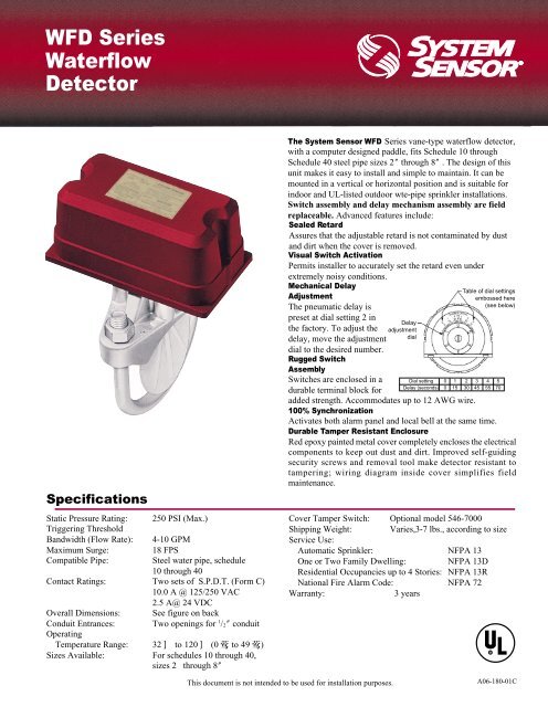
The System Sensor <strong>WFD</strong> <strong>Series</strong> vane-type waterflow detector,<br />
with a computer designed paddle, fits Schedule 10 through<br />
Schedule 40 steel pipe sizes 2 through 8 . The design of this<br />
unit makes it easy to install and simple to maintain. It can be<br />
mounted in a vertical or horizontal position and is suitable for<br />
indoor and UL-listed outdoor wte-pipe sprinkler installations.<br />
Switch assembly and delay mechanism assembly are field<br />
replaceable. Advanced features include:<br />
Sealed Retard<br />
Assures that the adjustable retard is not contaminated by dust<br />
and dirt when the cover is removed.<br />
Visual Switch Activation<br />
Permits installer to accurately set the retard even under<br />
extremely noisy conditions.<br />
Mechanical Delay<br />
Adjustment<br />
The pneumatic delay is<br />
preset at dial setting 2 in<br />
the factory. To adjust the<br />
delay, move the adjustment<br />
dial to the desired number.<br />
Rugged Switch<br />
Assembly<br />
Switches are enclosed in a<br />
durable terminal block for<br />
This document is not intended to be used for installation purposes.<br />
Delay<br />
adjustment<br />
Table of dial settings<br />
embossed here<br />
(see below)<br />
added strength. Accommodates up to 12 AWG wire.<br />
100% Synchronization<br />
Activates both alarm panel and local bell at the same time.<br />
Durable Tamper Resistant Enclosure<br />
Red epoxy painted metal cover completely encloses the electrical<br />
components to keep out dust and dirt. Improved self-guiding<br />
security screws and removal tool make detector resistant to<br />
tampering; wiring diagram inside cover simplifies field<br />
maintenance.<br />
Cover Tamper Switch: Optional model 546-7000<br />
Shipping Weight: Varies,3-7 lbs., according to size<br />
Service Use:<br />
Automatic Sprinkler: NFPA 13<br />
One or Two Family Dwelling: NFPA 13D<br />
Residential Occupancies up to 4 Stories: NFPA 13R<br />
National Fire Alarm Code: NFPA 72<br />
Warranty: 3 years<br />
dial<br />
Dial setting 0 1 2 3 4 5<br />
Delay (seconds) 0 15 30 45 55 70<br />
A06-180-01C
Tamper proof wrench<br />
(P/N <strong>WFD</strong>W)<br />
DELAY ADJUSTMENT:<br />
Factory set @ 30 sec.<br />
To change delay time,<br />
rotate dial either<br />
direction (see diagram<br />
on front page).<br />
Delay mechanism<br />
(Replacement<br />
P/N A3008-00)<br />
Mounting plate<br />
Pipe saddle<br />
Plastic vane<br />
Roll paddle opposite<br />
of flow arrow<br />
while inserting<br />
Saddle gasket<br />
<strong>Waterflow</strong><br />
6.700<br />
Cover<br />
Pipe<br />
<strong>WFD</strong> Assembly Diagram<br />
Engineer Architect Specifications:<strong>WFD</strong> <strong>Waterflow</strong> <strong>Detector</strong>s<br />
Ordering Information<br />
Terminal block<br />
(Replacement P/N A77-01-02)<br />
Ground screw provided<br />
Electrical conduit entrance<br />
(.875 dia.)<br />
U bolt<br />
U bolt nut<br />
<strong>WFD</strong> Size Hole Size<br />
2 -31 /2 1 1 /4<br />
4 -8 2<br />
Vane-type waterflow detectors shall be installed on system piping<br />
as designated on the drawings and/or as specified herein.<br />
<strong>Detector</strong>s shall mount on any clear pipe span of the appropriate<br />
nominal size, either a vertical upflow or horizontal run, at least<br />
6 from any fittings which may change water direction, flow rate,<br />
or pipe diameter or no closer than 24 from a valve or drain.<br />
<strong>Detector</strong>s shall have a sensitivity in the range of 4 to 10 gallons<br />
per minute and a static pressure rating of 250 psi for 2 -8 pipes.<br />
The detector shall respond to waterflow in the specified direction<br />
after a preset time delay which is field adjustable. The delay<br />
<strong>WFD</strong>20 <strong>Waterflow</strong> <strong>Detector</strong>, Schedule 10/40, 2 (50mm)<br />
<strong>WFD</strong>25 <strong>Waterflow</strong> <strong>Detector</strong>, Schedule 10/40, 2 1 /2 (65mm)<br />
<strong>WFD</strong>30 <strong>Waterflow</strong> <strong>Detector</strong>, Schedule 10/40, 3 (80mm)<br />
<strong>WFD</strong>35 <strong>Waterflow</strong> <strong>Detector</strong>, Schedule 10/40, 3 1 /2<br />
<strong>WFD</strong>40 <strong>Waterflow</strong> <strong>Detector</strong>, Schedule 10/40, 4 (100mm)<br />
<strong>WFD</strong>50 <strong>Waterflow</strong> <strong>Detector</strong>, Schedule 10/40, 5<br />
<strong>WFD</strong>60 <strong>Waterflow</strong> <strong>Detector</strong>, Schedule 10/40, 6 (150mm)<br />
<strong>WFD</strong>80 <strong>Waterflow</strong> <strong>Detector</strong>, Schedule 10/40, 8 (200mm)<br />
A3008-00 Replacement Dealy Mechanism for <strong>WFD</strong> 2 -8 sizes<br />
U bolt nut<br />
Pipe saddle<br />
U bolt<br />
3.0”<br />
Switch 1<br />
to nonsilenceable initiating<br />
zone of listed FACP<br />
3.75”<br />
Width: See Table<br />
Strip Gage<br />
to power source<br />
compatible<br />
with bell<br />
Top View<br />
1.6”<br />
Pipe<br />
Plastic vane<br />
Model Width Model Width<br />
<strong>WFD</strong>20 4.6 <strong>WFD</strong>40 6.8<br />
<strong>WFD</strong>25 4.6 <strong>WFD</strong>50 7.8<br />
<strong>WFD</strong>30 5.2 <strong>WFD</strong>60 9.0<br />
<strong>WFD</strong>35 5.7 <strong>WFD</strong>80 10.8<br />
Typical Local Bell Connection<br />
NOTE:Common and B connections will<br />
close when vane is deflected, i. e.,<br />
when water is flowing. Dual switches<br />
permit applications to be combined<br />
on a single detector.<br />
Switch 2<br />
<strong>WFD</strong> <strong>WFD</strong><br />
B B B B<br />
COM COM COM COM<br />
Typical FACP Connection<br />
<strong>WFD</strong> Field wiring Diagram<br />
<strong>WFD</strong><br />
Dimensions<br />
CONTACT RATINGS<br />
125/250 VAC 10AMPS<br />
24 VDC 2.5AMPS<br />
A77-01-02 Replacement Terminal Block for <strong>WFD</strong><br />
546-7000 Cover Tamper Switch Kit for <strong>WFD</strong><br />
S07-66-02 Replacement Tamper Screws for Cover of <strong>WFD</strong><br />
<strong>WFD</strong>W Replaccement Tamper Proof Wrench for Cover of<br />
<strong>WFD</strong><br />
C58-164-01 Replacement Metal Cover<br />
<strong>WFD</strong>N4 NEMA4 Gasket Kit<br />
*ULC version designated with A following the model number and<br />
factory installed with cover tamper switch.<br />
B<br />
COM<br />
local<br />
bell<br />
end-of-line-resistor<br />
mechanism shall be a sealed mechanical pneumatic unit with<br />
visual indication of actuation. The actuation mechanism shall<br />
include a polyethylene vane inserted through a hole in the pipe<br />
and connected by a mechanical linkage to the delay mechanism.<br />
Outputs shall consist of dual SPDT switches (form C contacts).<br />
Two conduit entrances (one of which is a knockout type) for<br />
standard fittings of commonly used electrical conduit shall be<br />
provided on the detectors. A grounding provision is provided. All<br />
detectors shall be listed by Underwriters Laboratories for indoor<br />
or outdoor use.<br />
System Sensor Worldwide Manufacturing & Distribution<br />
System Sensor Headquarters<br />
3825 Ohio Avenue<br />
St. Charles, IL 60174<br />
Ph: 800-SENSOR2<br />
Fx: 630/377-6495<br />
Documents on Demand:<br />
1-800-736-7672 3<br />
Web:www.systemsensor.com<br />
System Sensor - China<br />
28 Tuan Jie South Road, Xi , an National<br />
Hi-tech Industrial Development Zone,<br />
Province of Shaanxi, 710075, CHINA<br />
Ph: ++ 86.29.8832.0119<br />
Sales Ph: ++ 86.29.8833.2810 8833.2827<br />
Fx: ++ 86.29.8832.5110 8833.2959<br />
Web:www.systemsensor.com.cn<br />
E-mail: sales@systemsensor.com.cn<br />
System Sensor - Canada<br />
Ph: ++ 1.905.812.0767<br />
Fx: ++ 1.905.812.0771<br />
System Sensor - Singapore<br />
Ph: ++ 65.273.2230<br />
Fx: ++ 65.273.2610<br />
System Sensor - Australia<br />
Ph: ++ 613.54.281.142<br />
Fx: ++ 613.54.281.172<br />
System Sensor - Far East<br />
Ph: ++ 852.2191.9003<br />
Fx: ++ 852.2736.6580<br />
System Sensor - Europe<br />
Ph: ++ 44.1403.276500<br />
Fx: ++ 44.1403.276501<br />
System Sensor - India<br />
Ph: ++ 91.124.637.1770 Extn 2700<br />
Fx: ++ 91.124.637.3118