EZII Series Technical Manual - Digi-Star
EZII Series Technical Manual - Digi-Star
EZII Series Technical Manual - Digi-Star

Create successful ePaper yourself
Turn your PDF publications into a flip-book with our unique Google optimized e-Paper software.
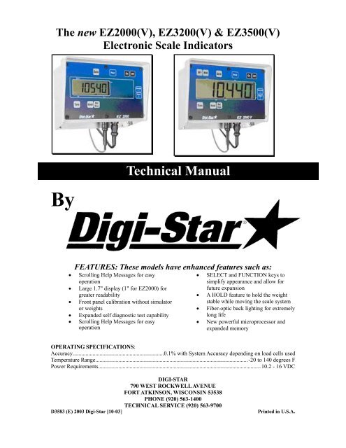
The new EZ2000(V), EZ3200(V) & EZ3500(V)<br />
Electronic Scale Indicators<br />
By<br />
<strong>Technical</strong> <strong>Manual</strong><br />
FEATURES: These models have enhanced features such as:<br />
• Scrolling Help Messages for easy<br />
operation<br />
• Large 1.7" display (1" for EZ2000) for<br />
greater readability<br />
• Front panel calibration without simulator<br />
or weights<br />
• Expanded self diagnostic test capability<br />
• Scrolling Help Messages for easy<br />
operation<br />
• SELECT and FUNCTION keys to<br />
simplify appearance and allow for<br />
future expansion<br />
• A HOLD feature to hold the weight<br />
stable while moving the scale system<br />
• Fiber-optic back lighting for extremely<br />
long life<br />
• New powerful microprocessor and<br />
expanded memory<br />
OPERATING SPECIFICATIONS:<br />
Accuracy................................................................0.1% with System Accuracy depending on load cells used<br />
Temperature Range...........................................................................................................-20 to 140 degrees F<br />
Power Requirements..................................................................................................................10.2 - 16 VDC<br />
DIGI-STAR<br />
790 WEST ROCKWELL AVENUE<br />
FORT ATKINSON, WISCONSIN 53538<br />
PHONE (920) 563-1400<br />
TECHNICAL SERVICE (920) 563-9700<br />
D3583 (E) 2003 <strong>Digi</strong>-<strong>Star</strong> [10-03] Printed in U.S.A.
<strong>EZII</strong> <strong>Series</strong> <strong>Technical</strong> <strong>Manual</strong><br />
Table of Contents<br />
1. Short Form Calibration ..................................................................... 4<br />
2. Long Form Setup Values.................................................................... 8<br />
3. Self Test.............................................................................................. 38<br />
3.1 Initiating the Self Test............................................................................. 38<br />
3.2 Test Sequence........................................................................................... 38<br />
4. Weighing Errors ............................................................................... 40<br />
5. RS-232 Specifications ....................................................................... 41<br />
5.1 Signal Levels............................................................................................ 41<br />
5.2 Communication Parameters .................................................................. 41<br />
5.3 Port Wire Connections ........................................................................... 41<br />
5.4 Computer Command Set........................................................................ 42<br />
5.5 Numeric Entry Commands .................................................................... 42<br />
5.6 Scoreboard Data Format........................................................................ 42<br />
5.7 Print Data Format - Two Line ............................................................... 43<br />
5.8 Print Data Format - One Line ............................................................... 44<br />
5.9 Print Samples .......................................................................................... 45<br />
5.10 Computer Interface Print Samples ....................................................... 46<br />
5.11 CSV Print Format................................................................................... 46<br />
6. DDL Set Up Requirements .............................................................. 50<br />
Appendix A Short Form Calibration ....................................................... 51<br />
Determining the SETUP number ...................................................................... 52<br />
Adjusting the Indicator to Match Another Scale ............................................. 53<br />
Appendix B Weigh Method Descriptions ................................................. 57<br />
Adjustment Options for Weigh Methods #1 and #2......................................... 58<br />
Appendix C Long Form Setup and Calibration ...................................... 61<br />
Appendix D Self Test Error Messages....................................................... 63<br />
Error Descriptions .............................................................................................. 63<br />
Key Locations and Switch Numbers ................................................................. 67<br />
Keypad Failure Error Codes.............................................................................. 67<br />
Initiating Key Test............................................................................................... 68<br />
Terminating the Test ........................................................................................... 68<br />
2
Appendix E - Operating the Mix Counter Feature ................................. 69<br />
Purpose................................................................................................................. 69<br />
Setup and Drive Ratio Determination............................................................... 69<br />
Installing the Proximity Sensor ......................................................................... 71<br />
7. Appendix F Serial Cable Drawings................................................. 72<br />
EZ2000/EZ2000V Operator <strong>Manual</strong>________________ See F3531<br />
EZ3200 Operator <strong>Manual</strong> ________________________ See F3570<br />
Remote RD2000 and RD2000V Displays____________ See F3416<br />
EZ3500 Operator <strong>Manual</strong> ________________________ See D3599<br />
Always keep this manual by your scale indicator.<br />
All rights reserved. Reproduction of any part of this manual in any form whatsoever without <strong>Digi</strong>-<strong>Star</strong>’s express written permission is<br />
forbidden. The contents of this manual are subject to change without notice. All efforts have been made to assure the accuracy of the<br />
contents of this manual. However, should any errors be detected, <strong>Digi</strong>-<strong>Star</strong> would greatly appreciate being informed of them. The<br />
above notwithstanding, <strong>Digi</strong>-<strong>Star</strong> can assume no responsibility for any errors in this manual or their consequence.<br />
3
<strong>Digi</strong>-<strong>Star</strong> <strong>EZII</strong> <strong>Series</strong> Short Form Calibration<br />
<strong>EZII</strong> <strong>Series</strong> <strong>Technical</strong> <strong>Manual</strong><br />
1. Short Form Calibration<br />
Warning!<br />
This indicator was calibrated at the factory to weigh accurately with your system.<br />
Additional calibration is not necessary under normal conditions.<br />
The Short Form Setup & Calibration procedure allows you to change the “SETUP”<br />
and “CAL” numbers of the indicator. You may want to perform this procedure if:<br />
• The indicator is being connected to different load cells, or<br />
• you want to adjust the calibration to match another scale system.<br />
Before continuing, first write down the current SETUP and CAL numbers of your EZ<br />
indicator. These numbers are displayed during the Self Test. To run the self test:<br />
With the indicator already ON, press the key to start the Self Test. Press the<br />
key to "pause" the Self Test while numbers are displayed. Press the key again to<br />
"resume".<br />
SETUP # ________ CAL # ____________<br />
Keep this information for future reference.<br />
Note: Do not attempt to calibrate the scale if the indicator is not reading stable<br />
weights. The calibration procedure will not fix instability, inconsistencies, or flashing<br />
"RANGE" messages.<br />
4
<strong>Digi</strong>-<strong>Star</strong> <strong>EZII</strong> <strong>Series</strong> Short Form Calibration<br />
The Short Form has only two values: SETUP and CAL.<br />
Note: The Short Form Values are NOT displayed in Long Form Setup. See Appendix A:<br />
for additional Short Form information.<br />
To Enter Short Form Setup<br />
Setup Number (SETUP)<br />
1 4 6 0 4 0<br />
W G D C C C<br />
The digits in this number represent four<br />
different items. From left to right:<br />
WGDCCC.<br />
W = Weigh Method<br />
G = Gain<br />
D = Display Count Index (0-9)<br />
CCC = Capacity/1000<br />
5<br />
Press and hold the key and then press the<br />
key.<br />
The word SETUP is displayed briefly. Next, a<br />
number is displayed. The digit on the indicator<br />
farthest to the right flashes. Use the or<br />
key to change which digit is active<br />
(flashing). Use the or key to change<br />
the value of the digit.
<strong>Digi</strong>-<strong>Star</strong> <strong>EZII</strong> <strong>Series</strong> Short Form Calibration<br />
W=Weigh Method This value selects the weigh method or signal<br />
averaging scheme to be used by the scale system<br />
and the Display Unit.<br />
6<br />
Weigh<br />
Method<br />
Settings<br />
Characteristic<br />
1-LB General<br />
2-LB Slow<br />
3-LB Fast<br />
4-LB Lock-On<br />
5-KG General<br />
6-KG Slow<br />
7-KG Fast<br />
8-KG Lock-On<br />
See Appendix B for additional information.<br />
G=Gain Gain. This value selects the amplification to be<br />
used on the loadcell signal. This is applicationspecific<br />
and should only be altered by trained<br />
technicians. This value is NOT accessible in the<br />
Long Form setup.<br />
D=Display Count Index (0-9) This is an index into the following table:<br />
Index Display Count<br />
0 < .2<br />
1 0.2<br />
2 0.5<br />
3 1<br />
4 2<br />
5 5<br />
6 10<br />
7 20<br />
8 50<br />
9 100<br />
These can be selected in the Long Form setup.<br />
CCC=Capacity/1000 This number represents capacity divided by one<br />
thousand.<br />
Press the ON key to advance to the calibration number.
<strong>Digi</strong>-<strong>Star</strong> <strong>EZII</strong> <strong>Series</strong> Short Form Calibration<br />
Calibration Number { CAL }:<br />
This value represents the weight this scale would<br />
display with a loadcell input of .4mV/V.<br />
An example of a Calibration Number could be<br />
"032890".<br />
Press the key to enter the calibration<br />
number.<br />
Note: The system automatically returns to the<br />
normal weighing mode after Calibration Number<br />
is set.<br />
7
<strong>Digi</strong>-<strong>Star</strong> <strong>EZII</strong> <strong>Series</strong> Long Form Setup<br />
2. Long Form Setup Values<br />
The Long Form Setup/Calibration is split into four (4) menus. See Appendix C for a<br />
tabled explanation of each. Menu selections for the entire <strong>EZII</strong> <strong>Series</strong> are listed here.<br />
Optional features in the table below appear in italics. The Setup/Calibration values that<br />
are available depend on the options installed. For example, the setup values Time Format<br />
(TIME F) , Time (TIME), Date Format (DATE F), and Date (DATE) will not be<br />
displayed if the “Clock Option” is not installed.<br />
Menu 1 Menu 2 Menu 3 Menu 4 CALIB<br />
LANGAG<br />
DRATE<br />
MOTION<br />
ZTRACK<br />
W MTHD<br />
LOCKON<br />
TR HLD<br />
SCALID<br />
LKNHLD<br />
TIME F *<br />
TIME *<br />
DATE F *<br />
DATE *<br />
TAREAP<br />
1L PRT<br />
SCOREM<br />
APRINT<br />
COM IN<br />
PRTFMT<br />
MEDIA<br />
C1 DLY<br />
C2 DLY<br />
EST WT �<br />
COUNT<br />
ARANGE<br />
LB-KG<br />
CAP<br />
WM1-A1<br />
WM1-A2<br />
WM1-A3<br />
WM2-A1<br />
WM2-A2<br />
WM2-A3<br />
* Available only if clock option is installed.<br />
� Only option in menu on an EZ2000.<br />
8<br />
P-MTHD/P-ALM<br />
RM INP<br />
AL OUT<br />
BUZZER<br />
PRETAR<br />
TMRCTR<br />
DRATIO<br />
E MTHD<br />
TOLER<br />
DELAY<br />
INGNM<br />
ACCUM<br />
USERID<br />
MSTOR<br />
RESIZE<br />
RECTOT<br />
INGSIZ<br />
SCOOP%<br />
AERROR<br />
TCALB<br />
CAL
<strong>Digi</strong>-<strong>Star</strong> <strong>EZII</strong> <strong>Series</strong> Long Form Setup<br />
To Enter Long Form Setup<br />
To Exit Long Form Setup<br />
9<br />
Press and hold the key and then<br />
press the key.<br />
The following message is displayed:<br />
“PRESS SELECT – MENU 1 –<br />
MENU 2 – MENU 3 –<br />
CALIBRATION – EXIT – THEN<br />
PRESS ON KEY”<br />
Press the key to select which menu<br />
to enter. Press the key to select and<br />
proceed to the next menu item.<br />
To EXIT the Setup/Calibration, press the<br />
key after the message: “PRESS<br />
SELECT – MENU 1 – MENU 2 –<br />
MENU 3 – CALIBRATION –<br />
EXIT – THEN PRESS ON KEY”<br />
is displayed.
<strong>Digi</strong>-<strong>Star</strong> <strong>EZII</strong> <strong>Series</strong> Long Form Setup<br />
Help Messages<br />
Menu 1 Options<br />
LANGAG (Language Setup)<br />
10<br />
At anytime during the Long Form setup,<br />
press the key (or the HELP key on<br />
2000V and EZ3200) for additional<br />
information.<br />
Select the language that will be used to<br />
display Help Messages. Press the<br />
key (on an EZ2000 use the [ZERO] key<br />
to display Help messages) to scroll<br />
through the options. Press the key<br />
to enter selection and proceed to the next<br />
menu item.<br />
Select one of the following:<br />
English ENGLSH<br />
Dutch NEDERL<br />
French FRANCS<br />
German DEUTSH<br />
Italian ITALAN<br />
Portuguese PORT<br />
Spanish ESPANL<br />
Danish DANSK
<strong>Digi</strong>-<strong>Star</strong> <strong>EZII</strong> <strong>Series</strong> Long Form Setup<br />
D RATE (Display Rate Setup)<br />
11<br />
Select the number of times per second to<br />
update the display. This also applies to<br />
remote units if installed.<br />
Select 1, 2, 3, or 4.<br />
Press the key to scroll through<br />
options, press the key to enter<br />
selection and proceed to the next menu<br />
item.<br />
Note: When selecting the Weigh method<br />
(General, Slow, or Fast) or when setting<br />
the Weigh Method Adjustment Options<br />
(see Menu #3 of the Long Form Setup), a<br />
change in Display Rate affects how the<br />
weight appears on the scale. A selection<br />
of ‘1’ update per second helps to stabilize<br />
the weight. A selection of ‘4’ updates per<br />
second provides more response to weight<br />
changes but may cause the weight to<br />
appear “jumpy.” The Display Rate is set<br />
to ‘2’ at the factory.
<strong>Digi</strong>-<strong>Star</strong> <strong>EZII</strong> <strong>Series</strong> Long Form Setup<br />
MOTION (Motion Setup)<br />
ZTRACK (Zero Track Setup)<br />
12<br />
Select On or Off. If set to On, an<br />
annunciator flashes under the word<br />
Motion on the display to indicate unstable<br />
weight.<br />
The MOTION parameter limits operation<br />
if the scale is unstable. It does not correct<br />
for the instability. It is up to the operator<br />
to correct the unstable environment.<br />
The following items are disabled until the<br />
weight is stable:<br />
- Printer output<br />
- Zero/Balance function<br />
- Tare function<br />
- Ingredient Auto-advance<br />
Note: Motion is temporarily turned on<br />
during all system weight calibrations to<br />
insure a stable measurement. It is turned<br />
off after calibration if Off was selected in<br />
Motion setup.<br />
Select On or Off. If set to On, the scale<br />
will adjust for small weight variances.<br />
This allows the scale to compensate for<br />
such things as mud or snow accumulation<br />
on a platform scale. The maximum<br />
instantaneous weight that zero tracking<br />
can remove is approximately 0.05% of<br />
the scales Capacity Limit value or<br />
Max. Weight = .0005 * Capacity Limit<br />
Note: Zero Tracking is temporarily<br />
turned Off during all system weight<br />
calibrations to insure a proper<br />
“ZERO/BALANCE” is obtained. It is<br />
“turned on” after calibration if “ON” was<br />
selected in setup.
<strong>Digi</strong>-<strong>Star</strong> <strong>EZII</strong> <strong>Series</strong> Long Form Setup<br />
W MTHD (Weigh Method Setup)<br />
LOCKON<br />
13<br />
Select the weigh method:<br />
1 – General<br />
2 – Slow<br />
3 – Fast<br />
4 – Lock-On<br />
Note: Setting the Weigh Method in the<br />
“Long Form” DOES NOT affect the<br />
Display Unit LB/KG.<br />
Note: Weigh method adjustments are<br />
available to allow the operator to adjust<br />
the filtering characteristics of Weigh<br />
Methods #1 and #2. These adjustments<br />
change how the scale processes the<br />
weight signal received from the loadcells.<br />
See Weigh Method Adjustment Options<br />
(WM1-A1) in Menu #3 of the Long Form<br />
Setup.<br />
Press the key to scroll through<br />
options. Press the key to enter<br />
selection and proceed to the next menu<br />
item.<br />
See Appendix B for additional<br />
information<br />
Press the key to scroll through<br />
selections 1 thru 9. Press the key to<br />
store setting and proceed to the next<br />
menu item.<br />
Select 1-9.<br />
A low value, such as 1 or 2, allows the<br />
system to be more sensitive to animal<br />
movement. A high value, such as 8 or 9,<br />
will allow the scale to lock on faster. Use<br />
the lowest setting that still allows the<br />
system to lock on consistently.
<strong>Digi</strong>-<strong>Star</strong> <strong>EZII</strong> <strong>Series</strong> Long Form Setup<br />
TR HLD (TR Inventory Hold)<br />
SCALID (Scale ID Setup)<br />
LKNHLD (Lock & Hold)<br />
14<br />
Displays GROSS weight if TR key (on<br />
the handheld transmitter) is held for three<br />
(3) seconds.<br />
Press the key to scroll through<br />
options. Press the key to enter<br />
selection and proceed to the next menu<br />
item.<br />
This feature allows the operator to<br />
identify the scale with a (truck or mixer<br />
number).<br />
After entering the SCALID menu, the<br />
scale’s default name “NEW EZ” will be<br />
displayed on the screen.<br />
Press “CLEAR” several times to clear out<br />
the existing number and enter the desired<br />
scale identification number or letter on<br />
the numeric keypad. Press the key<br />
to store the ID number and advance to the<br />
next menu item.<br />
Press the key to toggle the "Lock<br />
& Hold" feature to "ON".<br />
Place an animal onto the platform. Once<br />
"locked", the weight will be displayed<br />
until another animal (that exceeds 2.5%<br />
of scale capacity) steps on the platform.<br />
The indicator will return to normal<br />
weighing after 5 minutes if no other<br />
animal steps on the weighing platform.<br />
The Recheck key can also be used to<br />
return the indicator to the weighing mode.<br />
Press the key to enter the selection<br />
and advance to the next menu item.
<strong>Digi</strong>-<strong>Star</strong> <strong>EZII</strong> <strong>Series</strong> Long Form Setup<br />
Menu 2 Options<br />
TIME F (Time Format)<br />
TIME<br />
15<br />
Select AM/PM or 24 HR.<br />
Press the key to scroll through<br />
options, press the key to enter<br />
selection and proceed to the next menu<br />
item.<br />
Enter the desired time. Time format is<br />
HH:MM:SS. Press and hold the<br />
key to change the time. The key<br />
only increases digit, keep scrolling until<br />
the desired number is displayed.<br />
Press the key to move from SS to<br />
MM to HH.<br />
Press the key when finished entering<br />
the correct time.<br />
If AM/PM format has been selected for<br />
time format, then AM/PM is displayed.<br />
Note: This is only displayed if the Time<br />
has been changed.<br />
Press the key to select AM or PM<br />
as needed.<br />
Press the key to enter selection and<br />
proceed to the next menu item.
<strong>Digi</strong>-<strong>Star</strong> <strong>EZII</strong> <strong>Series</strong> Long Form Setup<br />
DATE F (Date Format)<br />
16<br />
Select the date format. Press the<br />
key to view the formats available. Select<br />
one of the following:<br />
1 = MM/DD<br />
2 = MM/DD/YY<br />
3 = MM/DD/YYYY<br />
4 = DD/MM<br />
5 = DD/MM/YY<br />
6 = DD/MM/YYYY<br />
7 = DD/MO/YY<br />
8 = DD/MO/YYYY<br />
MM = 2 digit month (ex. January=01)<br />
DD = 2 digit date (ex. 23)<br />
YY = 2 digit year (ex. Year 2000=00)<br />
YYYY = 4 digit year (ex. 2000)<br />
MO= 2 character month (ex. January=JA)<br />
Press the key to enter selection and<br />
advance to the next menu item.
<strong>Digi</strong>-<strong>Star</strong> <strong>EZII</strong> <strong>Series</strong> Long Form Setup<br />
DATE<br />
TAREAP (Tare Auto Print Setup)<br />
17<br />
Enter the date in the format selected in the<br />
DATE F option.<br />
Press the key or the key to<br />
increment the value of the flashing digit<br />
(month, day, or year).<br />
Holding the key or the<br />
[NET/GROSS] key down increments the<br />
digit at a faster rate (similar to setting a<br />
digital alarm clock).<br />
Use the key or the key to<br />
select which value is changed (month,<br />
day, or year).<br />
Press the key to enter selection and<br />
proceed to the next menu item.<br />
Press the key to choose On or Off.<br />
If On, when pressed, the key will<br />
auto print the displayed weight.<br />
Press the key to enter selection and<br />
proceed to the next menu item.
<strong>Digi</strong>-<strong>Star</strong> <strong>EZII</strong> <strong>Series</strong> Long Form Setup<br />
1L PRT (One Line Print)<br />
18<br />
Press the key to choose On or Off.<br />
If On, scale data will be printed on one<br />
line. If Off, scale data will be printed on<br />
multiple lines.<br />
Press the key to enter selection and<br />
proceed to the next menu item.<br />
SCOREM (Scoreboard Mode Setup) Press the key to choose the<br />
scoreboard output mode. This determines<br />
how quickly the remote display is<br />
updated. Choose one of the following:<br />
1 Remote display updates<br />
once per second<br />
2 Remote display updates<br />
twice per second<br />
3 Remote display updates<br />
three times per second<br />
4 Remote display updates on<br />
every conversion<br />
5 Remote display updates at<br />
the display rate<br />
6 Remote display updates<br />
when the display weight<br />
changes<br />
Press the key to enter selection and<br />
proceed to the next menu item.
<strong>Digi</strong>-<strong>Star</strong> <strong>EZII</strong> <strong>Series</strong> Long Form Setup<br />
APRINT (Auto Print Setup)<br />
COM IN (Computer Input Line)<br />
19<br />
Press the key to choose On or Off.<br />
If On, pressing the following keys will<br />
auto print weight values:<br />
TARE, TR, ID, LOAD/UNLOAD,<br />
NET/GROSS, and PRINT<br />
Auto Print prints all transactions. This<br />
feature also works with wireless<br />
transmitters.<br />
Press the key to enter the selection<br />
and proceed to the next menu item.<br />
Indicates what is connected to the<br />
serial/printer port. Both settings will<br />
work when connected to a printer. Press<br />
the key to choose one of the<br />
following:<br />
DWNLD (connect to data downloader)<br />
EZ CMD (connect to computer)<br />
Press the key to enter the selection<br />
and proceed to the next menu item.
<strong>Digi</strong>-<strong>Star</strong> <strong>EZII</strong> <strong>Series</strong> Long Form Setup<br />
PRTFMT (Print Format)<br />
MEDIA (Media Type)<br />
20<br />
This feature allows user to select from the<br />
following list of print formats:<br />
AUTO Standard Print Formats<br />
WTONLY Weight Only<br />
DOWNLD Original Downloader Output<br />
DT+TM CSV Weight, Date & Time<br />
ID+TM CSV Weight, ID, Time<br />
IDWTTM CSV ID, Weight, Time<br />
ANIMAL CSV See Section 5.10<br />
3200-A CSV See Section 5.10<br />
3200-B CSV See Section 5.10<br />
32-TMR See EZ3500 Operator <strong>Manual</strong><br />
Press the key to choose from the<br />
above menu and press the key to<br />
enter the selection and proceed to the next<br />
menu item. See section 5 for detailed output<br />
format.<br />
This menu allows the user to select either<br />
Datakey (DATAKY) or DDL as the data<br />
storage device to be used with the<br />
indicator.<br />
Press the key to choose either<br />
DATAKY or DDL.<br />
Press the key to enter the selection<br />
and proceed to the next menu item.
<strong>Digi</strong>-<strong>Star</strong> <strong>EZII</strong> <strong>Series</strong> Long Form Setup<br />
C1 DLY (Print Delay)<br />
C2 DLY<br />
EST WT (Estimated Gross Weight)<br />
Press ON to continue.<br />
21<br />
Press the key to choose the number<br />
of seconds the printer will delay before<br />
advancing to the next print line. Select<br />
one of the following:<br />
OFF No delay<br />
.10 1/10 of a second<br />
.25 ¼ of a second<br />
.50 ½ a second<br />
.75 ¾ of a second<br />
1 1 second<br />
2 2 seconds<br />
3 3 seconds<br />
4 4 seconds<br />
5 5 seconds<br />
If printer has a buffer, use OFF. If using<br />
the downloader, select .10 or .25 seconds.<br />
The downloader needs a minimum of .10<br />
seconds after each line.<br />
Press the key to enter the selection<br />
and proceed to the next menu item.<br />
Press the key or the key to<br />
increment the value of the flashing digit.<br />
Use the key to add digits to the<br />
number.<br />
Use the EST WT to enter a new GROSS<br />
weight. This feature allows the operator to<br />
adjust the gross weight on the scale.
<strong>Digi</strong>-<strong>Star</strong> <strong>EZII</strong> <strong>Series</strong> Long Form Setup<br />
Menu 3 Options<br />
COUNT (Display Count Setup)<br />
ARANGE (Auto Range Setup)<br />
22<br />
Press the key to indicate the<br />
display count.<br />
Indicator displays count in increments of<br />
0.01, 0.02, 0.05, 0.1, 0.2, 0.5, 1, 2, 5, 10,<br />
20, 50, and 100.<br />
Note: If you set the count too small for<br />
the calibration, the readings will be<br />
unstable and the indicator will not be<br />
accurate.<br />
Press the key to enter selection and<br />
proceed to the next menu item.<br />
Press the key to choose On or Off.<br />
If On, increases display count size for<br />
weights over 300 and again at 600<br />
lbs/kgs.<br />
For example, 0 to 300 lbs. (1 lb.<br />
increment), 30 to 60 lbs. (2 lb.<br />
increment), 60↑ (5 lb. increment)<br />
Press the key to enter selection and<br />
proceed to the next menu item.
<strong>Digi</strong>-<strong>Star</strong> <strong>EZII</strong> <strong>Series</strong> Long Form Setup<br />
LB-KG (Weight Unit Setup)<br />
CAP (Scale Capacity Setup)<br />
23<br />
Press the key to choose to display<br />
weight values in lbs (pounds) or kg<br />
(kilograms).<br />
Press the key to enter selection and<br />
proceed to the next menu item.<br />
Use to set the maximum weight for the<br />
scale. CAP should never exceed sum of<br />
load cell capacities.<br />
Press the key or the key to<br />
increment the value of the flashing digit.<br />
Holding the key, or key, down<br />
increments the digit at a faster rate<br />
(similar to setting a digital alarm clock).<br />
Use the key or the key to<br />
select which value is changed.<br />
Press the key to enter selection and<br />
proceed to the next menu item.
<strong>Digi</strong>-<strong>Star</strong> <strong>EZII</strong> <strong>Series</strong> Long Form Setup<br />
WM1-A1 (Weigh Method Adjustments<br />
for Weigh Method #1 – General)<br />
WM1-A2 (Weigh Method Adjustments<br />
for Weigh Method #1 – General)<br />
24<br />
Press the key to choose a value<br />
from 2 – 100 (factory setting = 10).<br />
This setting is the main “filter” setting for<br />
the weigh method. A small filter number<br />
such as 2 or 4, causes the scale to respond<br />
quickly to weight changes, but may cause<br />
the display to appear “jumpy.” A large<br />
filter number, such as 32 or 64, causes the<br />
scale to be more stable, but the scale is<br />
“slow” to respond to weight changes.<br />
Press the key to enter selection and<br />
proceed to the next menu item.<br />
See Appendix B for more information.<br />
Press the key to choose a value<br />
from 0 – 100 (factory setting = 4).<br />
When this adjustment is set to a value<br />
other than 0, it activates a “Quick<br />
Response” feature. This allows the scale<br />
to quickly respond to large weight<br />
changes.<br />
Press the key to enter selection and<br />
proceed to the next menu item.<br />
See Appendix B for more information.
<strong>Digi</strong>-<strong>Star</strong> <strong>EZII</strong> <strong>Series</strong> Long Form Setup<br />
WM1-A3 (Weigh Method Adjustments<br />
for Weigh Method #1 – General)<br />
25<br />
Press the key to set the “Quick<br />
Response Weight” for Weigh Method #1<br />
(General).<br />
If weight added to the scale is greater<br />
than the amount set here, the “Quick<br />
Response Average Number” setting of<br />
WM1-A2 is used as the filter number.<br />
The default is 10% of the scale’s capacity.<br />
For example, if this value is set to 3000,<br />
the weight must change more than 3000<br />
lbs before Weigh Method #1 will use the<br />
“Quick Response Average Number” set in<br />
WM1-A2. Once close to the actual<br />
weight, Weigh Method #1 uses the filter<br />
number set in WM1-A1.<br />
Press the key to enter selection and<br />
proceed to the next menu item.<br />
See Appendix B for more information.
<strong>Digi</strong>-<strong>Star</strong> <strong>EZII</strong> <strong>Series</strong> Long Form Setup<br />
WM2-A1 (Weigh Method Adjustments<br />
for Weigh Method #1 – Slow)<br />
WM2-A2 (Weigh Method Adjustment<br />
for Weigh Method #2 – Slow)<br />
26<br />
Press the key to choose a value<br />
from 2 – 100 (factory setting = 30).<br />
This adjustment is the “Maximum<br />
Average Number” setting for Weigh<br />
Method #2 (Slow). This number<br />
determines how many of the previous<br />
weight samples to average. A small<br />
average number such as 2 or 4 causes the<br />
scale to respond quickly to weight but<br />
may cause the display to appear “jumpy.”<br />
A large filter number, such as 32 or 64,<br />
causes the scale to be more stable, but the<br />
scale is “slow” to respond to weight<br />
changes.<br />
Press the key to enter selection and<br />
proceed to the next menu item.<br />
See Appendix B for more information.<br />
Press the key to choose a value<br />
from 0 – 100 (factory setting = 10).<br />
This adjustment is the “Quick Response<br />
Average Number” setting for Weigh<br />
Method #2 (Slow). If adjustment 2 is set<br />
to a value other than 0, it activates the<br />
“Quick Response” feature. This allows<br />
the scale to quickly respond to large<br />
weight changes.<br />
Press the key to enter selection and<br />
proceed to the next menu item.<br />
See Appendix B for more information.
<strong>Digi</strong>-<strong>Star</strong> <strong>EZII</strong> <strong>Series</strong> Long Form Setup<br />
WM2-A3 (Weigh Method Adjustment<br />
for Weigh Method #2 – Slow)<br />
Press to continue.<br />
27<br />
Adjustment 3 sets the “Quick Response<br />
Weight” for Weigh Method #2 (Slow).<br />
If weight added to the scale is greater<br />
than this amount, the “Quick Response<br />
Average Number” setting of WM2-A2 is<br />
used as the filter number. The default is<br />
10% of the scale’s capacity. For example,<br />
if this value is set to 3000, the weight<br />
must change more than 3000 lbs before<br />
Weigh Method #2 will use the “Quick<br />
Response Average Number” set in WM2-<br />
A2. Once close to the actual weight,<br />
Weigh Method #2 increases the “Quick<br />
Response Average Number” on each<br />
conversion until the number of averages<br />
equals the Maximum Average Number set<br />
in WM2-A1.<br />
Press the key to enter selection and<br />
proceed to the next menu item.<br />
See Appendix B for more information.
<strong>Digi</strong>-<strong>Star</strong> <strong>EZII</strong> <strong>Series</strong> Long Form Setup<br />
Menu 4 Options<br />
P-MTHD (Pre-Alarm Setup) Press the key to choose either<br />
WEIGHT or PERCENT.<br />
P-ALM (Pre-Alarm Setup)<br />
28<br />
Press the key to enter the selection<br />
and proceed to the next menu item.<br />
This value represents a pre-alarm weight<br />
value (lb, kg or percent). This acts as a<br />
setting point for activating the pre-alarm.<br />
The value can be entered using the<br />
and the key or by using the numeric<br />
keypad.<br />
Setting a pre-alarm weight to zero(0)<br />
disables this feature.<br />
Press the key to enter the selection<br />
and proceed to the next menu item.
<strong>Digi</strong>-<strong>Star</strong> <strong>EZII</strong> <strong>Series</strong> Long Form Setup<br />
RM INP (Remote Input Setup)<br />
AL OUT (Alarm Output)<br />
29<br />
When set to PRESET, the Remote Input<br />
on the power cord (and the input from the<br />
TR option) will re-enter the last preset<br />
value entered. When set to TARE, the<br />
Remote Input performs the TARE<br />
function and “zeroes” the display. If<br />
using “Rotation Counter” (optional on<br />
3200 & 3500), set to “MIXCTR”. This<br />
disables “PRESET’ and ‘TARE”. Feature.<br />
On the EZ3200, the options are the same.<br />
However, if a recipe is loaded, the TARE<br />
function causes the Remote Input to<br />
advance ingredients. If no recipes are<br />
loaded, the Remote Input performs a<br />
TARE.<br />
Press the key to select MIXCTR,<br />
PRESET or TARE.<br />
Press the key to enter the selection<br />
and proceed to the next menu item.<br />
When set to TR, the Alarm Output allows<br />
the alarm capabilities of the preset alarm<br />
to be controlled by the TR keys. The<br />
Front Panel Alarm light and the relay<br />
output is ON (+12V) when a TR<br />
command has been accepted by the scale.<br />
PRESET causes the alarm capabilities to<br />
be controlled by the preset alarm.<br />
Press the key to choose either TR<br />
or PRESET.<br />
Press the key to enter the selection<br />
and proceed to the next menu item.
<strong>Digi</strong>-<strong>Star</strong> <strong>EZII</strong> <strong>Series</strong> Long Form Setup<br />
BUZZER (Buzzer On/Off)<br />
PRETAR (Preload Tare)<br />
RELAY (Alarm Relay On/Off)<br />
30<br />
Press the key to set the buzzer to<br />
On or Off. If On, a buzzer will sound if<br />
alarm conditions occur.<br />
Press the key to enter selection and<br />
proceed to the next menu item.<br />
The PRETAR feature allows the tare<br />
weight of a container to be entered using<br />
the numeric keypad.<br />
Press the key to set the PRETAR<br />
“ON” to enable the preload tare feature.<br />
Press the key to enter selection and<br />
proceed to the next menu item.<br />
This feature allows the operator to enable<br />
or disable the Alarm Output Relay. This<br />
output is the orange wire of the power<br />
cord identified as the +12VDC ALARM.<br />
This output is active whenever the Pre-<br />
Alarm or Preset weight has been loaded.<br />
Press the key to set the RELAY<br />
“ON” to enable the alarm relay.<br />
Press the key to enter selection and<br />
proceed to the next menu item.
<strong>Digi</strong>-<strong>Star</strong> <strong>EZII</strong> <strong>Series</strong> Long Form Setup<br />
TMRCTR (Mix Timer Counter)<br />
DRATIO (Mix Timer Drive Ratio)<br />
E MTHD (Ingredient Entry Method)<br />
31<br />
The Mix Timer feature displays mixer<br />
auger revolutions based on input pulses<br />
from a revolution-sensing device and an<br />
adjustable drive ratio that indicates how<br />
many pulses equal one (1) revolution.<br />
Press the key to select either<br />
“REV” or “TIME”.<br />
Press the key to enter selection and<br />
proceed to the next menu item.<br />
The Drive Ratio is a number that tells the<br />
indicator how many pulses equal 1 mixer<br />
revolution. The drive ratio can be any<br />
number between 0.01 and 999.99.<br />
he value can be entered using the<br />
key and the key or by using the<br />
numeric keypad.<br />
Setting a pre-alarm weight to zero(0)<br />
disables this feature.<br />
Press the key to enter the selection<br />
and proceed to the next menu item.<br />
Select the entry method to use when<br />
programming recipes. Select one of the<br />
following:<br />
1 – Amount per animal<br />
2 – Percent per load<br />
3 – Amount per load<br />
Press the key to select the entry<br />
method.<br />
Press the key to enter selection and<br />
proceed to the next menu item.
<strong>Digi</strong>-<strong>Star</strong> <strong>EZII</strong> <strong>Series</strong> Long Form Setup<br />
TOLER (Ingredient Tolerance)<br />
DELAY (Ingredient Advance Delay)<br />
INGNM (Ingredient Name)<br />
32<br />
Select the amount by percentage that an<br />
ingredient can be under or over-loaded<br />
and still automatically advance. Set this<br />
value to Off to always advance after the<br />
ingredient amount has been reached.<br />
Tolerance settings in percentages<br />
OFF, 0.5, 1, 2, 3, 4, 5, 7, or 10<br />
Press the key to select the desired<br />
tolerance.<br />
Press the key to enter selection and<br />
proceed to the next menu item.<br />
If “DELAY” is not set to “MANUAL” the<br />
indicator is in the “Auto-Advance” mode.<br />
“DELAY” controls the number of seconds<br />
to wait before auto-advancing to the next<br />
ingredient of a recipe. Delay can be set to<br />
MANUAL, 1, 2, 3, 5, 7, 10, 20, 30, or 60.<br />
Press the key to select the desired<br />
setting.<br />
Press the key to enter the selection<br />
and proceed to the next menu item.<br />
When set to “MANUAL”, use the<br />
key or the key is to advance to the<br />
next ingredient.<br />
Attach ingredient names to items in the<br />
ingredient table.<br />
Press the key to toggle the<br />
“Ingredient Name” feature “ON”.<br />
Press the key to enter the selection<br />
and proceed to the next menu item.
<strong>Digi</strong>-<strong>Star</strong> <strong>EZII</strong> <strong>Series</strong> Long Form Setup<br />
ACCUM (Accumulation)<br />
USERID (Force User ID)<br />
MSTORE (Media Storage)<br />
RESIZE (Re-Size Recipe)<br />
33<br />
Enables recipe accumulation.<br />
Set to ON or OFF. If ON, operator MUST<br />
enter User ID before using the scale.<br />
Press the key to toggle the “User<br />
ID” feature “ON”.<br />
Press the key to enter the selection<br />
and proceed to the next menu item.<br />
Set to “QSTART” (Quick <strong>Star</strong>t),<br />
“MANUAL” or “AUTO”<br />
Press the key to select the desired<br />
setting.<br />
Press the key to enter the selection<br />
and proceed to the next menu item.<br />
Use the “QSTART” setting for Datakey<br />
only.<br />
<strong>Manual</strong> mode can be used for Datakey or<br />
DDL.<br />
Auto mode is not recommended for use<br />
with the Datakey.<br />
“RESIZE” allws the user to change the<br />
recipe size by changing the amount to<br />
feed or the number of animals for each<br />
pen.<br />
Press the key to toggle the<br />
“RESIZE” feature “ON”.<br />
Press the key to enter the selection<br />
and proceed to the next menu item.
<strong>Digi</strong>-<strong>Star</strong> <strong>EZII</strong> <strong>Series</strong> Long Form Setup<br />
RECTOT (Recipe Total)<br />
INGSIZ (Ingredient Re-Size)<br />
34<br />
“RECTOT” if turned on, provides 4<br />
methods of correcting the batch size based<br />
on previous batch size errors.<br />
Press the key to toggle the<br />
“RECTOT” feature “ON”.<br />
Press the key to enter the selection<br />
and proceed to the next menu item.<br />
“INGSIZE’ if turned on, changes the<br />
batch size based on the weight of the first<br />
ingredient loaded.<br />
Press the key to toggle the<br />
“INGSIZE” feature “ON”.<br />
Press the key to enter the selection<br />
and proceed to the next menu item.
<strong>Digi</strong>-<strong>Star</strong> <strong>EZII</strong> <strong>Series</strong> Long Form Setup<br />
SCOOP% (Display Scoop Percentage)<br />
AERROR (Auto Error)<br />
Press ON to continue.<br />
35<br />
“SCOOP%” if turned on the displays tells<br />
the operator how much to fill the loader<br />
bucket or how big of a “silage cut” to<br />
make. The scoop weight is entered in the<br />
ingredient table.<br />
Press the key to toggle the<br />
“SCOOP%” feature “ON”.<br />
Press the key to enter the selection<br />
and proceed to the next menu item.<br />
Press the key to set Auto Error to<br />
“ON” or “OFF”. If “ON”, error messages<br />
are displayed to notify operator of system<br />
errors.<br />
See Appendix D for a list of errors and<br />
descriptions of each error.
<strong>Digi</strong>-<strong>Star</strong> <strong>EZII</strong> <strong>Series</strong> Long Form Setup<br />
Calibration Menu Options<br />
T CALB (Temperature Calibration)<br />
Scale calibration can be performed at this time.<br />
Press the key to set temperature<br />
compensation to On or Off.<br />
If On, the scale compensates for changes in<br />
temperature that affect the circuitry in the<br />
indicator.<br />
The scale does not process load cell signals<br />
during TCALB. The CAL annunciator is on<br />
momentarily during TCALB.<br />
For example, if set to On, the indicator<br />
recalibrates often when first turned on.<br />
Recalibration decreases as the indicator warms<br />
up.<br />
36
<strong>Digi</strong>-<strong>Star</strong> <strong>EZII</strong> <strong>Series</strong> Long Form Setup<br />
CAL (Dead Weight Calibration) 1. After the system has been properly zeroed,<br />
place a known weight value (ex., 5000 lb.<br />
test weight) on the scale platform.<br />
37<br />
2. Press the key. If calibration weight is at<br />
least 5% of the scale capacity, the message<br />
“CAL” will be displayed.<br />
3. If the scale capacity is not at least 5%, the<br />
system will not accept the calibration value<br />
and display the message “ADD WT”. Add more<br />
weight to the scale until the 5% capacity<br />
weight has been exceeded.<br />
4. After the 5% capacity weight has been<br />
reached, the indicator displays the message<br />
“CAL”. The weight value estimated to be on<br />
the scale at that time is displayed. The weight<br />
on the scale is estimated based on the<br />
previous calibration value.<br />
5. Correct the weight value by pressing the<br />
key to increment the flashing digit and<br />
the key to select the digit to change.<br />
The scale will not accept the weight entered<br />
if motion is detected (weight is not stable)<br />
and will display the error message “MOTION.”<br />
6. When the display reads the correct weight,<br />
press the key to automatically<br />
determine and store the full scale calibration<br />
value.<br />
The message “GOOD”is displayed for a<br />
successful calibration.<br />
Press and to return to the normal weighing mode after Calibration
<strong>Digi</strong>-<strong>Star</strong> <strong>EZII</strong> <strong>Series</strong> Self Test<br />
3. Self Test<br />
3.1 Initiating the Self Test<br />
After turning the scale on, wait for normal operation to begin then press the ON key. The<br />
Self Test tests all settings and performs an internal system check to ensure that the<br />
indicator is working and set properly.<br />
3.2 Test Sequence<br />
<strong>Star</strong>t of Test Sequence:<br />
Display Setup Value:<br />
Display Calibration Number:<br />
Display Temperature Calibration<br />
Count:<br />
Display LCD Segments:<br />
Display Program ID:<br />
System Test:<br />
The word TEST flashes, then the message<br />
“SETUP” is displayed.<br />
If the Scoreboard option is installed, the message<br />
“TEST” may be displayed during the Self Test on<br />
the scoreboard data line, depending on the<br />
SCOREM selection.<br />
The system displays the Short Form Setup Value<br />
first, then the Short Form Calibration value.<br />
The system then cycles through all display<br />
segments to help the operator identify any faulty<br />
areas.<br />
Displays the current version (revision number) of<br />
the software.<br />
The indicator displays the message “RUNNING<br />
SELF TEST – PLEASE WAIT” while performing<br />
internal system testing.<br />
Self Test cannot be paused or terminated during<br />
this ten (10) second test.<br />
38
<strong>Digi</strong>-<strong>Star</strong> <strong>EZII</strong> <strong>Series</strong> Self Test<br />
Self Test System Errors:<br />
Pausing the Test:<br />
Terminating the Test:<br />
If system errors are discovered during internal<br />
diagnostics, the operator will see an error<br />
message. For example, “ERROR 1 – PRESS<br />
NET/GROSS TO CONTINUE” followed by “***<br />
INDICATOR NEEDS SERVICE *** PRESS<br />
NET/GROSS TO CONTINUE”.<br />
Sending a command using the Computer<br />
Interface causes the system to terminate the error<br />
messages and attempt normal system operation.<br />
39<br />
Press the key during the self test to pause<br />
the sequence. Press the key again to restart<br />
the test.<br />
The self test terminates and continues normal<br />
operation if no errors are detected or if keys<br />
other than are pressed.
<strong>Digi</strong>-<strong>Star</strong> <strong>EZII</strong> <strong>Series</strong> Weighing Errors<br />
4. Weighing Errors<br />
Capacity Limit:<br />
The display shows the message "OVRCAP" if the weight on the scale system exceeds the<br />
capacity limit. The capacity value is entered in SETUP to warn of overloading the scale<br />
system.<br />
Over Range:<br />
The display shows the message "+RANGE" if the weight on the scale system exceeds the<br />
maximum weight measurable by the scale system. The over range value is always the<br />
system’s maximum A/D counts multiplied by the scaling factor. The actual weight at<br />
which over range occurs depends on the calibration, zero, and display count size.<br />
Under Range:<br />
The display shows the message "-RANGE" if the weight on the scale system is less than the<br />
minimum weight measurable by the scale system. The under range value is always the<br />
system’s minimum A/D counts multiplied by the scaling factor. The actual weight at<br />
which under-range occurs will depend on the calibration, zero, and display count size.<br />
Note: The <strong>EZII</strong> <strong>Series</strong> supports –RANGE that is approximately equal to +RANGE in<br />
absolute value.<br />
40
<strong>Digi</strong>-<strong>Star</strong> Model EZ2000 / EZ2000V RS-232 Specifications<br />
5. RS-232 Specifications<br />
5.1 Signal Levels<br />
The Printer, Computer, and Scoreboard are capable of communicating using the EIA<br />
Registered Standard #232 (RS-232). The signal levels move between +8 and -8 Volts.<br />
The Scoreboard also has another communication port that drives 20 milli-Amp devices.<br />
5.2 Communication Parameters<br />
Data is transmitted and received in the asynchronous ASCII format. This communication<br />
format is compatible with most printers, computers, and terminals. The Alternate Port<br />
Configuration is used when the Scoreboard Mode (SCOREM) is set to 4.<br />
Standard Port Configuration Alternate Port Configuration<br />
1200 BAUD 9600 BAUD<br />
1 <strong>Star</strong>t Bit 1 <strong>Star</strong>t Bit<br />
7 Data Bits 7 Data Bits<br />
1 EVEN Parity Bit 1 EVEN Parity Bit<br />
1 Stop Bit 1 Stop Bit<br />
“Handshake lines” are not used and XON/XOFF is not supported.<br />
These parameters are not adjustable in the scale. Equipment interfacing to the scale<br />
must match this configuration.<br />
5.3 Port Wire Connections<br />
All serial communications use the J904 connector on the bottom panel of the scale. See<br />
Appendix E for additional information.<br />
Device Function J904 Pin<br />
To Printer RS-232 out Pin 2<br />
Printer Ground Pin 6<br />
From Computer RS-232 In Pin 3<br />
Computer Ground Pin 5<br />
To Scoreboard RS-232 Out Pin 4<br />
Scoreboard Ground Pin 7<br />
Also on the J904 connector:<br />
Device Function J904 Pin<br />
Scoreboard 20mA Current Loop(+) Pin 1<br />
Scoreboard 20mA Current Pin 8<br />
Loop(-)<br />
41
<strong>Digi</strong>-<strong>Star</strong> Model EZ2000 / EZ2000V RS-232 Specifications<br />
5.4 Computer Command Set<br />
The Computer Interface controls the scale's operation by a remote RS-232 computer.<br />
Most commands acknowledge completion of the command by outputting the appropriate<br />
data stream.<br />
Single Letter commands are always in capital letters (UPPER CASE).<br />
The following Single Letter commands are supported:<br />
B Balance indicator, enter GROSS mode.<br />
C Perform CM (Clear Memory)<br />
G Enter GROSS mode.<br />
H Prints the average weight of the values in the memory feature.<br />
M Perform M+ (Memory Plus)<br />
N Enter NET mode, TARE if necessary.<br />
P Print weight data.<br />
R Perform RM (Recall Memory)<br />
T Perform TARE and enter NET mode.<br />
See Format Example<br />
Format Example - B<br />
B - (ASCII Dec. 66) Zero/Balance command.<br />
5.5 Numeric Entry Commands<br />
Numeric Entry commands do not include capital letters. The letters entered in a numeric<br />
entry are lower case. They are sent with the numbers first (one to six numbers with<br />
values 0-9) followed by a lower case letter.<br />
The following Numeric Entry commands are supported:<br />
t Preload a TARE value 0-999999.<br />
Format Example – 60t<br />
60 - Tare Weight<br />
t-(ASCII Dec. 116) Preload Tare<br />
5.6 Scoreboard Data Format<br />
Data is sent from the scale to the scoreboard at a frequency determined by the Scoreboard<br />
Mode (SCOREM) setting. The weight data is sent in the following format:<br />
ABBBCD<br />
Where:<br />
is the ASCII control code "START OF TEXT"(dec. 2).<br />
is the ASCII control code "Carriage Return" (dec. 13).<br />
A is one of the following:<br />
42
<strong>Digi</strong>-<strong>Star</strong> Model EZ2000 / EZ2000V RS-232 Specifications<br />
• minus sign<br />
• SPACE<br />
• number<br />
B is a number or a SPACE.<br />
C is a number, SPACE, or a minus sign (-) indicating a TR command is active.<br />
D is a number or a minus sign (-) indicating that motion is active.<br />
5.7 Print Data Format - Two Line<br />
Data is sent from the scale to the printer whenever the:<br />
• PRINT key is pressed.<br />
• TR option is used.<br />
• Tare auto-print TAREAP is ON.<br />
• Auto-print APRINT is On.<br />
Date and Time make up the first line and will only be present if the Clock Option is<br />
installed.<br />
The data is sent in the following format (see the DATE F menu option in<br />
Setup/Calibration for other format options):<br />
______dymoyr__hh:mmA<br />
xxxxxxID__yxxxxxLB_GR<br />
Where:<br />
is the ASCII control code "Carriage Return" (dec. 13).<br />
is the ASCII control code "Line Feed" (dec. 10).<br />
_ represents a SPACE.<br />
dymoyr is date (Day, Month, & Year format selected in Long Form “DATE F” setting).<br />
hh:mm is Time (hours:minutes).<br />
A is either A (AM), or P (PM) or a space – format is selected in Long Form<br />
“TIME F” setting.<br />
x is a number (0-9), or a SPACE.<br />
ID labels the Identification Number (I.D.#).<br />
y is a number (0-9), SPACE, or a minus sign (-).<br />
LB is either Pounds (LB), or Kilograms (KG).<br />
43
<strong>Digi</strong>-<strong>Star</strong> Model EZ2000 / EZ2000V RS-232 Specifications<br />
GR labels the weight amount<br />
GR - Gross<br />
NE - Net<br />
TA - Tare<br />
M+ - Memory Plus<br />
RM - Recall Memory<br />
CM - Clear Memory<br />
TP - Tare Point Entered<br />
5.8 Print Data Format - One Line<br />
Data is sent from the scale to the printer whenever the:<br />
• PRINT key is pressed.<br />
• TR option is used.<br />
• Tare auto-print TAREAP is On.<br />
• Auto-print – APRINT is On.<br />
Date and Time make up the last part of the line and are only present if the Clock Option is<br />
installed.<br />
The data is sent in the following format. See the DATE F menu option in<br />
Setup/Calibration for other format options. This format must be used with the<br />
downloader:<br />
xxxxxxID_yxxxxxLB_GR_dymoyr_hh:mmA<br />
Where:<br />
is the ASCII control code "Carriage Return" (dec. 13).<br />
is the ASCII control code "Line Feed" (dec. 10).<br />
_ represents a SPACE.<br />
dymoyr is date (Day, Month,& Year format selected in Long Form “DATE F”<br />
setting).<br />
hh:mm is Time (hours:minutes).<br />
A is either A(AM), or P(PM) or a space, format is selected in Long Form<br />
“TIME F” setting.<br />
x is a number(0-9) or a SPACE.<br />
ID labels the Identification Number (I.D.#).<br />
y is a number(0-9), SPACE, or a minus sign '-'.<br />
LB is either Pounds(LB), or Kilograms(KG).<br />
44
<strong>Digi</strong>-<strong>Star</strong> Model EZ2000 / EZ2000V RS-232 Specifications<br />
GR labels the weight amount.<br />
GR - Gross<br />
NE - Net<br />
TA - Tare<br />
M+ - Memory Plus<br />
RM - Recall Memory<br />
CM - Clear Memory<br />
TP - Tare Point Entered<br />
5.9 Print Samples<br />
Shown below are additional print samples from the "EZ" family of scale indicators.<br />
General Information:<br />
The weight and Identification Numbers can have leading spaces.<br />
The weight information can have a decimal point (100910 or 10091.0).<br />
The ASCII Carriage Return (Dec. 13) is represented as
<strong>Digi</strong>-<strong>Star</strong> Model EZ2000 / EZ2000V RS-232 Specifications<br />
The same Print Data with Identification Number & Clock Options, BUT<br />
with the One Line Print (1L PRT) feature enabled:<br />
1 2 3 4<br />
1234567890123456789012345678901234567890<br />
123456ID 109700LB GR 21JA91 11:22A January 21, 1991) starts at column 22 of line 1.<br />
TIME (11:22A -> 11 hours, 22 minutes AM) starts at column 29 of line 1.<br />
<strong>Digi</strong>-<strong>Star</strong> Model EZ2000 / EZ2000V RS-232 Specifications<br />
- Includes weight, display unit, $' if unit is "locked-on", weight<br />
tag (GR, M+, etc...).<br />
- Ends with a ,.<br />
Print example:<br />
1<br />
123456789012<br />
" 0LB GR"<br />
"DOWNLD" - This format is compatible with the original Downloader. It<br />
duplicates the standard EZ 210 / EZ 150 print output. The print<br />
data is the same even while batching on an EZ3200. It is not the<br />
same as the EZ 320 and therefore does not provide the exact same<br />
information while batching. Use this selection when connected to<br />
a Downloader.<br />
- Includes weight, display unit, $' if unit is "locked-on", weight<br />
tag (GR, M+, etc...) date and time.<br />
- Ends with a ,.<br />
"DT+TM " - This is a simple comma delimted format.<br />
- Includes weight, display unit, $' if unit is "locked-on", weight<br />
tag (GR, M+, etc...) and date.<br />
- Ends with a ,.<br />
Print example:<br />
1 2 3<br />
123456789012345678901234567890<br />
" 0,LB, ,GR,13MR02,11:08"<br />
"ID+TM " - This comma delimted format includes ID, time but not date.<br />
- Includes ID, weight, display unit, $' if unit is "locked-on",<br />
weight tag (GR, M+, etc...) and time.<br />
- Ends with a ,.<br />
Print example:<br />
1 2 3<br />
123456789012345678901234567890<br />
" , 0,LB, ,GR,11:08"<br />
"IDWTTM" - This comma delimted format includes ID, time and date.<br />
- Includes ID, weight, display unit, $' if unit is "locked-on",<br />
weight tag (GR, M+, etc...), date and time.<br />
- Ends with a ,.<br />
Print example:<br />
1 2 3 4<br />
1234567890123456789012345678901234567890<br />
"FARM-1, 16090,LB, ,GR,27JA00,10:37P"<br />
47
<strong>Digi</strong>-<strong>Star</strong> <strong>EZII</strong> <strong>Series</strong> RS-232 Specifications<br />
"ANIMAL" - This comma delimted format includes information for animal<br />
weighing.<br />
- Includes $' if unit is "locked-on",weight, weight tag (GR, M+,<br />
etc...), display unit, Memory Weight (RM), Average Count<br />
(Number of times M+ key was pressed), Average Weight, Gross<br />
weight on scale, ID, date and time.<br />
- Ends with a ,.<br />
Print example:<br />
1 2 3 4<br />
5 6 7<br />
12345678901234567890123456789012345678901234567890123456789<br />
01234567890<br />
" , 1400,GR,LB, 2180, 4, 545,<br />
1400, ,11:09,13MR02"<br />
"3200-A" - This comma delimted format includes information for batching<br />
weighing.<br />
- Includes Preset, Weight, Gross Weight, ID, Ingred/Pen Name,<br />
Recipe#, Batch#, Total Rotation Count, display unit, $' if unit is<br />
"locked-on", weight tag (GR, M+, etc...), time and date.<br />
- Ends with a ,.<br />
Print example:<br />
1 2 3 4<br />
5 6 7<br />
12345678901234567890123456789012345678901234567890123456789<br />
01234567890<br />
" 1000, 0, 16100, ,CORN-1, 2,<br />
2, , 9:35P,27JA00"<br />
48
<strong>Digi</strong>-<strong>Star</strong> <strong>EZII</strong> <strong>Series</strong> RS-232 Specifications<br />
"3200-B" - This comma delimted format includes more information for<br />
batching weighing.<br />
- Includes <strong>Manual</strong> Advance indicator, Scale ID, Preset, Weight,<br />
weight tag (GR, M+, etc...), Gross Weight, display unit, $' if<br />
unit is "locked-on", ID, Ingred/Pen Name, Recipe#, Batch#,<br />
Total Rotation Count, Time, Date and User ID.<br />
- Ends with a ,.<br />
Print example:<br />
1 2 3 4 5 6<br />
7 8 9<br />
12345678901234567890123456789012345678901234567890123456789012345<br />
6789012345678901234567890123<br />
"*,NEW EZ, 1000, 0,NE, 16090,LB, , ,CORN-1, 2,<br />
3, , 9:36P,27JA00, "<br />
"32-TMR" - PRELIMINARY! This print format is compatible with the EZ 3500<br />
and allows TMR Tracker & Tracker Lite to store data and create<br />
reports. Please Note: TMR Tracker & Tracker Lite CANNOT send<br />
recipes to the EZ 3200. This feature is included on the EZ 3500.<br />
- <strong>Star</strong>ts with specific control codes for TMR Tracker.<br />
- Includes Scale ID, Line Status, Line Type, Batch#, ID# or<br />
Ingred/Pen name, Recipe#, Preset, Weight, User ID, Time and<br />
TMR Style Date.<br />
- Ends with specific control codes for TMR Tracker.<br />
49
<strong>Digi</strong>-<strong>Star</strong> <strong>EZII</strong> <strong>Series</strong> DDL Set Up Requirements<br />
6. DDL Set Up Requirements<br />
Use of the DDL (Data Downloader) with the <strong>EZII</strong> series indicator requires the latest<br />
software version. It is recommended that you call the <strong>Digi</strong>-<strong>Star</strong> Service Department for<br />
the latest software version and upgrade, if necessary, to become current, before attaching<br />
and using a DDL.<br />
Menu 2 in the long form set up contains some features that must be set for the DDL to<br />
function properly. They are:<br />
SCOREM 0<br />
COM IN DOWNLD<br />
C1 DLY .10<br />
50
<strong>Digi</strong>-<strong>Star</strong> <strong>EZII</strong> <strong>Series</strong> Appendix A Short Form Calibration<br />
Appendix A Short Form Calibration<br />
CALIBRATION<br />
Warning!<br />
This indicator was calibrated at the factory<br />
to weigh accurately with your system.<br />
Additional calibration is not necessary<br />
under normal conditions.<br />
The Short Form Setup & Calibration<br />
procedure (page 55) allows you to change<br />
the “SETUP” and “CAL” numbers of the<br />
indicator. You may want to perform this<br />
procedure if:<br />
• The indicator is being connected to<br />
different load cells, or<br />
• you want to adjust the calibration to<br />
match another scale system.<br />
Before continuing, first write down the<br />
current SETUP and CAL numbers of your<br />
EZ indicator. These numbers are displayed<br />
during the Self Test. To run the self test:<br />
With the indicator already ON, press the<br />
key to start the Self Test. Press the<br />
key to "pause" the Self Test while<br />
numbers are displayed. Press the key<br />
again to "resume".<br />
SETUP # ________ CAL # ____________<br />
Keep this information for future reference.<br />
Note: Do not attempt to calibrate the scale<br />
if the indicator is not reading stable<br />
weights. The calibration procedure will not<br />
fix instability, inconsistencies, or flashing<br />
"RANGE" messages.<br />
51
<strong>Digi</strong>-<strong>Star</strong> <strong>EZII</strong> <strong>Series</strong> Appendix A Short Form Calibration<br />
Press and hold the ZERO key and then press the ON key at the same time.<br />
Determining the SETUP number<br />
Weigh Method<br />
Lb 1 2 3 4<br />
Kg 5 6 7 8<br />
General Slow Fast Lock-On<br />
Gain (1-9)<br />
OLD<br />
Max<br />
Signal<br />
(mV/V)<br />
NEW<br />
Max<br />
Signal<br />
(mV/V)<br />
OLD<br />
Max<br />
Signal<br />
(mV/V)<br />
NEW<br />
Max<br />
Signal<br />
(mV/V)<br />
1 3.0 3.0 6 3.0 3.0<br />
2 1.5 1.5 7 1.5 1.5<br />
3 .75 1.5 8 .75 1.5<br />
4 .75 .75 9 .38 .75<br />
5 .38 .38<br />
Note: OLD gain settings are for PROG ID – <strong>EZII</strong> 0A, <strong>EZII</strong> 0B, and<br />
<strong>EZII</strong> 0C. NEW settings are available for PROG ID <strong>EZII</strong> 1.0 and higher.<br />
Display Count (0-9)<br />
Setting on Indicator Count Size<br />
0 Represents .01, .02, .05 or .1<br />
Select in Long Form Only<br />
1 .2<br />
2 .5<br />
3 1<br />
4 2<br />
5 5<br />
6 10<br />
7 20<br />
8 50<br />
9 100<br />
Press the key for next menu option in Short Form Setup (CAL).<br />
Calibration Number (Calibration Weight at 0.4<br />
mV/V)<br />
52<br />
Capacity/1000
<strong>Digi</strong>-<strong>Star</strong> <strong>EZII</strong> <strong>Series</strong> Appendix A Short Form Calibration<br />
Adjusting the Indicator to Match Another Scale<br />
Sometimes two different scales are used to weigh the same load. When this is done, the<br />
weight measured by each scale may not be the same. This can be caused by one or both<br />
of the scales being slightly out of calibration. This indicator has the ability to match any<br />
other scale, even if that scale is un-calibrated.<br />
To match your EZ scale (Scale A) to another scale (Scale B) you must determine the<br />
Calibration Multiplier. To do this, place a load on Scale A (feed wagon, etc...) and write<br />
down the weight displayed. Repeat several times to determine the average weight. Next,<br />
place the same load on Scale B and again write down the weight displayed. Repeat<br />
several times to determine the average weight.<br />
Use the following formula to determine the Calibration Multiplier for the EZ’s "CAL"<br />
number:<br />
It is important to use an average of several weights before calibrating the scale.<br />
Scale Matching Example<br />
Original<br />
SETUP # 127060<br />
53<br />
Scale Information sheet<br />
Original<br />
SETUP #<br />
_______________________<br />
CAL# 23980 CAL#<br />
_______________________<br />
1 trial 2 trial 3 trial 1 trial 2 trial 3 trial<br />
Scale B 30,000 30,580 28,000 Scale A<br />
Scale B<br />
Scale A 29,440 29,800 27,500 + + =<br />
x<br />
B ÷ A<br />
1.020 + 1.026 + 1.018 = 3.064<br />
B ÷ A 3.064 ÷ 3 trials = 1.021 Cal<br />
Multiplier<br />
x ÷ 3 trials = Cal. Multiplier<br />
New EZCAL# = Orig. EZCAL# × Cal.Multiplier New EZ CAL# = Orig. EZ CAL# x Cal. Multiplier<br />
24484 = 23980 × 1.021<br />
__________ = ____________ x ____________<br />
You should not modify your "SETUP" number. Only your "CAL" number. Follow the<br />
instructions: To Change the Setup/Calibration Numbers.
<strong>Digi</strong>-<strong>Star</strong> <strong>EZII</strong> <strong>Series</strong> Appendix A Short Form Calibration<br />
Connecting EZ Indicator to Other<br />
Load Cells<br />
54<br />
You will need the number and type of loadcells<br />
used in the new scale system. You will also<br />
need the current "SETUP" and "CAL" as<br />
described above. Once you have written down<br />
this information, contact the nearest Scale<br />
Service Center for new "SETUP" and "CAL"<br />
numbers.<br />
Follow the instructions “To Change the Setup /<br />
Calibration Numbers”.
<strong>Digi</strong>-<strong>Star</strong> <strong>EZII</strong> <strong>Series</strong> Appendix A Short Form Calibration<br />
To Change The Setup &<br />
Calibration Numbers<br />
55<br />
Press and hold the key, then press the<br />
key, to enter Short Form Setup & Calibration.<br />
The first message displayed is SETUP.<br />
Next, the actual SETUP number is displayed.<br />
Note: Press the key for additional help<br />
information during Setup and Calibration.<br />
If the correct SETUP number is displayed, press<br />
the key to advance to the CAL number.<br />
1. Press the key to cause the “flashing”<br />
digit to count upward.<br />
2. Press the<br />
flashing.<br />
key to select which digit is<br />
When the correct SETUP number is displayed,<br />
press the key to advance to the CAL<br />
number. This displays the CAL message,<br />
followed by the CAL number.<br />
Note: The CAL number is not a weight. It is a<br />
reference value the indicator uses to determine<br />
the weight. This number directly affects the<br />
accuracy of the scale system.<br />
Change the CAL number using the same method<br />
described in Steps 1& 2. When the display<br />
shows the correct number, press the key.<br />
This causes the number to be stored<br />
permanently in the indicator and returns the<br />
indicator to the weighing mode.
<strong>Digi</strong>-<strong>Star</strong> <strong>EZII</strong> <strong>Series</strong> Appendix A Short Form Calibration<br />
To Return To Weigh Mode<br />
56<br />
To exit setup without changing the displayed<br />
value, press and hold the key, then press<br />
the key.
<strong>Digi</strong>-<strong>Star</strong> <strong>EZII</strong> <strong>Series</strong> Appendix B Weigh Method Descriptions<br />
Appendix B Weigh Method Descriptions<br />
Different electronic techniques or “Weigh Methods” are used in an attempt to better fit<br />
the weighing application. The EZ Scale Indicators provide three (4) different methods:<br />
Setting Characteristic<br />
1 General<br />
2 Slow<br />
3 Fast<br />
4 Lock-On<br />
Weigh methods 1, 2, & 3 are suitable for weighing dead weights and weigh method 4 is<br />
for weighing live animals.<br />
General - Weigh Method #1<br />
The General weigh method is the all-purpose weigh method. It is used for most<br />
applications. General is similar to the weigh method used on Models 5, 10, 15, & 20. A<br />
comparison would be a Model 10 with a TC (Time Constant) of 4.<br />
Slow - Weigh Method #2<br />
The Slow weigh method attempts to provide higher accuracy by filtering many weight<br />
samples over a longer period of time. Small, instantaneous weight changes have less<br />
effect on the displayed weight using this technique.<br />
Fast - Weigh Method #3<br />
The Fast weigh method is more sensitive to weight changes than the other weigh<br />
methods. When a weight changes quickly, the Fast method tries to determine the new<br />
weight as quickly as possible. This is done by providing less filtering during the actual<br />
"weight change." When the weight begins to stabilize, filtering is increased to provide an<br />
accurate weight display.<br />
Lock On - Weigh Method #4<br />
The Lock On weigh method allows scale to weigh active animals and display an accurate<br />
weight that does not fluctuate.. Lock-On sensitivity can be adjusted using the<br />
“LOCKON” menu.<br />
Once the actual weight is displayed, the scale “Locks-On” to the displayed. Weight does<br />
not change, even if the motion never stops. A small ‘L’ appears on the left side of the<br />
display indicating the weight is “Locked-On.” The animal’s weight must be greater than<br />
2.5% of the scales “capacity” weight before the system can “Lock-On.”<br />
In order to break the lock, 50% of the displayed weight must be either added or removed<br />
from the scale. The “Locked-On” weight can be “rechecked” by pressing the [ZERO]<br />
key on the front panel. This breaks the “lock” and the scale recalculates the weight.<br />
Note: In Weigh Method #1, #2 and #3 the ZTRACK (zero-tracking) removes up to 0.05%<br />
of the scale capacity (as shown in setup). In Weigh Method #4 the weight that can be<br />
removed is set to 5lbs(2.2kg).<br />
57
<strong>Digi</strong>-<strong>Star</strong> <strong>EZII</strong> <strong>Series</strong> Appendix B Weigh Method Descriptions<br />
Adjustment Options for Weigh Methods #1 and #2<br />
Adjustment options in Menu #3 of the Long Form Setup allow the operator to adjust the<br />
fintering characteristics of Weigh Methods #1 (General) and #2 (Slow). These<br />
adjustments change how the scale processes the weight signal received from the load<br />
cells. The scale samples a new weight signal 10 times per second, which is every 100<br />
milli-seconds.<br />
The Weigh Method adjustment options are set in Menu #3 of the Long Form Setup.<br />
Weigh Method options (W MTHD) are selected in Menu #1 of the Long Form Setup.<br />
Changing the Display Rate also effects how the weight appears on the scale. A selection<br />
of '1' update per second helps to stabilize the weight. A selection of '4' updates per second<br />
provides more response to weight changes, but may cause the weight to appear "jumpy".<br />
The Display Rate is set to 2 at the factory. The Display Rate adjustment is set in Menu #1<br />
of the Long Form setup.<br />
Weigh Method #1 - General, has three adjustments found in Menu #3.<br />
Weigh Method #1 - Adjustment 1("WM1-A1") can be set from 2 - 100 (factory setting =<br />
10).<br />
Adjustment 1 is the main "filter" setting for the weigh method. A small filter<br />
number like 2 or 4 causes the scale to respond quickly to weight changes, but may<br />
cause the display to appear "jumpy". A large filter number like 32 or 64 causes<br />
the scale to be more stable, but is "slow" to respond to weight changes.<br />
Weigh Method #1 - Adjustment 2("WM1-A2") can be set from 0 - 100 (factory setting =<br />
4).<br />
When Adjustment 2 is set to a value other than 0 it activates a "Quick Response"<br />
feature. This allows the scale to quickly respond to large weight changes. When<br />
the weight changes, the scale first determines how much change has occurred<br />
before it processes the weight.<br />
Weight changes less than the weight value entered in WM1-A3 (see below) will<br />
use the filter number set in WM1-A1 to determine the displayed weight.<br />
Weight changes greater than the weight value entered in WM1-A3 will use the<br />
"Quick Response" filter number set in WMA1-2 until the displayed weight gets<br />
close to the actual weight. Once close to the actual weight, Weigh Method #1 uses<br />
the filter number set in WM1-A1.<br />
In WM1-A2, a small filter number like 2 or 4 will cause the scale to respond<br />
quickly to large weight changes. A large filter number like 32 or 64 will cause the<br />
scale to be more stable and less responsive to weight changes greater than the<br />
amount set in WM1-A3.<br />
58
<strong>Digi</strong>-<strong>Star</strong> <strong>EZII</strong> <strong>Series</strong> Appendix B Weigh Method Descriptions<br />
Weigh Method #1 - Adjustment 3("WM1-A3"):<br />
Adjustment 3 sets the "Quick Response Weight" for Weigh Method #1. If the<br />
weight added to the scale is greater than this amount, the "Quick Response<br />
Average Number" setting of WM1-A2 is used as the filter number. The default is<br />
10% of the scale’s capacity. For example, if this value is set to 3000, than the<br />
weight must change more than 3000 lbs before Weigh Method #1 will use the<br />
"Quick Response Average Number" set in WM1-A2. Once close to the actual<br />
weight, Weigh Method #1 uses the filter number set in WM1-A1.<br />
Weigh Method #2 - Slow, has three adjustments:<br />
Weigh Method #2 - Adjustment 1("WM2-A1") can be set from 2 - 100 (factory setting =<br />
30) :<br />
Adjustment 1 is the "Maximum Average Number" setting for the weigh method.<br />
This number determines how many of the previous weight samples to average. A<br />
small average number like 2 or 4 causes the scale to respond quickly to weight<br />
changes, but may cause the display to appear as "jumpy". A large average number<br />
like 32 or 64 causes the scale to be more stable, but is "slow" to respond to weight<br />
changes.<br />
Weigh Method #2 - Adjustment 2("WM2-A2") can be set from 0 - 100 (factory setting =<br />
10) :<br />
Adjustment 2 is the "Quick Response Average Number" setting for the weigh<br />
method. If Adjustment 2 is set to a value other than 0 it activates the "Quick<br />
Response" feature. This allows the scale to quickly respond to large weight<br />
changes. When the weight changes, the scale first determines how much change<br />
has occurred before it processes the weight.<br />
Weight changes less than the weight value set in WM2-A3 cause the scale to use<br />
the filter number set in WM2-A1 to determine the displayed weight.<br />
Weight changes greater than the weight set in WM2-A3 cause the scale to use the<br />
"Quick Response Average Number" set in WM2-A2 until the displayed weight<br />
gets close to the actual weight. Once close to the actual weight, Weigh Method #2<br />
increases the Quick Response Average Number on each conversion until the<br />
number of averages equals the Maximum Average Number set in WM2-A1.<br />
In WM2-A2, a small number like 2 or 4 will cause the scale to respond quickly to<br />
weight changes greater than the amount set in WM2-A3. A large filter number<br />
like 32 or 64 will cause the scale to be more stable and less responsive to weight<br />
changes greater than the amount set in WM2-A3.<br />
59
<strong>Digi</strong>-<strong>Star</strong> <strong>EZII</strong> <strong>Series</strong> Appendix B Weigh Method Descriptions<br />
Weigh Method #2 - Adjustment 3("WM2-A3"):<br />
Adjustment 3 sets the "Quick Response Weight" for Weigh Method #2. If the<br />
weight added to the scale is greater than this amount, the "Quick Response<br />
Average Number" setting of WM2-A2 is used as the filter number. The default is<br />
10% of the scale’s capacity. For example, if this value is set to 3000, than the<br />
weight must change more than 3000 lbs before Weigh Method #2 will use the<br />
"Quick Response Average Number" set in WM2-A2. Once close to the actual<br />
weight, Weigh Method #2 increases the Quick Response Average Number on each<br />
conversion until the number of averages equals the Maximum Average Number<br />
set in WM2-A1.<br />
60
<strong>Digi</strong>-<strong>Star</strong> <strong>EZII</strong> <strong>Series</strong> 21. Appendix C Long Form Setup<br />
Appendix C Long Form Setup and Calibration<br />
Press and hold the key and then press the key at the same time. Wait until<br />
indicator beeps. To exit the Long Form Setup, press the key and the key at the<br />
same time. The following is a list of parameters (settings to change) available in the<br />
Long Form Setup. See Long Form Setup for a detailed explanation of each parameter<br />
structure for access.<br />
Please note: Settings will only be displayed if their feature is found in the indicator model.<br />
Menu 1 - Basic features in all scales<br />
LANGUAGE {LANGAG} 101 Select Language to be displayed.<br />
DISPLAY RATE {D RATE} 102 Update Display 1, 2, 3, or 4 Times per Second.<br />
MOTION {MOTION} 103 If ON - motion arrow flashes for unstable weight.<br />
ZERO TRACK {ZTRACK} 104 If ON – Zero Track adjusts zero/balance for build up of snow<br />
and mud.<br />
WEIGH METHOD {W MTHD} 105 Select weigh method 1-General 2-Slow 3-Fast 4-Lock-On<br />
LOCK ON {LOCKON} 106 Decrease number if lock-on does not repeat - increase number<br />
to lock-on faster.<br />
TR HOLD {TR HLD} 107 Display gross weight if TR key is held for 3 seconds.<br />
SCALE ID SETUP {SCALID} 108 Allow Operator to identify the scale location (Truck ID or Mixer<br />
Number).<br />
LOCK-N-HOLD {LKNHLD} 109 If ON-lock weight is held until next animal is weighed.<br />
AUTO-OFF {AUTOFF} 111 Indicator turns off after selected minutes of stable weight.<br />
Menu 2 - Clock, Printer & Estimated Weight Features<br />
Clock features<br />
TIME FORMAT {TIME F} 201 Select time format - AM/PM or 24 hour<br />
TIME {TIME} 202 Press and hold Select key to change time - Function key<br />
choses hh:mm:ss.<br />
DATE FORMAT {DATE F} 203 Select date format 1-mm-dd 2-mm/dd/yy 3-mm/dd/yyyy 4-ddmm<br />
5-dd/mm/yy 6-dd/mm/yyyy 7-ddmoyy 8-ddmoyyyy.<br />
DATE {DATE} 204 Press and hold Select key to change date - Function key<br />
choses mm/dd/yy<br />
Print features<br />
TARE AUTO PRINT {TAREAP} 211 If ON - tare will auto-print displayed weight.<br />
ONE LINE PRINT {1L PRT} 212 If ON - scale data will be printed on one line.<br />
SCOREBOARD MODE {SCOREM} 213 Select scoreboard output mode 1-1/sec 2-2/sec 3-3/sec 4every<br />
conversion 5-display rate 6-display weight change.<br />
AUTO PRINT {APRINT} 214 If ON - pressing keys will auto-print weight values.<br />
COMPUTER IN MODE {COM IN} 215 Select computer input mode DOWNLD = data down loader<br />
EZ CMD = ez computer commands.<br />
PRINT WEIGHT ONLY {WTONLY} 216 If ON - Scale only prints weight value.<br />
PRINT FORMAT {prtfmt} 216 Select alternate and comma (CSV) formats - auto is standard<br />
format.<br />
MEDIA TYPE {MEDIA} 217 Select DDL or Datakey for data storage.<br />
COM 1 DELAY {C1 DLY} 221 Select seconds to delay before advancing to next line (was<br />
PRT DLY).<br />
COM 2 DELAY {C2 DLY} 222 Select seconds to delay before advancing to next line.<br />
ESTIMATE WEIGHT {EST WT} 299 Allows operator to adjust Gross weight of scale by changing<br />
the zero/balance.<br />
Menu 3 - Scale Calibration Settings<br />
DISPLAY COUNT { COUNT} 301 Select display count size of weigh values.<br />
61
<strong>Digi</strong>-<strong>Star</strong> <strong>EZII</strong> <strong>Series</strong> 21. Appendix C Long Form Setup<br />
AUTO RANGE {ARANGE} 302 If ON - display count automatically adjusts the count value by<br />
addition of 1 display count at 300 lbs/kgs and 1 display count<br />
at 600 lbs/kgs.<br />
DISPLAY UNIT {LB-KG} 303 Display pounds - lb or kilograms - kg<br />
CAPACITY {CAP} 304 Enter MAXIMUM weight measurable on scale.<br />
WM1 ADJUST 1 {WMA1-1} 305 Increase this number to smoothen weighing<br />
WM1 ADJUST 2 {WMA1-2} 306 Enter a value less than WMA1-1 for quick weight response,<br />
0=OFF.<br />
WM1 ADJUST 3 {WMA1-3} 307 Enter the weight to activate quick weight response.<br />
WM2 ADJUST 1 {WMA2-1} 311 Increase this number to smoothen weighing<br />
WM2 ADJUST 2 {WMA2-2} 312 Enter a value less than WMA2-1 for quick weight response,<br />
0=OFF.<br />
WM2 ADJUST 3 {WMA2-3} 313 Enter the weight to activate quick weight response.<br />
Menu 4 - Batching Features<br />
Preset features<br />
PRE ALARM {P-ALM} 401 Early warning that scale is reaching the preset. Pre-alarm<br />
value can be calculated by weight or percentage.<br />
REMOTE INPUT {RM INP} 402 Set function of remote input line on the power cord.<br />
ALARM OUTPUT {AL OUT} 403 Select Preset OR TR to control Relay, Horn & Lamp.<br />
BUZZER {BUZZER} 404 ALARM BUZZER - Allows user to turn OFF Alarm Horn.<br />
PRELOAD TARE {PRETAR} 405 If ON - tare weights can be entered using the numeric keypad<br />
PRESET AUTO CLEAR {PRECLR} 406 If ON - disables preset after 45 minutes if weight does not<br />
change.<br />
Mix Timer / Rotation Counter features<br />
TIMER/COUNTER {TMRCTR} 421 Select time or mixer revolutions to decrement mix<br />
timer/counter.<br />
DRIVE RATIO {DRATIO} 422 Enter the number of input pulses that equal 1 mixer revolution.<br />
Batching features<br />
ENTRY METHOD {E MTHD} 441 Select batching entry method 1-amount/animal 2percent/load<br />
3-amount/load.<br />
TOLERANCE {TOLER} 442 Select tolerance weight percentage to accept ingredient.<br />
INGR.ADVANCE DELAY {DELAY} 443 Select seconds to delay before advancing to next ingredient.<br />
INGREDIENT NAMES {INGRNM} 444 If ON - displays ingredient names while batching.<br />
ACCUMULATION {ACCUM} 445 If ON - ingredient weights are accumulated while batching.<br />
FORCE USER ID {USERID} 446 If ON - operator MUST enter User ID to use scale.<br />
MEDIA STORAGE {mstore} 447 Select MANUAL, AUTO or QUICK START method for<br />
transferring recipe information with the DDL or Datakey..<br />
RESIZE 3500 RECIPE {resize} 448 If ON - operator can change EZ3500 recipe size.<br />
INGREDIENT RESIZING {INGSIZ} 449 Selects automatic ingredient re-sizing mode.<br />
RECIPE TOTAL {RECTOT} 451 Selects total amount to be displayed when starting recipe.<br />
DISPLAY SCOOP% {SCOOP%} 452 If ON – Displays scoop percentage to load.<br />
TOLERANCE LOCK {overlk} 453 If ON – Prevents auto-advancing if amount exceeds tolerance.<br />
Auto-Error Detection feature.<br />
AUTO ERROR {AERROR} 499 If ON - notifies operator of system errors.<br />
CALIB - CALIBRATION.<br />
TEMP CALIBRATION {T CALB} 801 If ON - scale adjust for temperature changes.<br />
DEAD WEIGHT CAL {CAL} 802 Calibration method using weights.<br />
SHORT FORM - CALIBRATION SETTINGS.<br />
SETUP NUMBER {SETUP} 871 Quick entry value to select weigh method (1-4 lb) (5-8 kg), gain<br />
(1-9), display counts (0-9), and capacity (*1000)<br />
CALIBRATION NUMBER {CAL} 872 Weight that would be displayed at 0.4mV/V for these loadcells.<br />
62
<strong>Digi</strong>-<strong>Star</strong> <strong>EZII</strong> <strong>Series</strong> Appendix D Self Test Error Messages<br />
Appendix D Self Test Error Messages<br />
If system errors are discovered during the Self Test, the following error message is<br />
displayed:<br />
1. “ERROR N Press NET/GROSS to Continue”<br />
(Where N = an error number, see list below.)<br />
2. After pressing the key, the next message displayed is “***INDICATOR<br />
NEEDS SERVICE***PRESS NET/GROSS TO CONTINUE.”<br />
Please note the following:<br />
• If the Scoreboard option is installed and the Scoreboard mode is set to #5 or #6 ,<br />
the scale sends the message “TEST” on the scoreboard data line.<br />
• Sending a command using the Computer Interface causes the system to skip the<br />
error messages and attempt normal system operation.<br />
• The test cannot be terminated while the “RUNNING SELF TEST – PLEASE WAIT”<br />
message is displayed.<br />
Error Descriptions<br />
Please note that broken circuit board solder joints or opens to the IC sockets can also<br />
cause these errors.<br />
Error 1: EPROM FAILURE – Replace I.C. U104<br />
If this error occurs, the program memory device (Type 27C020) is defective. A CRC<br />
(Cyclic Redundancy Check) is performed on the internal software program that runs<br />
the scale. This is similar to a “check sum” and is used to test the integrity of the<br />
program stored in the EPROM.<br />
U104 is located on the Main Board and is the Integrated Circuit (I.C.) that contains<br />
the program EPROM.<br />
Error 2: 68HC12 SYSTEM CRC EEPROM FAILURE – Replace I.C. U101<br />
If this error occurs, the system setup data stored in the microcontroller (68HC12) has<br />
changed unexpectedly. A CRC (Cyclic Redundancy Check) is performed on the nonvolatile<br />
system setup parameters stored in the microcontroller’s internal EEPROM.<br />
This is similar to a “check sum” and is used to test the integrity of the data stored in<br />
the EEPROM. The scale keeps track of this value and tests the EEPROM during the<br />
self test. This error occurs because a value has changed from it’s original saved<br />
version.<br />
U101 is located on the Main Board and is the Integrated Circuit (I.C.) that contains<br />
the EEPROM setup parameters.<br />
63
<strong>Digi</strong>-<strong>Star</strong> <strong>EZII</strong> <strong>Series</strong> Appendix D Self Test Error Messages<br />
Error 3: 68HC12 RAM FAILURE – Replace I.C. U101<br />
If this error occurs, the microcontroller (68HC12) that runs the scale is defective. A<br />
data error was found while testing the microcontroller’s internal RAM (Random<br />
Access Memory). Several different write/read operations are performed on each<br />
RAM location to detect a failed part.<br />
U101 is located on the Main Board and is the Integrated Circuit (I.C.) that contains<br />
the 68HC12 RAM.<br />
Error 4: EXTERNAL RAM FAILURE – Replace I.C. U102<br />
If this error occurs, the data memory device (Type 62256) is defective. A data error<br />
was found while testing the external RAM (Random Access Memory) device. Several<br />
different write/read operations are performed on each RAM location to detect a failed<br />
part.<br />
U102 is located on the Main Board and is the Integrated Circuit (I.C.) that contains<br />
the external RAM.<br />
Error 5, 6, or 7: 68HC12 SCALE CRC EEPROM FAILURE – Replace I.C. U101<br />
If this error occurs, the scale setup data stored in the microcontroller (68HC12) for a<br />
specific “scale platform” has changed unexpectedly. Most indicators only support 1<br />
scale platform: scale platform “A”.<br />
Error #5 is displayed for failures on scale platform “A”.<br />
Error #6 is dispalyed for failures on scale platform “B”.<br />
Error #7 is displayed for failures on scale platform “C”.<br />
A CRC is performed on the non-volatile scale setup parameters stored in the<br />
microcontroller’s (68HC12) internal EEPROM. It is similar to a “check sum” and is<br />
used to test the integrity of the data stored in the EEPROM. The scale keeps track of<br />
this value and tests the EEPROM during the self test. \<br />
U101 is located on the Main Board and is the Integrated Circuit (I.C.) that contains<br />
the EEPROM setup parameters.<br />
Error 8,9, or 10: ANALOG CONVERTER FAILURE – Test I.C. U3<br />
If this error occurs, the microcontroller (68HC12) cannot recieve analog-to-digital<br />
(A/D) counts from a specific “scale platform.” Most indicators only support one (1)<br />
scale platform: scale platform “A”.<br />
Error #8 is displayed for failures on scale platform “A”.<br />
Error #9 is dispalyed for failures on scale platform “B”.<br />
Error #10 is displayed for failures on scale platform “C”.<br />
64
<strong>Digi</strong>-<strong>Star</strong> <strong>EZII</strong> <strong>Series</strong> Appendix D Self Test Error Messages<br />
U3 is located on the Main Board and is the Integrated Circuit (I.C.) that converts the<br />
signal coming from the loadcell, into digital information that the microcontroller can<br />
read.<br />
Error 11: REAL TIME CLOCK MISSING – Install DS1744 at I.C. U102<br />
If this error occurs, the microcontroller (68HC12) could not find the Date and Time<br />
Registers of the Real Time Clock (Type DS1744) which replaces the RAM chip (Type<br />
62256) at location U102. If the Real Time Clock is installed, verify the jumpers X1,<br />
X2, X3, and X4 for proper configuration.<br />
U102 is located on the Main Board and is the Integrated Circuit (I.C.) that contains<br />
the external RAM and in this case, the Real Time Clock.<br />
Error 12: REAL TIME CLOCK BATTERY FAILURE – Install NEW DS1744 at<br />
I.C. U102<br />
If this error occurs, the microcontroller (68HC12) detected an internal battery failure<br />
in the Real Time Clock (Type DS1744) at location U102. The battery is not<br />
accessible so the entire Real Time Clock chip must be replaced.<br />
U102 is located on the Main Board and is the Integrated Circuit (I.C.) that contains<br />
the Real Time Clock.<br />
Error 13: KEYPAD OVERRUN FAILURE<br />
If this error occurs, keys on the front panel, or the TR unit, have been pressed so<br />
many times that the microcontroller (68HC12) simply cannot identify any more<br />
keystrokes. This failure is rare and can usually be resolved by turning off the indicator<br />
for 5 seconds. This error should not re-occur unless multiple keys are being activated<br />
at a very rapid pace.<br />
Error 14: COMM PORT #1 INPUT BUFFER OVERFLOW ERROR<br />
If this error occurs, the computer attached to Port #1 has sent too many characters to<br />
the indicator. When the input buffer of the scale is full and cannot receive any more<br />
data, the input buffer stops taking data and activates this error.<br />
Error 15: COMM PORT #1 PRINTER OUTPUT BUFFER OVERFLOW ERROR<br />
If this error occurs, the indicator has tried to print too many characters. When the<br />
output buffer of the scale is full and cannot transmit any more data, the output buffer<br />
stops taking data and activates this error.<br />
Error 16: COMM PORT #1 SCOREBOARD OUTPUT BUFFER OVERFLOW<br />
ERROR<br />
If this error occurs, the indicator has tried to send out too much data to the<br />
scoreboard. When the output buffer of the scale is full and cannot transmit any more<br />
data, the output buffer stops taking data and activates this error.<br />
65
<strong>Digi</strong>-<strong>Star</strong> <strong>EZII</strong> <strong>Series</strong> Appendix D Self Test Error Messages<br />
Error 17: COMM PORT #2 INPUT BUFFER OVERFLOW ERROR<br />
If this error occurs, the computer attached to Port #2 has sent too many characters to the<br />
indicator. When the input buffer of the scale is full and cannot receive any more data, the<br />
input buffer stops taking data and activates this error.<br />
Error 18: COMM PORT #2 OUTPUT BUFFER OVERFLOW ERROR<br />
If this error occurs, the indicator has tried to transmit too many characters. When the<br />
output buffer of the scale is full and cannot transmit any more data, the output buffer<br />
stops taking data and activates this error.<br />
Error 19 and 20: SPI FAILURE<br />
This error indicates that the high speed internal Serial Peripheral Interface (SPI) of<br />
the microcontroller (68HC12) has failed. This interface connects the microcontroller<br />
to the LCD drivers and the A/D converter.<br />
Error 21, 22, and 23 A/D 0.4mv/V CALIBRATION FAILURE<br />
If this error occurs, the 0.4 mv/V gain calibration was not performed for a spefcific<br />
“scale platform.” Most indicators only support one (1) scale platform: scale platform<br />
“A”.<br />
Error #21 is displayed for failures on scale platform “A”.<br />
Error #22 is dispalyed for failures on scale platform “B”.<br />
Error #23 is displayed for failures on scale platform “C”.<br />
This error occurs because the 0.4 mv/V gain calibration was not performed.<br />
Error 24<br />
This error indicates that the high speed internal Serial Peripheral Interface (SPI) of<br />
the microcontroller (68HC12) resumed communication wtih the software program<br />
before the A/D “data-ready” line was activated by the A/D converter. The indicator<br />
cannot perform weight measurements without recieving the “data-ready” line from<br />
the A/D converter and will dispaly AD-ERR.<br />
66
<strong>Digi</strong>-<strong>Star</strong> <strong>EZII</strong> <strong>Series</strong> Appendix D Self Test Error Messages<br />
Key Locations and Switch Numbers<br />
Keypad Failure Error Codes<br />
If a keypad failure is detected when the system is first turned On, the following error<br />
message is displayed: “KEYPAD FAILURE.” This error is followed by an error code.<br />
Locate the error code in the table below to determine which key is being held on.<br />
Error Key Held Switch Scan Key<br />
Code<br />
Number Line Input<br />
10 NET/GROSS 4 0 0<br />
11 --- 8 1 0<br />
12 ID 12 2 0<br />
13 HELP 16 3 0<br />
14 6 20 4 0<br />
15 5 24 5 0<br />
16 0 28 6 0<br />
17 CLEAR 32 7 0<br />
20 HOLD 3 0 1<br />
21 --- 7 1 1<br />
22 RM 11 2 1<br />
46 #7 25 6 3<br />
47 TIMER 29 7 3<br />
67
<strong>Digi</strong>-<strong>Star</strong> <strong>EZII</strong> <strong>Series</strong> Appendix D Self Test Error Messages<br />
Additional Error Codes:<br />
08=ON key is pressed<br />
53=RMZ Signal (Remote Input from power cord) at zero (0) volts DC.<br />
54=!INIT line (pin 6 of J3 on Main circuit board) at zero (0) volts DC.<br />
56=OPTO 2 signal at zero (0) volts DC.<br />
Initiating Key Test<br />
The keys on the front of the indicator can be tested using the “Key Test.”<br />
1. To start the key test, wait until normal scale operation has begun.<br />
2. Press and hold the key, the [HOLD] key, and the key until the<br />
following message is displayed:<br />
“KEY TEST – KEYS BEEP WHEN PRESSED – PRESS ON TO EXIT”<br />
This test will cause the indicator to beep and display the error code (above) whenever a<br />
key is pressed.<br />
Terminating the Test<br />
Terminate the self test by pressing the key. Once the key has been pressed,<br />
normal operation continues.<br />
68
<strong>Digi</strong>-<strong>Star</strong> <strong>EZII</strong> <strong>Series</strong> Appendix E Mix Counter Feature<br />
Appendix E - Operating the Mix Counter Feature<br />
The <strong>Digi</strong>-<strong>Star</strong> Electronic Scale Indicator and <strong>Digi</strong>-<strong>Star</strong> Loadcells are used to provide<br />
weigh measurements. The Indicator has an alpha-numeric display to provide the weight<br />
values and a keypad to allow the operator to perform different operations.<br />
The Timer/Counter (Mix Counter) feature will display mixer auger revolutions based on<br />
input pulses from a revolution-sensing device and an adjustable drive ratio that indicates<br />
how many pulses equal one (1) mixer revolution.<br />
Purpose<br />
Feed Mixers in the agricultural market are used to mix or blend a variety of forage<br />
products (such as hay, corn, cotton seed, etc.) before delivering it to livestock as feed.<br />
The Mix Counter feature will help to prevent "over-mixing" of these forage materials.<br />
Over-mixing occurs when the feed mixer runs too long and causes the forage materials to<br />
be "cut or ground" into small particles which are undesirable.<br />
Another benefit of the Mix Counter feature is its ability to help indicate when the feed<br />
mixer requires maintenance by keeping track of all mix auger revolutions. Knowing how<br />
many times the mix auger(s) have revolved will help ensure that maintenance on the feed<br />
mixer occurs at proper intervals. This should also help extend the useful life of the feed<br />
mixer.<br />
Setup and Drive Ratio Determination<br />
The Mix Counter works similar to the current Mix Timer. Instead of counting time (as<br />
with the Mix Timer) the Mix Counter counts down the number of mixer revolutions. The<br />
operator enters the number of mixer revolutions prior to using the Mix Counter feature.<br />
The Mix Counter feature activates alarms to notify the operator when the mixer has<br />
revolved the number of times entered.<br />
To setup the mix counter, you must set the drive ratio (DRATIO) and the Mix Counter<br />
(MIXCTR) in the Long Form Setup and Calibration.<br />
69
<strong>Digi</strong>-<strong>Star</strong> <strong>EZII</strong> <strong>Series</strong> Appendix E Mix Counter Feature<br />
To Set the Drive Ratio The “Drive Ratio” is a number that tells the<br />
indicator how many pulses equal 1 mixer<br />
revolution. The Drive Ratio can be any<br />
number ranging from 0.01 to 999.99.<br />
70<br />
The Drive Ratio allows the sensor to be<br />
placed on a drive shaft that rotates the auger<br />
at a rate other than 1:1.<br />
The Drive Ratio (DRATIO) is entered in the<br />
Long Form Setup and is also stored in nonvolatile<br />
memory. See Long Form Setup and<br />
Calibration.<br />
The displayed mixer revolutions are most<br />
accurate when the Drive Ratio is a whole<br />
number such as 1.00 or 50.00. If the Drive<br />
Ratio is set as a fraction, such as 6.63 or<br />
27.50, the Mix Counter may have a total mix<br />
revolution error of +/- 1 pulse. This occurs<br />
because the Mix Counter determines the<br />
displayed revolution count by dividing the<br />
number of pulses by the Drive Ratio. The<br />
Mix Counter is displayed “REVxxx” and is<br />
rounded to the nearest whole revolution<br />
(REV). For example, a drive ratio of 6.63<br />
will display “REV 1” after 7 pulses<br />
(7pulses/6.63=1.055 or 1 when rounded) and<br />
“REV 9” after 60 pulses (60<br />
pulses/6.63=9.049 or 9 when rounded).
<strong>Digi</strong>-<strong>Star</strong> <strong>EZII</strong> <strong>Series</strong> Appendix E Mix Counter Feature<br />
To Setup the Mix Counter<br />
Installing the Proximity Sensor<br />
71<br />
To set the mix counter number of<br />
revolutions, use the Timer/Counter setting in<br />
the Long Form Setup and Calibration. See<br />
Long Form Setup and Calibration.<br />
The number of revolutions can range from 1<br />
to 999 and is activated using the<br />
[TIMER/COUNTER] key. This key may be<br />
a dedicated key on front panel or if no key is<br />
available, the [FUNCTION] key can be set<br />
to perform this operation.<br />
If a [TIMER/COUNTER] key exists on the<br />
front panel, the Timer/Counter setting in the<br />
Long Form Setup and Calibration must be<br />
set to “REV.” This enables the<br />
[TIMER/COUNTER] key on the front panel<br />
to activate the Mix Counter feature and<br />
count by mixer revolutions rather than by<br />
seconds.<br />
The “Input Pulses” for the Mix Counter come in on the Remote Input line (blue wire) of<br />
the power cord by momentarily connecting Remote Input line to 0 VDC (ground).A<br />
proximity sensor senses a target (attached to a rotating shaft) to sense the rotation of the<br />
mixer apparatus.<br />
The proximity sensor must be rated at a minimum of 12 VDC at 20 milli-amps. As the<br />
target passes the proximity sensor, it will connect the blue wire in the power cord with 0<br />
VDC (ground) and create the pulse. It is important to install the tsrget & sensor correctly<br />
to insure accurate counting. The frequency of the pulses should not be greater<br />
approximately 1500 Revolutions Per Minute. These pulses will be counted by the<br />
indicator and stored in non-volatile memory. The Remote Input line of the indicator must<br />
be set to Mix Counter (MIXCTR) in the Long Form Setup & Calibration to activate the<br />
feature.<br />
<strong>Digi</strong>-<strong>Star</strong> offers a reliable solid-state proximity sensor kit PN 404011 (without bracket).
<strong>Digi</strong>-<strong>Star</strong> Model EZ2000 / EZ2000V Appendix F Serial Cable Drawings<br />
7. Appendix F Serial Cable Drawings<br />
72
<strong>Digi</strong>-<strong>Star</strong> Model EZ2000 / EZ2000V Appendix F Serial Cable Drawings<br />
73
<strong>Digi</strong>-<strong>Star</strong> Model EZ2000 / EZ2000V Appendix F Serial Cable Drawings<br />
74
<strong>Digi</strong>-<strong>Star</strong> Model EZ2000 / EZ2000V Appendix F Serial Cable Drawings<br />
75
<strong>Digi</strong>-<strong>Star</strong> Model EZ2000 / EZ2000V Appendix F Serial Cable Drawings<br />
76
<strong>Digi</strong>-<strong>Star</strong> Model EZ2000 / EZ2000V Appendix F Serial Cable Drawings<br />
77
<strong>Digi</strong>-<strong>Star</strong> Model EZ2000 / EZ2000V Appendix F Serial Cable Drawings<br />
78
<strong>Digi</strong>-<strong>Star</strong> Model EZ2000 / EZ2000V Index<br />
ACCUM (3200 Only), 33<br />
Adjusting Indicator<br />
Matching another scale, 53<br />
AL OUT, 29<br />
Appendix A Short Form Calibration, 52<br />
BUZZER (Buzzer Setup), 30<br />
Computer Command Set<br />
Numeric Entry Commands, 42<br />
Single Letter Commands, 42<br />
Computer Interface Print Samples, 46<br />
Connecting to Other Load Cells, 54<br />
DDL Set Up Requirements, 50<br />
DELAY (3200 Only), 32<br />
DRATIO, 31<br />
E MTHD (3200 Only), 31<br />
Full Scale Calibration<br />
ADD WT, 37<br />
Help, 10<br />
INGTBL (3200 Only), 32<br />
Initiating a Key Test, 68<br />
Keypad Failure Error Codes, 67<br />
Long Form Calibration Menu<br />
TCALB (Temperature Calibration), 36<br />
ZERO, 36<br />
Long Form Menu 1 Options<br />
D RATE (Display Rate), 11<br />
LANGAG (Language), 10<br />
MOTION (Motion Setup), 12<br />
TR HLD (TR Inventory Hold), 14<br />
Long Form Menu 1 Options Menu<br />
W MTHD (Weigh Method Setup, 13<br />
Z TRACK (Zero Track Setup), 12<br />
Long Form Menu 2 Options<br />
1L PRT (One Line Printing), 18<br />
APRINT (Auto Print), 19<br />
BUZZER, 21<br />
COM IN (Computer Input Line), 19<br />
DATE, 17<br />
DATE F (Date Format), 16<br />
EST WT (Estimated Gross Weight, 21<br />
PRT DLY (Print Delay), 21<br />
SCOREM (Scoreboard Mode), 18<br />
TAREAP (Tare Auto Print), 17<br />
TIME, 15<br />
TIME F (Time Format), 15<br />
Long Form Menu 3 Options<br />
79<br />
ARANGE (Auto Range), 22<br />
CAP (Scale Capacity Setup), 23<br />
COUNT (Display Count), 22<br />
LB-KG (Weight Unit Setup), 22<br />
Long Form Setup<br />
Entering, 8<br />
Exiting, 9<br />
Menu 1 Options, 10<br />
Long Form Setup Values, 8<br />
MIXTMR (3200 Only), 31<br />
One Line Printing, 18<br />
P-ALM (3200 Only), 28<br />
PRETAR (3200 Only), 30<br />
Print Data Format (One Line), 44<br />
Print Data Format (Two Line), 42<br />
Print Samples, 45<br />
RM INP, 29<br />
RS-232 Specifications<br />
Computer Command Set, 42<br />
Scoreboard Data Format, 42<br />
Self Test, 38<br />
Pausing the Test, 39<br />
Terminating the Test, 39<br />
Test Sequence, 38<br />
Setting the Date, 17<br />
Setting the Date Format, 16<br />
Setting the Time, 15<br />
Setting the Time Format, 15<br />
Setup and Calibration Numbers<br />
Changing, 55<br />
Short Form Setup<br />
Calibration, 7<br />
Short Form Setup Number<br />
Capacity, 6<br />
Display Count Index, 6<br />
Gain, 5<br />
Weigh Method, 5<br />
Short Form Setup Values<br />
Setup Number, 5<br />
Terminating a Key Test, 68<br />
Test Sequence<br />
Display Program ID, 38<br />
Display Setup Values, 38<br />
Display Test, 38<br />
<strong>Star</strong>ting, 38<br />
System Test, 38
<strong>Digi</strong>-<strong>Star</strong> Model EZ2000 / EZ2000V Index<br />
TOLER (3200 Only), 32<br />
Weigh Method Adjustment, 27<br />
Weigh Mode, Returning To, 56<br />
Weighing Errors<br />
80<br />
Capacity Limit, 40<br />
Over Range, 40<br />
Under Range, 40